
34949 - Alarm system CHACON - Free user manual and instructions
Find the device manual for free 34949 CHACON in PDF.
| Product Type | Wireless Alarm System |
| Brand | CHACON |
| Model | 34949 |
| Control Panel Power Supply | DC 12V, 500 mA (mains) with built-in backup battery |
| Standby Consumption (panel) | <27 mA |
| Alarm Consumption (panel) | <180 mA |
| Internal Siren | 85 dB |
| Radio Frequency | 315 MHz or 433.92 MHz |
| WiFi Connectivity | IEEE 802.11b/g/n, 2.4 GHz band |
| Mobile App | AW1 Alarm (iOS and Android) |
| Max Number of Detectors | 50 |
| Max Number of Remote Controls | 10 |
| PIR Motion Detector | Pet-friendly, range 8 m/110°, 3V batteries (2x AA 1.5V) |
| Door/Window Sensor | 3V batteries (2x CR2032), transmission range >80 m |
| Remote Control | 3V battery (1x CR2032) |
| Main Functions | Arm/disarm, Home mode, SOS, push notifications, history (100 events), internal siren, schedule programming |
| Security | Anti-tamper on all detectors, app access code |
| Panel Dimensions | 125 x 150 x 30 mm (W x H x D) |
| Housing Material | ABS Plastic |
| Operating Conditions | 0°C to +55°C, relative humidity <80% |
| Maintenance and Cleaning | Clean the housing with a soft, dry cloth. Replace batteries when the LED flashes every 3 seconds. |
| Spare Parts and Repairability | Replacement batteries (CR2032, AA). Additional accessories (wireless siren, camera). Reset possible via WiFi button for 7s. |
Frequently Asked Questions - 34949 CHACON
User questions about 34949 CHACON
0 question about this device. Answer the ones you know or ask your own.
Ask a new question about this device
Download the instructions for your Alarm system in PDF format for free! Find your manual 34949 - CHACON and take your electronic device back in hand. On this page are published all the documents necessary for the use of your device. 34949 by CHACON.
USER MANUAL 34949 CHACON
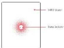
| WiFi Indicator(Blue) | Steady On Connected with Router | |
| One flash per second | Settaining for a network or disconnected from Router | |
| Off | 1) initialization (the Control Panel beeps every 2 seconds; less for up to 30 seconds after power up2) The Power Adapter is not plugged in | |
| Status Indicator(Rest, Blue and Green) | Steady On Stable Will connection | |
| Red System's Armec | ||
| Blue System is in Home Mode(Past Arm) | ||
| Green System's Disarmed | ||
| One flash per second | Divorrigated from the RoLer | |
| Three flashes per second | Alarm condition | |
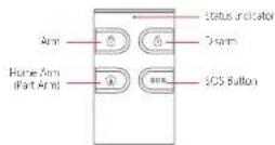
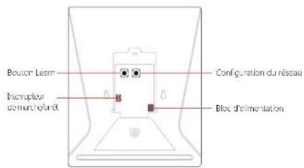
Functionality of Buttons behind the Back Cover
| Loam Used to | pair an accessory with the Control Panel |
| Wifi Used to | pair the Control Panel with the Router |
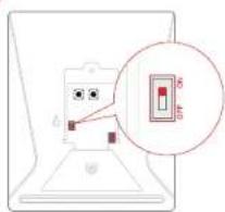
| On/off Power switch | |
Note: The Control Panel must be clugged in to the Power Adapter in order to maintain the Will connection.
When AC power is lost, the control panel will last for 2 minutes to send out a push notification to the connected smartphones, and the sounder will keep keeping for 30 seconds.
EN
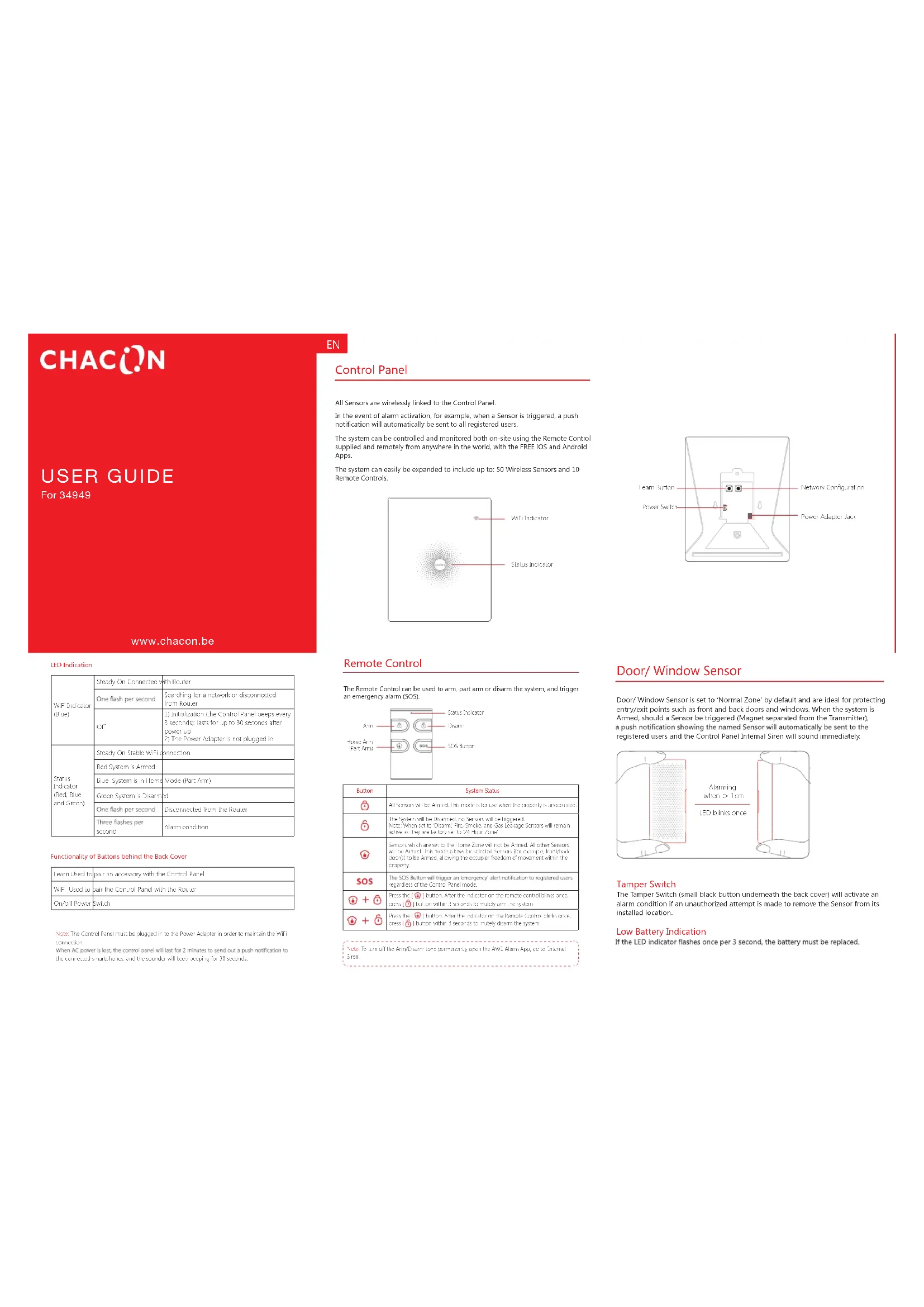
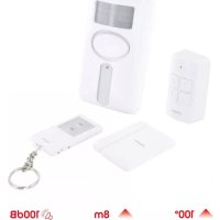
Control Panel
All Sensors are wirelessly linked to the Control Panel.
In the event of alarm activation, for example, when a Sensor is triggered, a push notification will automatically be sent to all registered users.
The system can be controlled and monitored both on-site using the Remote Control supplied and remotely from anywhere in the world, with the FREE iOS and Android Apps.
The system can easily be expanded to include up to: 50 Wireless Sensors and 10 Remote Controls.
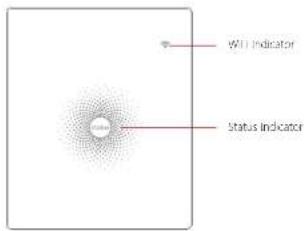
Remote Control
The Remote Control can be used to arm, part arm or disarm the system, and trigger an emergency alarm (SOS).
| Button | System Status |
| All Sensors will be Annex. This mode is a flow when the property is unoccupied. | |
| The System will be Disarmed, no Sensors will be triaged. Note: When set to Annex, Fire, Sadder, and Bars Exchange Sensors will remain alive with they are so busy let us 211 you zone? | |
| Sensors which are set to the Home Zone will be Anned. All other Sensors will be Anned. This notice allows for serviceed Sensors for example, hand/track door(s) to Be Anned, allowing the occupier freedom of movement within the property. | |
| SOS | The SOS Button will trigger an emergency alert notification to registered users required class of the Control Panel module. |
| Please call 1 Button. A's the Inicio on the Services Control Blindfulness press. 2 Button was 3 seconds to must say the system. | |
| Inside 1 Button. After the indicator on the Entrance Control Blindion or press. 3 Button was 4 seconds to must say that this system. |
Note: To turn of the Amr/Disarm are permanently open the AHI Amr Apa go to Internal SecY
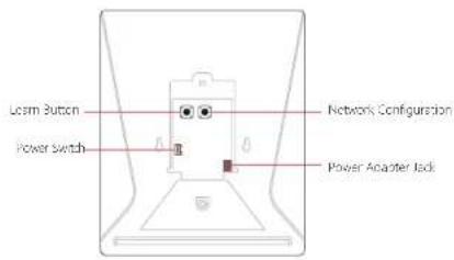
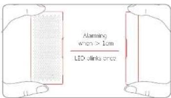
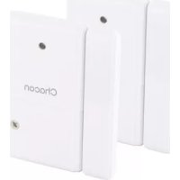
Door/ Window Sensor
Door/ Window Sensor is set to 'Normal Zone' by default and are ideal for protecting entry/exit points such as front and back doors and windows. When the system is Armed, should a Sensor be triggered (Magnet separated from the Transmitter), a push notification showing the named Sensor will automatically be sent to the registered users and the Control Panel Internal Siren will sound immediately.
Tamper Switch
The Tamper Switch (small black button underneath the back cover) will activate an alarm condition if an unauthorized attempt is made to remove the Sensor from its installed location.
Low Battery Indication
If the LED indicator flashes once per 3 second, the battery must be replaced.
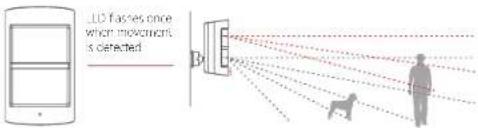
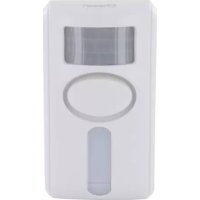
Pet Immune PIR Motion Sensor
The Motion Sensor is designed for use on interior walls and is set to Home Mode by default. Whenever the Sensor detects movement (while the alarm is armed) you will receive a push alert notification showing the name of the Sensor that has been triggered and the Control Panel Internal Siren will sound immediately.
Tamper Switch
The Tamper Switch (a black button with a silver spring at the top, located inside this Sensor) is used to indicate an unauthorized attempt to remove its cover. Whenever this button is released, it will trigger an alarm and the push alert will notify you which Sensor has been triggered on tamper.
Low Battery Indication
If the LED indicator blinks once per 3 second, the battery must be replaced.
WiFi Setup
Step One: Download the App
The App can be downloaded from the App Store or Google Play by searching for "AW1 Alarm".
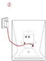
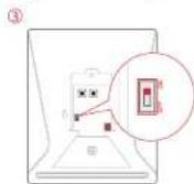
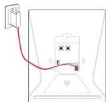
Step Two: Power On
- Remove the back cover from the Control Panel.
- Connect the Power Adapter.
- Set the Power Switch to "ON".
- Wait until the WiFi Indicator starts to blink (approx. 30 seconds)
Note: The Conro Panel will emit a short beep every 3 seconds when powered up. After 50 seconds there will be a long beep to confirm that the Panel is ready for use.
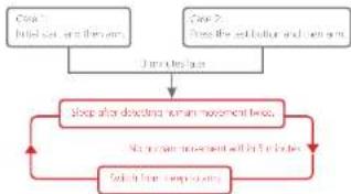
Working Mode
Test Mode
The Sensor enters a 1 minute settling down period on power up, thereafter entering into Test Mode. In Test Mode, the Sensor detects movement every 10 seconds and emits an alarm signal every time movement is detected. Test Mode will remain active for 3 minutes, thereafter entering into Power Saving Mode.
Note: You may also enter Test Mode by pressing the Test Button at the back of the Sensor.
Power Saving Mode
If the Sensor detects movement twice within 3 minutes the Sensor will automatically enter into Sleep Mode and no movement will be detected. The Sensor will leave Sleep Mode after a 3 minute period without any movement.
flowchart
graph TD
    A["Input: Input can be the area"] --> B{Processing}
    B --> C["Output: Output can be the area"]
    C --> D["Feedback Loop"]
    D --> E["Output: Output can be the area"]
    E --> F["Output: Output can be the area"]
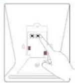
Pairing New Accessories to the Control Panel
There are two ways of pairing Accessories to the Control Panel – manually and via App.
Manual Pairing
To pair Accessories manually please follow the instructions below:
Remote Control and Sensors
-
Press the Learn button at the back of the Control Panel
-
Press any button on the Remote Control or trigger the Sensor
Very Important: Please note that pressing the Tamper Switch instead of triggering the Sensor will register it as a 24 Hour Zone.
(Optional Accessory) Wireless Siren
-
Press the Learn Button on the Siren
-
Arm the Control Panel via the App
Pairing from the App
To pair the Accessories via App, open the AWL Alarm App, go to 'Edit Accessories' and follow the instructions on the screen.
Step Three: Connect the Control Panel to the Router
Important: AW1 does not support WiFi of 5GHz band, if dual-band(5GHz and 2.4GHz) router is used, make sure to connect with the 2.4GHz WiFi instead of the 5GHz's. Make sure your smartphone is connected to the local WiFi network and then follow the steps in the App to connect the AW1 Control Panel to the Router.
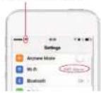
1. Press and hold the [W·F] Button inside the Control Panel for 3 seconds, the Control Panel will emit one 'beep'.
2. Tap [WiFi] in the [Settings] of your smartphone, and select the 'WiFi Alarm' network.
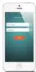
3. Return to the App and key in your WiFi name and password or open the drop down menu to scan for all the nearby wireless networks.
4. The Control Panel will beep once, wait until the WiFi indicator and the Status indicator stop blinking, indicating that the Control Panel has successfully connected to the network.
①
②
Make sure this network iron appears in the Status Bio
③
④
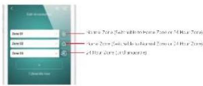
Normal Zone ■ Sensors set to Normal Zone are armed whether the alarm is in Arm (Full Arm) or Home Arm (Part Arm) Mode. We recommend setting Window/Door Sensors to Normal Zone.
Home Zone 1: Sensors set to Home Zone are only armed in Arm (Full Arm) Mode. If Home Mode (Part Arm) is used, these Sensors are not armed and will not activate the alarm on trigger. We recommend setting PIR Motion Sensors to Home Zone, 24 Hour Zone 7 Sensors set to 24 Hour zone will activate the alarm when triggered, regardless of the alarm status at the time farmed or disarmed.
Hain Smoke. Box Linkage or Water Road Sensors are automatically registered as 24 Hour Zone Sensors and cannot be changed to Normal or Home Zone. Any Motion or Door Window Sensor paired to the Control Panel by pressing the Torper Station will also register as a 24 Hour Zone Sensor. A 24 Hour Sensor will activate the alarm when Uganda, regardless of the alarm status at the time (amalor or charmed):
Internal Siren
The volume level, alarm duration, and arm/disarm beep can be adjusted in the App.
Wireless Siren
When connecting an Outdoor Siren (optional accessory) to the Control Panel, it can be enabled/ disabled by switching the Alarm option to on/off. The on/off arm/disarm beep and alarm duration can also be adjusted.
Exit Delay Time
Set a time delay for you to leave your property without triggering an alarm.
APP Control and Settings
Important Notice
In order to control the system remotely (WiFi/App), the Control Panel must be 'mains' powered via the Power Adapter. WiFi accessibility is disabled when the Control Panel Power Adapter is unplugged from the mains power supply and running on batteries.
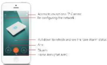
Entry Delay Time
Set a time delay for you to enter your property without triggering an alarm.
Timed Arm/Disarm
The system can be programmed to automatically Arm and Disarm the alarm at predefined times by following the steps below:
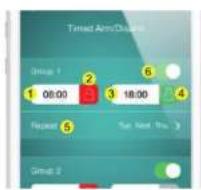
- Set the time you want the alarm to arm (on the left)
- Tap the Arm Button once to activate automatic arming and twice to disable it
- Set the time you want the alarm to Disarm (on the right)
- Tap the Disarm Button once to activate automatic disarming and twice to disable
the automatic disarming - Select the days you want the alarm to automatically arm/ disarm
- Slide the switch to the 'on' position to activate the new schedule
Synchronize Time (Important Setting)
The time shown on your mobile device must be synchronized with the time shown on the Server prior to setup. Operation history will only be recorded once synchronization is complete.
Edit Accessories
Rename, add, delete and change the Zone Mode of each Sensor (except the 24 Hour Zone). Remember to tap the Save button in the top right hand corner to save the changes.
Ringtone of Push Alert
The selected ringtone will be heard when a Push Alert is received.
History
The Event Log holds a record of up to 100 events (More details in 'Notifications' on page 13).
Passcode
We recommend that passcode protection is enabled to avoid unauthorized access to the App.
Delete User
The alarm can be controlled by up to 5 Users who will also receive Push Alerts. To delete a User Account from the App go to the submenu 'More' and select 'Delete Users'.
Notifications
The system uses status notification to give you feedback about how the system is functioning.
Operation Notification (Record in App Menu-History)
| System Arm System armed by Remote Control | |
| System Disarm System dissarmed by Remote Control | |
| System Home Arm System home armed by Remote Control | |
| Arm by App System armed by App. | |
| Disarm by App System dissarmed by App. | |
| Home Arm by App System home armed by App | |
| Arm as Scheduled | System has auto-armed according to the 'Timed Army/Disarm' schedule. |
| Disarm as Scheduled | System has auto-disarmed according to the 'Timed Army/Disarm' schedule |
Alarm Notification
| System SOS Alarm | Remove Control SOS button activation has triggered an emergency alert |
| (Zone I) Alarm A zone | no.1 sensor has been triggered |
| (Zone I) Tamaer Alarm | Unauthorized attempt to remove the cover of a zone no.1 sensor. |
Door/ Window Sensor.
Step 1: To power up the Sensor, remove the Battery Tab
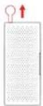
Step 2: Attach the Adhesive Pads to the back of the Transmitter and Magnet
Status Notification
| Zone 1) Low Battery | A zone no. 1 sensor battery is low. Change the battery as soon as possible. |
| Control panel AC failure lost connection with AC Power | |
| Control panel AC recovery Regain connection with AC Power | |
Installation
Control Panel
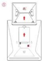
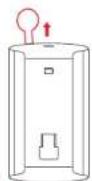
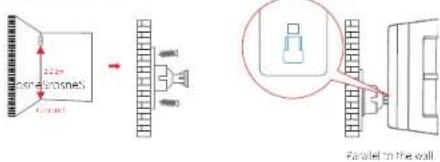
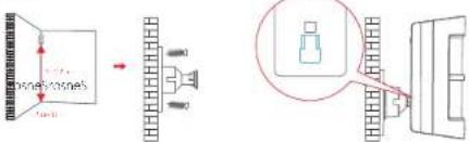
Wall Mounting
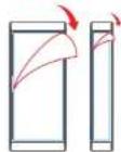
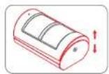
The Control Panel can be wall mounted using the Wall Bracket provided.
Using the screws supply, mount the Wall Bracket onto the wall ensuring that the arrow on the bracket is pointing upwardly, then match-up the Wall Bracket hooks to the holes at the back of the Control Panel, and slide the Control Panel down onto the Wall Bracket.
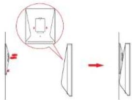
Step 3: Place the Sensor on the door/ window frame and the magnet on the door/ window ensuring that the distance between them is not greater than 1cm when the door/ window is shut.
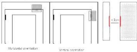
PIR Motion Sensor.
Warning Do not install
Free-standing
The Wall Bracket can also be used as a tabletop stand.
Turn the Wall Bracket upside down so that the arrow is pointing downwards, and align the screw hole underneath the Control Panel Battery Cover with the screw hole on the Wall Bracket. Use the remaining screw to secure in place.
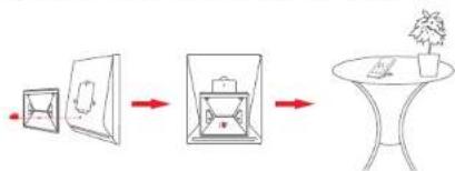
flowchart
graph LR
    A["Box with lid"] --> B["Folded Box"]
    B --> C["Table with potted plant"]
Warning:
A weak WiFi signal can seriously affect the performance of this Security Alarm System. Please make sure that the Control Panel is located as close as possible to the main Router for optimal connectivity.
Direction of motion and Detection Range
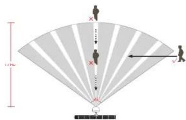
It is easier to detect objects that move sideways in front of the sensor, but more difficult to detect objects that move directly toward the sensor.
Step 1 To power up the Sensor, remove the Battery Tau
Step 2 Perform a Walk Test Sensor
Press the Test Mode button at the back of the sensor to put it in Test Mode.
Place the Sensor in your desired location (don't use screws at this point), arm the system and walk in front of the Sensor to test that the Sensor triggers the alarm.
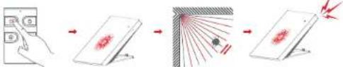
Step 3: Install the sensor
Replacing Accessory Batteries
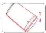
Remote Control

Remove the screw Open the casing
Door/Window Sensor
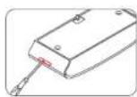
Open the casing
PIR Motion Sensor
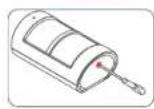
Remove the screw Open the casing
FAQ
Failed to connect to the Wi-Fi
Check whether the WiFi Indicator on the Control Panel has stopped flashing
If the WiFi Indicator stops flashing and the Control Panel cannot be controlled from the App, please make sure that your local WiFi network is available and working properly.
Check that the WiFi name and password are correct.
Connect to a 2.4G WiFi network instead of 5G
Check that the Power Adapter is connected to the Control Panel.
Re-linking the Control Panel to the Router again by following the steps on page 7
The WiFi indicator and the status indicator are on, but I can't control the alarm by App
Check that your smartphone is connected to a WiFi network.
Wait a few minutes to see if the WiFi indicator and the status indicator start flashing. If they do, your local WiFi network is not stable. Make sure that the Control Panel is located in an area with good WiFi coverage and then re-pair with your local WiFi network.
No response from the Control Panel when a Sensor is triggered
The Sensor is not within range of the Control Panel.
Check that the Sensor has been successfully paired to the Control Panel: Press any Button on the Remote Control, am the system and separate the Contact from the Magnetic Sensor or press the Test Button on the Motion Sensor. You can re-pair the Sensor to the Control Panel by following the instructions in the App - [Edit Accessories] - [Show Me How]
I can't Arm or Home Arm (Part Arm) my alarm by App
If the alarm has been triggered and hasn't been disarmed and a user tries to Arm or Home Arm the System, an error notification will appear stating "Operation failed". In event of Operation Failure first disarm the system and then try again.
How to delete an Accessory
You can delete any Sensor in the App by going to [Edit Accessories] and tapping the 'bin' icon in the top right hand corner of the screen.
To delete all accessories press and hold the [Learn] button inside the Control Panel for 3 seconds, the Control Panel will beep once to indicate that all accessories have been deleted.
No sound when alarming
Check that the Control Panel Alarm volume is not set to mute and the ring time is not set to '0'.
Adjust the volume and the ring time accordingly.
How to reset the alarm system
Press and hold the [WiFi] button inside the Control Panel for 7 seconds.
You will hear one short beep after 3 seconds and then a long beep after another 4 seconds.
The reset has been completed and all the settings have been restored to default conditions.
Please note that this process does not delete any Sensors.
I've done the reset but I keep receiving notifications from the Control Panel
To stop receiving notifications from the Control Panel you can either do a Reset or Delete User (submenu 'More') within the App, but make sure the panel has been connected with WiFi network before the operation.
Specifications
Control Panel
Power Supply DC 12V 500 mA
Battery 3/V 60D mAn L-Ion x1pc
Battery Life Recharge Cycle 300 times
Will ILL 202.11b/g/
Standby Current <27mA
Alarm Current <180 mA
Interval Siren 85 dB
Optional Accessories 10 Remote Controls, 30 Sensors
Radio Frequency 315 MHz or 73.92 MHz
Housing Material A&S Plastic
Operating Condition
Relative Humidity <80% (non-concerns)
Control Pane Dimensions 125 x 150 x 30 mm (L x W x H)
Bracket Dimensions 87.5 x 81.5 x 12 mm (L x W x H)
Remote Control
Power Supply DC 3V (CR2025 lithium battery x 1pc)
Transmit Current <7 mA
Transmitting Distance <60 m (open area/no interference)
Radio Frequency 3.5 MHz or 433.92 MHz
Losing Materia ADS Plastic
Operating Condition
Temperature 0°C\~+55°C
Relative Humidity <80% [non-condensing]
Dimension: 53 x 3' x 11 mm (xW x H)
Door/ Window Sensor
Power Supply DC 3V (CR2C32 lithium battery x 2pcs)
Static Cancer, <5 μA
Alarm Current <9 mA
Transmitting Distance <90 m (open area/no interference)
Radio Frequency 315 MHz or 433.92 MHz
Housing Materials ABS Plastic
Operating Conditions Temperature D°C\~+55°C
Relative Humidity <80% [non-condensing]
Transmitter Dimensions 71 x 31.5 x 15 mm (L x W x H)
Magnet Dimensions 71 × 12.5 × 15 mm (L × W × H)
Power Supply DC 3V (AA 1.5V LRS battery x 2pcs)
Static Current <25 μA
Alarm Current <13 mA
Detection Scope 8m/110°
Transmitting Distance <80 m (open arc/arc interference)
Radio Frequency 315 MHz or 433.92 MHz
Housing Material ABS Plastic
Operation Crysteine Temperature 0°C-+55°C
Ke above Humidity - Coats (not corning),
Selector Denscore 20.5 × 59 × 43 mm × 8 × W × 10
3-racket Dimensions 52 x 30 x 26.5 mm (L x W x H)
Voyants LED
flowchart
graph LR
    A["Small Box"] --> B["Large Box"]
    B --> C["Small Box on Table"]
    C --> D["Potted Plant"]
Attention
natural_image
Two technical diagrams showing a folded paper or sheet with a ruler and a red-circled component, no text or symbols present.FAQ
Batterie 1 oil rechargeable Li-ion 3.7V 500 mAh
Led-Indicatoren
Staande opstelling
Deur /raamsensor:
Radiofrequency 315 MHz of 433.92 MHz
Material behuizing Kunststoff (A35)
| Temporaat 0 °C, Jc. 155 °C | |
| Bedrijfsondities | Relieve vochtlighole < 80% (zonder cordens) |
| Afmeingen bodieningsparecel | 125 x 150 x 30 mm (1 x 0 x h) |
| Afmeingen montageelaar | 87,5 x 81,5 x 12 mm (1 x 0 x h) |
Afstandsbediening
| Vocding | 3 V DC (2 CR2025 libvmbullerij) |
| Signas stroomverbruik | < 7 mA |
| Zondtobruik | < 80 m (open ruimie / gcom interferonici) |
| Radiofrequente | 315 MHz of 433,92 MHz |
| Molecular bohuieling | Kunstof (ABS) |
| Temperatuur u °C tor +55 °C | |
| Bedrij scondities | Rogdavic vochtigheid < 80% (zonder condens) |
| Mehingen | 53 x 41 x 11 mm (x o x h) |
Deur /raamsensor
| Vocding | 3 V DC (2 CR2032 bilu-ssbeidrijur) |
| Stroomverbruik in rust | < 5 μA |
| Alumroomverbruik | < 9 mA |
| Zandtobruk | < 80 m (open ruimie / geen interferenle) |
| Radiofrequente | 325 MHz of 433,92 MHz |
| Material Bohuizing | Konzulof (ABS) |
| Temperatuur 0 °C to: +55 °C | |
| Bedrijfcondities | Re-eleve vochtighele < 80% (zonder condens) |
| Afmetingen zender | 71 x 31,5 x 15 mm (x o x h) |
| Afmetingen magreet | 71 x 12,5 x 15 mm (x o x h) |
flowchart
graph LR
    A["Box with red arrow"] --> B["Folded Box"]
    B --> C["Table with potted plant"]
Advertencia.
Paso 3: Instale el detector
②
natural_image
Simple line drawing of a device with a red cable connecting its top and bottom ports (no text or symbols)③
④

flowchart
graph LR
    A["Small Box"] --> B["Add Box"]
    B --> C["Add Box on Table"]
    C --> D["Potted Plant"]
Aviso:
natural_image
Two technical line drawings of a mechanical component, one showing a cutaway view and the other a detailed cross-section with red arrows indicating motion (no text or symbols)FCC Compliance Statement: This device complies with Part 15 of the FCC roles. Operation is subjected to the following two conditions: (1) this device may cause harmful interference, and (2) its device must accept any interference received, including interference that may cause undesired operation.
CHACON declares that the 34945, 34946, 34947, 34952, 34953, 34955, 34957, 34958, 34950, 34950 device is compiled with the essential requirements and other relevant provisions of Directive 1999/CCC
EN301489-1V1.9.2:2011
EN501489371 EN524762019
EN300220-1V2.4.1:2012
EN 60950:1:2006+A11:X009+A1:2010+A12:2011+A21:2013
EN60950-1:2006 Am17:2009;Am1:2010;Am12:2011;Am2:2013

if the alarm system no longer functions or can no longer be repaired, it must be disposed of according to the valid statutory regulations. Disposal of spent batteries/accumulators:
You are required by the (bottery) (Batteries) to return all spent inductors and accumulators. Disposing of spent soundless components with common household waste is prohibited. Batteries/accumulators near contain hazardous substances are envolved with the symbols on the side. These symbols indicate that it is prohibited to dispose of these batteries/accumulators to the household waste. The correspondents for the respective heavy metals ore: Catecothium, Figmercury, Porelak. You can return spent biotubes and accumulators that can no longer be changed to the designated collection palets in your community, outlets or websites batteries or accumulators are set. Following these instructions will allow you to fulfil the legal requirements and contribute to the pure tea of our environment!


- EN
- Control Panel
- Remote Control
- Door/ Window Sensor
- Tamper Switch
- Low Battery Indication
- Pet Immune PIR Motion Sensor
- WiFi Setup
- Step One: Download the App
- Step Two: Power On
- Working Mode
- Power Saving Mode
- Pairing New Accessories to the Control Panel
- Manual Pairing
- Step Three: Connect the Control Panel to the Router
- Internal Siren
- Wireless Siren
- Exit Delay Time
- APP Control and Settings
- Important Notice
- Entry Delay Time
- Timed Arm/Disarm
- Synchronize Time (Important Setting)
- Edit Accessories
- Ringtone of Push Alert
- History
- Passcode
- Delete User
- Notifications
- Door/ Window Sensor.
- Installation
- PIR Motion Sensor.
- Free-standing
- Warning:
- Replacing Accessory Batteries
- FAQ
- Specifications
- Attention
- Staande opstelling
- Deur /raamsensor:
- Aviso:
Brand : CHACON
Model : 34949
Category : Alarm system