
CUE28NKR - Air-conditioner PANASONIC - Free user manual and instructions
Find the device manual for free CUE28NKR PANASONIC in PDF.
| Product type | Wall split air conditioner |
| Brand | Panasonic |
| Model | CUE28NKR |
| Category | Air conditioner |
| Cooling capacity | 28000 BTU/h (estimated) |
| Heating capacity | 28000 BTU/h (estimated) |
| Power supply | 230 V, 50 Hz |
| Refrigerant | R32 |
| Compressor | Inverter |
| Sound level | 48 dB(A) (estimated) |
| Indoor unit dimensions | 1050 x 335 x 265 mm (estimated) |
| Indoor unit weight | 12 kg (estimated) |
| Outdoor unit dimensions | 850 x 620 x 310 mm (estimated) |
| Outdoor unit weight | 40 kg (estimated) |
| Main functions | Cooling, heating, dehumidification, ventilation |
| Connectivity | Compatible with IntesisHome Wi-Fi module (optional) |
| Sensor | External temperature sensor for MKE and NKE models |
| Safety | Overheat protection, automatic defrost |
| Maintenance and cleaning | Regular filter cleaning, connection check |
| Spare parts and repairability | Parts available, repair by certified technician |
| General information | 2-year warranty, professional installation recommended |
Frequently Asked Questions - CUE28NKR PANASONIC
User questions about CUE28NKR PANASONIC
0 question about this device. Answer the ones you know or ask your own.
Ask a new question about this device
Download the instructions for your Air-conditioner in PDF format for free! Find your manual CUE28NKR - PANASONIC and take your electronic device back in hand. On this page are published all the documents necessary for the use of your device. CUE28NKR by PANASONIC.
USER MANUAL CUE28NKR PANASONIC
Your Home In The Cloud

PA-AC-WIFI-1A
INSTALLATION GUIDE
Installation process should only be performed by an authorized installer. Please follow all Safety Instructions provided by the Panasonic manuals.
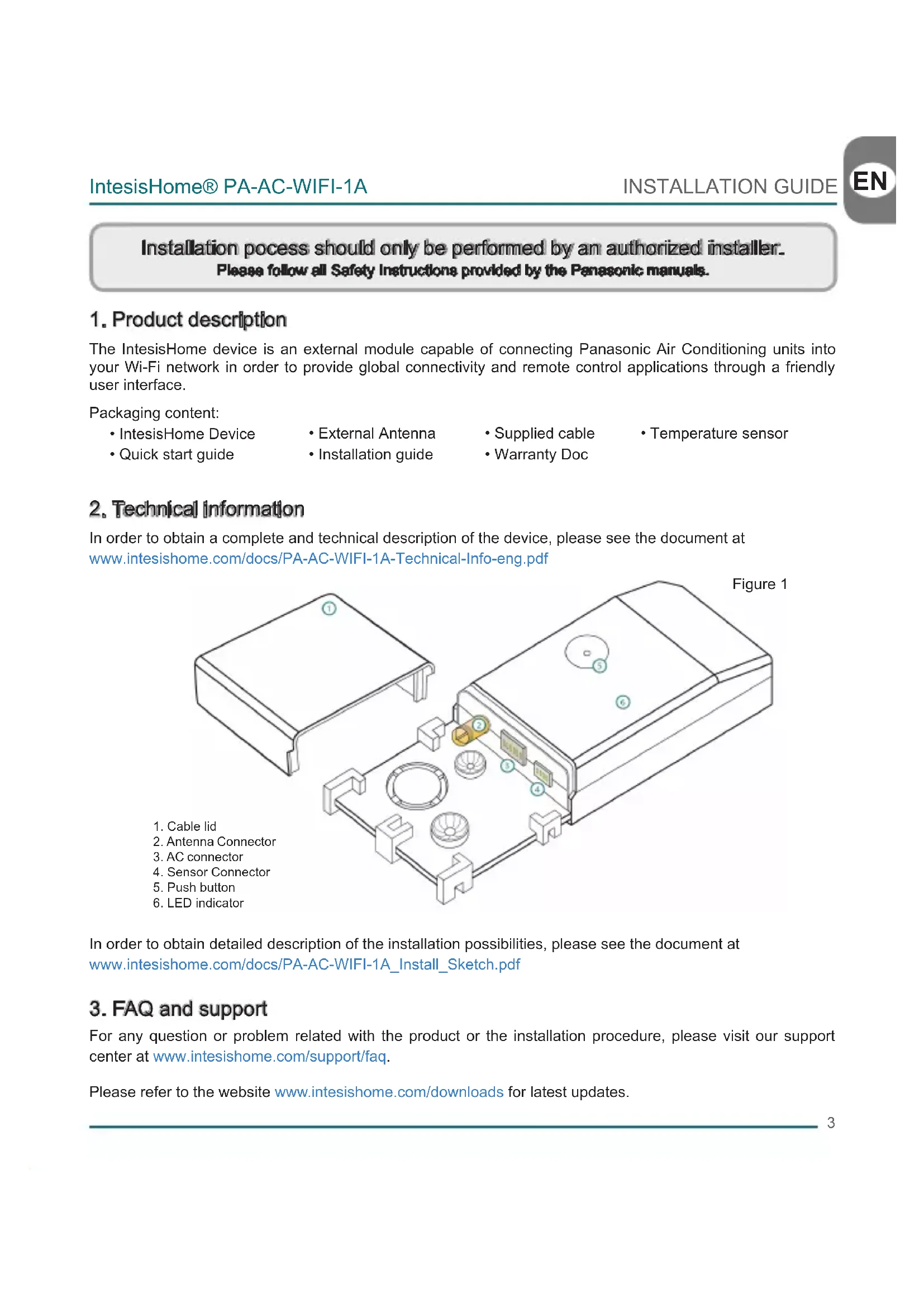
1.Product description
The IntesisHome device is an external module capable of connecting Panasonic Air Conditioning units into your Wi-Fi network in order to provide global connectivity and remote control applications through a friendly user interface.
Packaging content:
IntesisHome Device
-
External Antenna
-
Supplied cable
-
Temperature sensor
-
Quick start guide
Installation guide
Warranty Doc
2. Technical Information
In order to obtain a complete and technical description of the device, please see the document at www.intesishome.com/docs/PA-AC-WIFI-1A-Technical-Info-eng.pdf
In order to obtain detailed description of the installation possibilities, please see the document at www.intesishome.com/docs/PA-AC-WIFI-1A_Install_Sketch.pdf
3. FAQ and support
For any question or problem related with the product or the installation procedure, please visit our support center at www.intesishome.com/support/faq.
Please refer to the website www.intesishome.com/downloads for latest updates.
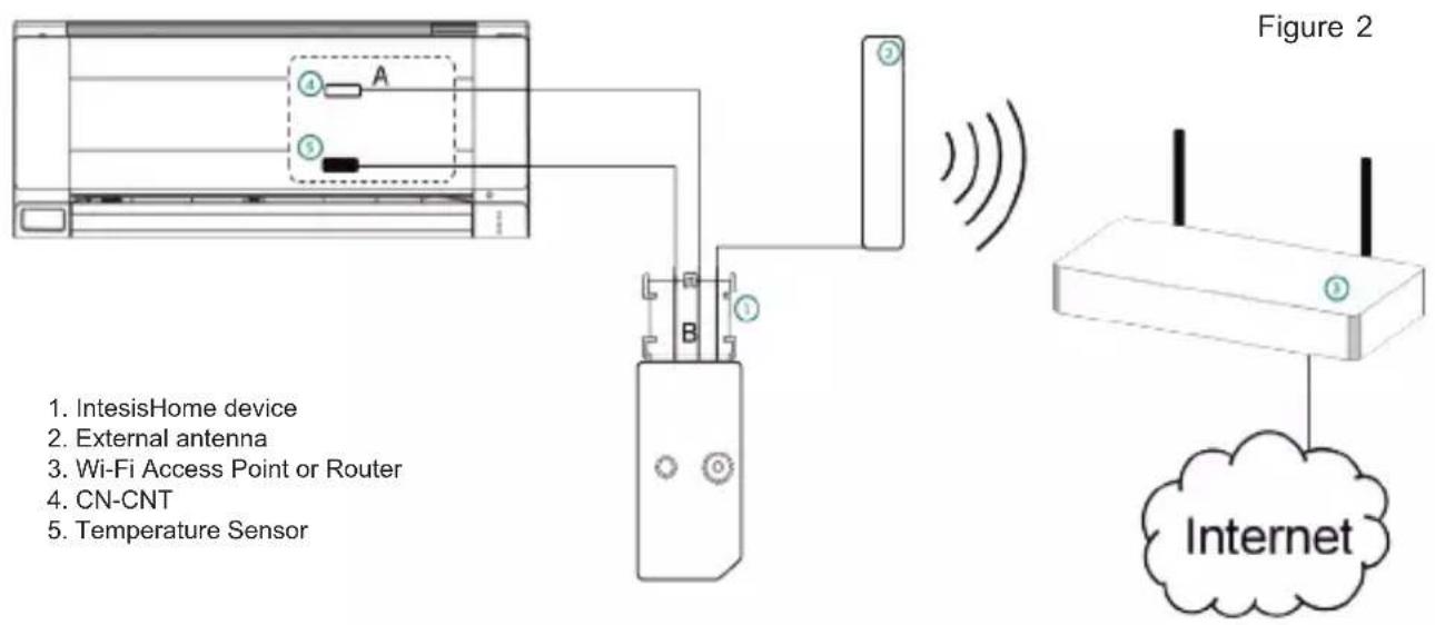
4. Installation overview
5. Device connections
- Unplug the Air conditioner (AC) unit from the power supply line.
- Access to the main Printed Circuit Board.*
- Locate the socket connector marked as CN-CNT*
- Select a location for the IntesisHome device. See section 6 for more information.
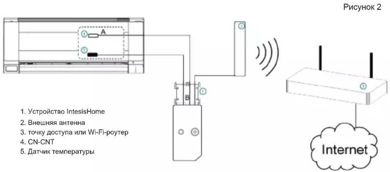
- Connect the A-end (the long one) of the supplied cable to the Air Conditioner CN-CNT connector and the B-end (the short one) to the device AC connector.
- Connect the external antenna into the antenna connector. Make sure you screw the antenna connector in a clockwise direction until it stops.
- (If needed) Install the Temperature Sensor. See section 8 for more information.
- Place the antenna outside the AC, preferably in a vertical position and pointing directly to the Wi-Fi Router or Access Point (AP). See section 7 for more information.
- Close the Air Conditioner unit.
- Plug the AC to the power supply line. If connection with the Air Conditioner has been successful, IntesisHome device LED will start blinking Green and then will change to steady Green.
- See Panasonic installation or service manual for detailed information.
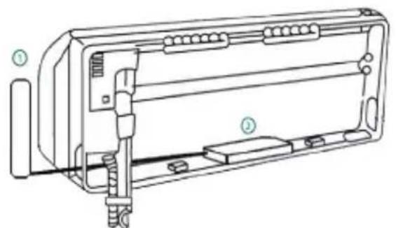
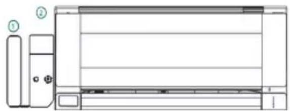
6. Device location
IntesisHome device can be both installed inside or outside the AC units.
In order to obtain detailed description of the installation possibilities, please see the document at www.intesishome.com/docs/PA-AC-WIFI-1A_Install_Sketch.pdf
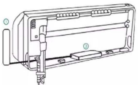
Inside the AC unit Outside the AC unit
1. External antenna
2. IntesisHome device
Device Installed Inside the AC unit or hidden
It allows a neater installation as the user cannot see the device during normal operation. The following points need to be taken into account if the device is installed inside the AC.
- The indication LED and the button are not going to be accessible by the user.
o The LED is an indicator of the status of the device both during connection and normal behavior.
o The button is used to reconfigure the device if the Access Point (AP) configuration changes. If this happens the user will need to access the inside of the Air Conditioner.
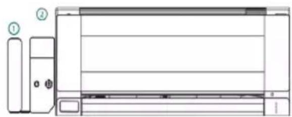
- If there is not enough space for installation inside the AC unit the following actions can be performed:
o If it is due to water pipes, change the side of the AC where they are connected to get more space inside the AC unit.
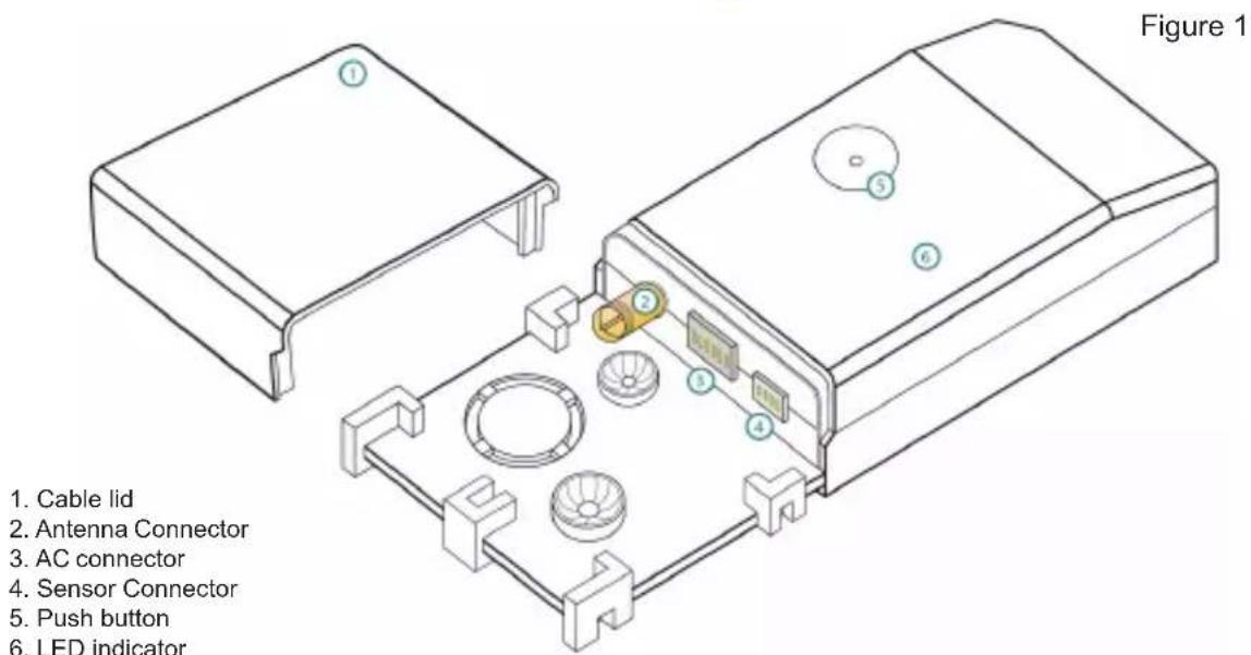
o Otherwise the support surface can be removed (Figure 1)
Device Installed outside the AC unit
The following points need to be taken into account if the device is installed outside the AC.
- The device can be fixed both using screws of double side tape.
- The cable lid has several options in order to direct the cables to the desired direction.
7. Antenna location
Locating the external antenna in a proper location and position will improve communication between the IntessHome device and your Wi-Fi Router or Access Point (AP).
Remember to correctly screw the antenna connector in a clockwise direction until it stops.
Important: Avoid placing the antenna next to metal surfaces.
Important: When possible, try to check Wi-Fi coverage in the installation location. Good Wi-Fi level is strongly recommended.
Fix the external antenna preferably as close as possible from the Wi-Fi signal source (Access Point or Router). Please, make sure that you place the antenna in a vertical position and pointing directly to your Wi-Fi Router or Access Point (AP).
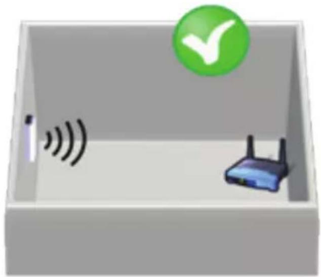
Figure 4
Antenna in vertical position and pointing to the Wi-Fi Access Point or Router.
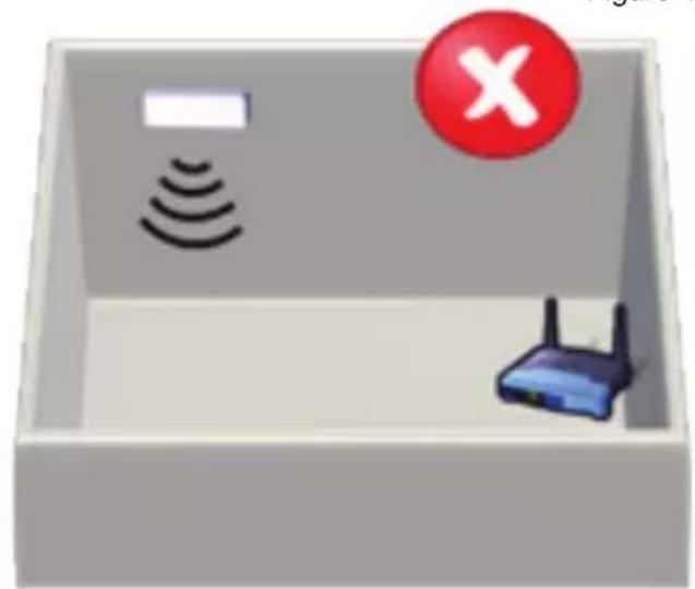
Antenna im Inertionfall position and net pointing to the Wi-Fi Access Point or Router.
If you have coverage problems after installation, please visit the connectivity support section in our site at www.intesishome.com/support/faq
8. Temperature Sensor location
The supplied temperature sensor only needs to be installed in MKE and NKE units. Newer models do not require an external temperature sensor.
Connect the temperature sensor to the device Temperature Sensor connector (Figure 1) and fix the other end next to the Air Conditioner intake air sensor.
See www.intesishome.com/docs/PA-AC-WIFI-1A_Install_Sketch.pdf for more information
Se www.intesishome.com/docs/PA-AC-WIFI-1A_Install_Sketch.pdf for mer information
IhOpMaunO nocJeDnX oBHOeHmX MoKHO haTn Ha caTe www.intesishome.com/downloads.

4.Obuee onncaHne yctaHOBKn
5.Подкючени устpoиства
-
OToeHNHTe KOHdNcNoHep OT cTe NITaHnA.
-
OtkpoTe KpbIuKy DoCTyNa K rJaBHO neaTHo nIaTe.*
-
HainTe pa3bem c uΦpom CN-CNT.*
-
BbI6epnte MeTo dny yCTaHOBKn ycTpoiCtBa IntesisHome. Iopno6Hee cm. pa3dien 6.
-
IopKIOHTe KOHeA (dHnHHb) KOMIIeKTHOrO Ka6eIa pa3bemy KOHNuHOhepa, 06o3HaueHHomy CN-CNT, a KOHeB (kopOTkn) K pa3bemy AC yctpoiCTBa.
-
BCTaBbTe Ka6eNb BHeUHei aHTeHHbI B pa3bEm IJn aHTeHHbI. CoeHHTeNb aHTeHHoro Ka6eNa Heo6xOIMo BKpyTntB rHe3do no YacOBOn CtpenKe Do ynopa.
-
Pn Heo6xOIMOCIn yCTaHOBtE DaTcIK Tempeatpybl. NpOp6Hee cm. pa3dcl 8.
-
BbIbeIte aHTeHHy 3a Kopnyc KOHNiCNoHepa JxelaTeBHo B BepTnKaIbHOM nIOXeHnn HnPaBbTe npraMo Ha Wi-Fi poyter nn ToOCTyna (AP). POnp6Hee cm. pa3dJ 7.
-
3akpoIte 6nok KOHduuOhepa.
-
NOKIIOHTe KOHNIOHep K cETn nITaHna.Ecnn coeINHeHne C KOHNIOHepom yCTaHOJIeHO, 3eNEbI CBToNDnOcNTembl IntesisHome cnpBa HauHET MIRATb, a 3aTeM 6yDet ropeTb He MIRaJ.
* Pioopoe Hee cm. PykoOIOCTBO no yctaHOBKe nIIN o6cnyxuBaHnIO Panasonic.
6. Pa3MeueHne yctpoiCTBa
YcTpoNCTBO IntesisHome MoXHo ycTaHaBnBaTb KaK BHyTpN KOHdIuNoHepa, TaK BHe erO.
Bollee noDpo6Hoe onncahne BO3MOxHocTe yCTaHOBKn MOxHo haHTN B cIeNyUoem DOkymeHTe: www.intesishome.com/docs/PA-AC-WIFI-1A_Install_Sketch.pdf
PncyHOK3
BHyTpNi KOHdIuNoHepa CkpIta yCTaHObKa
1.BheHra aHTeHHa
2. YctpoIcTBo IntesisHome
YcTaHOBKa BHyTpN KOHNHOHePa Hn CkpbTaN YcTaHOBKa
Takoi BnD yCTaHOBKn aKKypaThee, XOTB O6bHbIX ycNOBnx 3KcNpyaTuIN yCTpOInCTBO cKpbITo OT rna3 NOB3OBaTeNa. B Cnyae yCTaHOBKn yCTpOInCTBa BHyTpN KOHNIOHePA Heo6xOIMO yueCTb CneNyUOnne OC6EHHOCTN.
- CBeToIIOHbI INHnKATOp I KHOJaB 3TOM cnyae 6ydyHT HeIOCTyINbIMN dIg NOJIb3OBaTeJIa
O INHnKaTOp nOKa3bIbAeT COCToRHe yCTpOcTBA KaK npN NOkJIIOUeHnn, TaK N B HopMaJIbHOM peKmpepa60Tbl.
o o Khonka nCnoJb3yetc dIJI nepeinporpaMMnpOBaHnY yCTpoiCTBa npI CMeHe TOnKn DoCTyna (AP). B 3TOM cIyuae noIb3ObaTeB bIHykDeH 6yDet OTKpbItb DOCTyn K BHyTpHeHn Yactn KOHduuHOhep.
- Ecnn BnTyprn KOHdNtioHepa HeoctaToUHO MeCTa IyCTaHOBKn YcTPOIcTBa, Heo6xOIMo BbINONHTb CneNyIOuee:
o Ecn MeCTa He XBatae Tno npuHHe BOJHBIX Tpy6OK, NOcOeHNHTe IX K KOHdUHOpey C npOTUBONIOJXHO CTOpOHbl.
O IINJXe MoXHO CHaTb ONOpHyIO NobepxHocTb (Pnc.1).
YcTaHOBka BHe KOHNuNHOpea
B cnyuae yctahOBKn ycTpoiCTBa BHe KOHdunnohepa Heo6xoDnmo yueCt b CneDuOune Oc06eHHocn.
- YcTpoIcTB MoXHO 3aKpeNITb KaK Ha BnHTax, TaK Na DByCTOpOHem CKOTHe.
KoHCTpykui KaBbHOrO OTeKa Daet BO3MOXHOCTb yKnaDbBaTb Ka6eIN B HxHOM HnpaBHeHH. 45

7. NOnOKeHHe aHTeHHbI
YcTaHOBJIeHHa B HAdnEkaUem MeCte N HAnpaBJIeHHN BHeHJra aHTehHa yLyUaet CBa3b MExdy yCTpoiCTBOM IntesisHome n Wi-Fi-poyTePOM nIu ToKo DocTyna (T).
POMHHTe, UTO COeINHITeJIb aHTeHHoro Ka6eIa Heo6xoJIMo BkpyTnB rHe3do no yacOBon CTpeJIke do ynopa
Baxno: Hcyctayraaeeaae aHTENHY 8nssmetauHxckox noepxhocten.
Baa: NonbtaTecb npaepnbp nappnne csnWAFFi maate yctanoe, 6013 80mooHO. Mbl HactcrtbnHpokomHpyem mmbxxpounyypocnhcnnna Wi-Fi.
BHeuHIO aHTeHHy Heo6xOIMO yCTaHaBnBaTb MaKcMaJIbHO 6IIN3KO K NCTOCHky CnIHana Wi-Fi (TOUKe DoCTyna IIN MapwpyTu3aTOpY). IOnKaIyIcTa, npOBepbTe, YTo6bl aHTeHHa HaxOINacb B BePTNkAlbHOM INoJoxHmN i 6bl Na HapabNeHa nprMo Ha Wi-Fi-poyTepr IIN ToUkY DoCTyna (TД).
PncyHOK4

AHTeHHH HxDyMTCA BepTnHgBnONrTOcONHm HnnpaBHeHa HToKy ApOCTyDaAMn Wt-FI-poynp

AHTeHHa HxOyTcB TropasHTanbHOM monnssnnm He HanpaaneHa Ha ToKy doCTyna nn W-Fl-poyrep
Ecnn nocne yctaHOBN y BAC BO3HKn npo6IeMb C NOKpbITHe, 3aJnte B pa3JeN NOdepKKn CoeHHeN caTa www.intesishome.com/support/faq
8. MecTo yCTaHOBKn DaTUnKa TempePaTypbI
KOMnJIeKTHbI DaTcHk TempeaTypbI Tpe6yET OTeJbHo yCTaHOBKn ToIbKO B MoJeIax MKE n NKE. B 6oJIee HObIX MoeJIAX BHeUHNI TempeaTypbI DaTcHk He Tpe6yETcra.
IodcoeHnHTe DaTnK Tempeatpyb K pa3bemy TempeatypHoro daTnka yctpoiCTBa (Pnc.1), a BtopoN KoHeC Ka6eJra - K daTnky npntOuHoro BO3dyxa KOHNIOHepa.
CMOTPNTeDONOHHTeBHyO pdf.
HOpMaunu
www.intesishome.com/docs/PA-AC-WIFI-1A_Install_Sketch.