
WM14DBL - Screwdriver HiKOKI - Free user manual and instructions
Find the device manual for free WM14DBL HiKOKI in PDF.

| Product type | Cordless electronic impact screwdriver |
| Brand | HiKOKI |
| Model | WM14DBL |
| Tightening capacity (bolt mode) | Standard bolt M4 – M10 |
| Max tightening torque | 30 N·m (bolt mode, tightening time 3 s) |
| No-load speed (electronic impulse mode) | 0 – 1100 min⁻¹ |
| Impact rate (electronic impulse mode) | 0 – 1090 min⁻¹ |
| Operating modes | Electronic impulse, bolt, self-drilling screw, drilling, electronic clutch (5 positions) |
| Power source | Lithium‑ion battery 14.4 V, 3.0 Ah (BSL1430) |
| Included charger | UC18YRSL (14.4 V – 18 V) |
| Charging time (at 20 °C) | Approx. 45 minutes |
| Dimensions (L × H × W) with battery | 162 mm × 250 mm × 31 mm |
| Weight with battery | 1.5 kg |
| Housing material | Reinforced plastic |
| Residual charge indicator | Red LED indicator (3 levels) activated by button |
| Integrated light | White LED, switchable, auto-off after 15 min |
| Belt hook | Yes, removable, screw attachment |
| Included accessories | Charger UC18YRSL, 2 batteries BSL1430, plastic case, battery cover |
| Maintenance | Clean with a soft, dry cloth; no solvents |
| Storage | Temperature below 40 °C, out of reach of children |
| Built‑in protections | Thermal protection (automatic shutdown), overload protection |
| Sound level (acoustic pressure) | LpA = 74 dB(A), LWA = 85 dB(A), uncertainty K = 3 dB(A) |
| Vibration level (impact tightening) | ah = 11.5 m/s², K = 1.5 m/s² |
| Warranty | Complies with national regulations; covers manufacturing defects, not normal wear |
Frequently Asked Questions - WM14DBL HiKOKI
User questions about WM14DBL HiKOKI
0 question about this device. Answer the ones you know or ask your own.
Ask a new question about this device
Download the instructions for your Screwdriver in PDF format for free! Find your manual WM14DBL - HiKOKI and take your electronic device back in hand. On this page are published all the documents necessary for the use of your device. WM14DBL by HiKOKI.
USER MANUAL WM14DBL HiKOKI
Read all safety warnings and all instructions.
Failure to follow the warnings and instructions may result in electric shock, fire and/or serious injury.
Save all warnings and instructions for future reference.
The term "power tool" in the warnings refers to your mains-operated (corded) power tool or battery-operated (cordless) power tool.
1) Work area safety
a) Keep work area clean and well lit.
Cluttered or dark areas invite accidents.
b) Do not operate power tools in explosive atmospheres, such as in the presence of flammable liquids, gases or dust.
Power tools create sparks which may ignite the dust or fumes.
c) Keep children and bystanders away while operating a power tool.
Distractions can cause you to lose control.
2) Electrical safety
a) Power tool plugs must match the outlet.
Never modify the plug in any way.
Do not use any adapter plugs with earthed (grounded) power tools.
Unmodified plugs and matching outlets will reduce risk of electric shock.
b) Avoid body contact with earthed or grounded surfaces, such as pipes, radiators, ranges and refrigerators.
There is an increased risk of electric shock if your body is earthed or grounded.
c) Do not expose power tools to rain or wet conditions.
Water entering a power tool will increase the risk of electric shock.
d) Do not abuse the cord. Never use the cord for carrying, pulling or unplugging the power tool. Keep cord away from heat, oil, sharp edges or moving parts.
Damaged or entangled cords increase the risk of electric shock.
e) When operating a power tool outdoors, use an extension cord suitable for outdoor use.
Use of a cord suitable for outdoor use reduces the risk of electric shock.
f) If operating a power tool in a damp location is unavoidable, use a residual current device (RCD) protected supply.
Use of an RCD reduces the risk of electric shock.
3) Personal safety
a) Stay alert, watch what you are doing and use common sense when operating a power tool. Do not use a power tool while you are tired or under the influence of drugs, alcohol or medication.
A moment of inattention while operating power tools may result in serious personal injury.
b) Use personal protective equipment. Always wear eye protection.
Protective equipment such as dust mask, nonskid safety shoes, hard hat, or hearing protection used for appropriate conditions will reduce personal injuries.
c) Prevent unintentional starting. Ensure the switch is in the off-position before connecting to power source and/or battery pack, picking up or carrying the tool.
Carrying power tools with your finger on the switch or energising power tools that have the switch on invites accidents.
d) Remove any adjusting key or wrench before turning the power tool on.
A wrench or a key left attached to a rotating part of the power tool may result in personal injury.
e) Do not overreach. Keep proper footing and balance at all times.
This enables better control of the power tool in unexpected situations.
f) Dress properly. Do not wear loose clothing or jewellery. Keep your hair, clothing and gloves away from moving parts.
Loose clothes, jewellery or long hair can be caught in moving parts.
g) If devices are provided for the connection of dust extraction and collection facilities, ensure these are connected and properly used.
Use of dust collection can reduce dust related hazards.
4) Power tool use and care
a) Do not force the power tool. Use the correct power tool for your application.
The correct power tool will do the job better and safer at the rate for which it was designed.
b) Do not use the power tool if the switch does not turn it on and off.
Any power tool that cannot be controlled with the switch is dangerous and must be repaired.
c) Disconnect the plug from the power source and/or the battery pack from the power tool before making any adjustments, changing accessories, or storing power tools.
Such preventive safety measures reduce the risk of starting the power tool accidentally.
d) Store idle power tools out of the reach of children and do not allow persons unfamiliar with the power tool or these instructions to operate the power tool.
Power tools are dangerous in the hands of untrained users.
e) Maintain power tools. Check for misalignment or binding of moving parts, breakage of parts and any other condition that may affect the power tools operation.
If damaged, have the power tool repaired before use.
Many accidents are caused by poorly maintained power tools.
f) Keep cutting tools sharp and clean.
Properly maintained cutting tools with sharp cutting edges are less likely to bind and are easier to control.
g) Use the power tool, accessories and tool bits etc. in accordance with these instructions, taking into account the working conditions and the work to be performed.
Use of the power tool for operations different from those intended could result in a hazardous situation.
5) Battery tool use and care
a) Recharge only with the charger specified by the manufacturer.
A charger that is suitable for one type of battery pack may create a risk of fire when used with another battery pack.
b) Use power tools only with specifically designated battery packs.
Use of any other battery packs may create a risk of injury and fire.
c) When battery pack is not in use, keep it away from other metal objects like paper clips, coins, keys, nails, screws, or other small metal objects that can make a connection from one terminal to another.
Shorting the battery terminals together may cause burns or a fire.
d) Under abusive conditions, liquid may be ejected from the battery; avoid contact. If contact accidentally occurs, flush with water. If liquid contacts eyes, additionally seek medical help. Liquid ejected from the battery may cause irritation or burns.
6) Service
a) Have your power tool serviced by a qualified repair person using only identical replacement parts.
This will ensure that the safety of the power tool is maintained.
PRECAUTION
Keep children and infirm persons away.
When not in use, tools should be stored out of reach of children and infirm persons.
PRECAUTIONS FOR ELECTRONIC PULSE DRIVER
- This is a portable tool for drilling, tightening and loosening screws. Use it only for these operations.
- Use the earplugs if using for a long time.
- One-hand operation is extremely dangerous; hold the unit firmly with both hands when operating.
- After installing the driver bit, pull lightly out the bit to make sure that it does not come loose. If the bit is not installed properly, it can come loose during use, which can be dangerous.
- Use the bit that matches the screw.
- Tightening a screw with the tool at an angle to that screw can damage the head of the screw and the proper force will not be transmitted to the screw. Tighten with this tool lined up straight with the screw.
- Always charge the battery at a temperature of 0 - 40°C A temperature of less than 0°C will result in over charging which is dangerous. The battery cannot be charged at a temperature greater than 40°C The most suitable temperature for charging is that of 20 - 25°C
- Do not use the charger continuously. When one charging is completed, leave the charger for about 15 minutes before the next charging of battery.
- Do not allow foreign matter to enter the hole for connecting the rechargeable battery.
- Never disassemble the rechargeable battery and charger.
- Never short-circuit the rechargeable battery. Short-circuiting the battery will cause a great electric current and overheat. It results in burn or damage to the battery.
- Do not dispose of the battery in fire. If the battery burnt, it may explode.
- Do not insert object into the air ventilation slots of the charger.
Inserting metal objects or inflammables into the charger air ventilation slots will result in electrical shock hazard or damaged charger.
- Bring the battery to the shop from which it was purchased as soon as the post-charging battery life becomes too short for practical use. Do not dispose of the exhausted battery.
- Using an exhausted battery will damage the charger.
- When drilling in wall, floor or ceiling, check for buried electric power cord, etc.
CAUTION ON LITHIUM-ION BATTERY
To extend the lifetime, the lithium-ion battery equips with the protection function to stop the output.
In the cases of 1 to 3 described below, when using this product, even if you are pulling the switch, the motor may stop. This is not the trouble but the result of protection function.
- When the battery power remaining runs out, the motor stops. In such a case, charge it up immediately.
- If the tool is overloaded, the motor may stop. In this case, release the switch of tool and eliminate causes of overloading. After that, you can use it again.
- If the battery is overheated under overload work, the battery power may stop. In this case, stop using the battery and let the battery cool. After that, you can use it again.
Furthermore, please heed the following warning and caution.
WARNING
In order to prevent any battery leakage, heat generation, smoke emission, explosion and ignition beforehand, please be sure to heed the following precautions.
- Make sure that swarf and dust do not collect on the battery.
ODuring work make sure that swarf and dust do not fall on the battery.
Make sure that any swarf and dust falling on the power tool during work do not collect on the battery.
Do not store an unused battery in a location exposed to swarf and dust.
Before storing a battery, remove any swarf and dust that may adhere to it and do not store it together with metal parts (screws, nails, etc.). - Do not pierce battery with a sharp object such as a nail, strike with a hammer, step on, throw or subject the battery to severe physical shock.
- Do not use an apparently damaged or deformed battery.
- Do not use the battery in reverse polarity.
- Do not connect directly to an electrical outlets or car cigarette lighter sockets.
- Do not use the battery for a purpose other than those specified.
- If the battery charging fails to complete even when a specified recharging time has elapsed, immediately stop further recharging.
- Do not put or subject the battery to high temperatures or high pressure such as into a microwave oven, dryer, or high pressure container.
- Keep away from fire immediately when leakage or foul odor are detected.
- Do not use in a location where strong static electricity generates.
- If there is battery leakage, foul odor, heat generated, discolored or deformed, or in any way appears abnormal during use, recharging or storage, immediately remove it from the equipment or battery charger, and stop use.
CAUTION
- If liquid leaking from the battery gets into your eyes, do not rub your eyes and wash them well with fresh clean water such as tap water and contact a doctor immediately.
If left untreated, the liquid may cause eye-problems.
- If liquid leaks onto your skin or clothes, wash well with clean water such as tap water immediately. There is a possibility that this can cause skin irritation.
- If you find rust, foul odor, overheating, discolor, deformation, and/or other irregularities when using the battery for the first time, do not use and return it to your supplier or vendor.
WARNING
If an electrically conductive foreign object enters the terminals of the lithium ion battery, a short-circuit may occur resulting in the risk of fire. Please observe the following matters when storing the battery.
Do not place electrically conductive cuttings, nails, steel wire, copper wire or other wire in the storage case.
Either install the battery in the power tool or store by securely pressing into the battery cover until the ventilation holes are concealed to prevent short-circuits (See Fig. 1).
SPECIFICATIONS
POWER TOOL
| Model WM14DBL WM18DBL | ||||
| Capacity | Electronic pulse mode | Wood screw | ø 4.2 × 75 | |
| Bolt mode | Ordinary bolt M4 - M10 | |||
| High tension bolt | M4 - M6 | |||
| Self drilling screw mode | Self drilling screw | ø 6 | ||
| Drill mode Steel | Woodwork drilling | ø 21 | ||
| drilling ø 10 | ||||
| Mortar drilling | ø 6 | |||
| Electronic clutchmode | Small screw M6 | |||
| Tightening torque [when fully charged at 20°C temp] | Bolt mode Tightening time: 3 sec.] Tightening strength grade 12.9) Hexagon socket used | Maximum 30 N·m Maximum 33 N·m {306 kgf·cm} {337 kgf·cm} | ||
| ing is M10 high tension bolt | ||||
| Drill mode | 11 N·m {112 kgf·cm} | |||
| Electronic clutch mode | 5-point clutch 2.3 - 5.3 N·m {23 - 54 kgf·cm} | |||
| Edge shape | Width across flat 6.35, bit insertion shape | |||
| Motor | DC motor | |||
| No-load speed [when fully charged at 20°C temp] | Electronic pulse mode 0 - 1 | 100 min-1 | ||
| Bolt mode | 0 - 640 min-1 | |||
| Self drilling screw mode | 0 - 1100 min-1 | |||
| Drill mode | 0 - 1100 min-1 | |||
| Electronic clutch mode | 0 - 450 min-1 | |||
| Number of blows [when fully charged at 20°C temp] | Electronic pulse mode 0 - 1 | 090 min-1 | ||
| Bolt mode | 0 - 1090 min-1 | |||
| Self drilling screw mode | 0 - 1090 min-1 | |||
| Rechargeable battery | BSL1430: Li-ion 14.4 V (3.0 Ah, 8 cells) | BSL1830: Li-ion 18 V (3.0 Ah, 10 cells) | ||
| Dimensions of the tool Entire length × height × center height | 162 mm × 250 mm × 31 mm (BSL1430 attached) | 162 mm × 252 mm × 31 mm (BSL1830 attached) | ||
| Weight | 1.5 kg (BSL1430 attached) | 1.7 kg (BSL1830 attached) | ||
| LED light | White LED | |||
| Remaining battery indicator lamp | Red LED | |||
CHARGER
| Model | UC18YRL |
| Charging voltage | 14.4 V 18 V |
| Weight 0.6 kg |
STANDARD ACCESSORIES
In addition to the main unit (1), the package contains the accessories listed in the table below.
| WM14DBL (2LSRK) | ① Charger (UC18YRSL) 1 ② Battery (BSL1430) 2 ③ Plastic case 1 ④ Battery cover 1 |
| WM14DBL (NN) | Without charger, battery, plastic case and battery cover. |
| WM18DBL (2LSRK) | ① Charger (UC18YRSL) 1 ② Battery (BSL1830) 2 ③ Plastic case 1 ④ Battery cover 1 |
| WM18DBL (NN) | Without charger, battery, plastic case and battery cover. |
Standard accessories are subject to change without notice.
OPTIONAL ACCESSORIES (Sold separately)
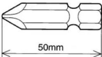
- Plus driver bit
| Bit No. Code No. | |
| No. 2 992671 | |
| No. 3 992672 |
- Hexagonal socket
| Part Name | Engraved characters | L | B | Code No. |
| 5 mm Hexagonal socket 8 | 65 8 996177 | |||
| 6 mm Hexagonal socket 10 | 65 10 985329 | |||
| 5/16" Hexagonal socket | 12 65 12 | 9961 | 78 | |
| 8 mm Hexagonal socket 13 | 65 13 996179 | |||
| 10 mm Hexagonal socket (small type) | 14 65 14 | 996180 | ||
| 10 mm Hexagonal socket | 16 65 16 | 996181 | ||
| 10 mm Hexagonal socket | 17 65 17 | 996182 | ||
| 1/2" Hexagonal long socket | 21 | 166 | 21 | 996197 |
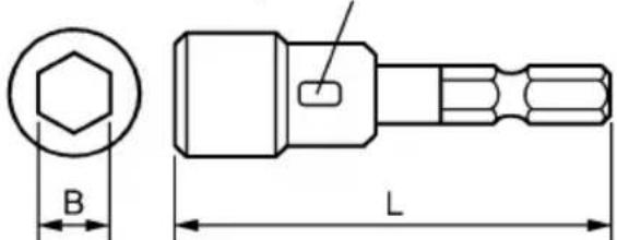
Engraved characters
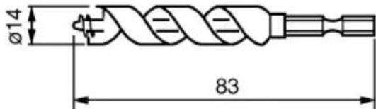
- Wood working drill: Code No. 959183
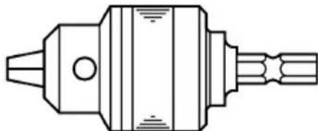
- Drill chuck adapter set: Code No. 321823
Use drill bits available on the local market.
Optional accessories are subject to change without notice.
APPLICATION
Driving and removing of small screws, small bolts, machine screws, wood screws, tapping screws, etc.
Drilling of various woods.
Drilling of various metals.
BATTERY REMOVAL/INSTALLATION
- Battery removal
Hold the handle tightly and push the battery latch to remove the battery (see Figs. 1 and 2).
CAUTION:
Never short-circuit the battery.
- Battery installation
Insert the battery while observing its polarities (see Fig. 2).
CHARGING
Before using the Electronic pulse driver, charge the battery as follows.
- Connect the charger's power cord to a receptacle.
When the power cord is connected, the charger's pilot lamp will blink in red. (At 1-second intervals)
- Insert the battery into the charger.
Firmly insert the battery into the charger until the lines are visible, as shown in Figs. 3 and 4.
- Charging
When inserting a battery in the charger, charging will commence and the pilot lamp will light continuously in red.
When the battery becomes fully recharged, the pilot lamp will blink in red. (At 1-second intervals) (See Table 1)
(1) Pilot lamp indication
The indications of the pilot lamp will be as shown in Table 1, according to the condition of the charger or the rechargeable battery.
Table 1
| Indications of the pilot lamp | ||||
| The pilot lamp lights or blinks in red. | Before charging | Blinks | Lights for 0.5 seconds. Does not light for 0.5 seconds. (off for 0.5 seconds) | |
| While charging | Lights | Lights continuously | ||
| Charging complete | Blinks | Lights for 0.5 seconds. Does not light for 0.5 seconds. (off for 0.5 seconds) | ||
| Charging impossible | Flickers | Lights for 0.1 seconds. Does not light for 0.1 seconds. (off for 0.1 seconds) | Malfunction in the battery or the charger | |
| The pilot lamp lights in green. | Overheat standby | Lights | Lights continuously | Battery overheated. Unable to charge (Charging will commence when battery cools). |
(2) Regarding the temperatures of the rechargeable battery
The temperatures for rechargeable batteries are as shown in Table 2, and batteries that have become hot should be cooled for a while before being recharged.
Table 2 Recharging ranges of batteries
| Rechargeable batteries | Temperatures at which the battery can be recharged |
| BSL1430, BSL1830 | 0°C – 50°C |
(3) Regarding recharging time
Depending on the combination of the charger and batteries, the charging time will become as shown in Table 3.
Table 3 Charging time (At 20 ° C )
| Charger Battery | UC18YRSL |
| BSL1430, BSL1830 | Approx. 45 min. |
NOTE:
The charging time may vary according to temperature and power source voltage.
-
Disconnect the charger's power cord from the receptacle.
-
Hold the charger firmly and pull out the battery.
NOTE:
After operation, pull out batteries from the charger first, and then keep the batteries properly.
How to make the batteries perform longer
(1) Recharge the batteries before they become completely exhausted.
When you feel that the power of the tool becomes weaker, stop using the tool and recharge its battery. If you continue to use the tool and exhaust the electric current, the battery may be damaged and its life will become shorter.
(2) Avoid recharging at high temperatures.
A rechargeable battery will be hot immediately after use. If such a battery is recharged immediately after use, its internal chemical substance will deteriorate, and the battery life will be shortened. Leave the battery and recharge it after it has cooled for a while.
CAUTION:
When the battery charger has been continuously used, the battery charger is heated, thus constituting the cause of failures. Once the charging has been completed, give 15 minutes rest until the next charging.
If the battery is recharged when it is warm due to battery use or exposure to sunlight, the pilot lamp may light in green.
The battery will not be recharged. In such a case, let the battery cool before charging.
When the pilot lamp flickers in red (at 0.2-second intervals), check for and take out any foreign objects in the charger's battery installation hole. If there are no foreign objects, it is probable that the battery or charger is malfunctioning. Take it to your authorized Service Center.
PRIOR TO OPERATION
- Preparing and checking the work environment
Make sure that the work site meets all the conditions laid forth in the precautions.
- Checking the battery
Make sure that the battery is installed firmly. If it is at all loose it could come off and cause an accident.
- Installing the bit
Driver bit
Always follow the following procedure to install driver bit. (Fig. 5)
(1) Pull the guide sleeve back.
(2) Insert the bit into the hexagonal hole in the anvil.
(3) Release the guide sleeve and it returns to its original position.
CAUTION:
If the guide sleeve does not return to its original position, then the bit is not installed properly.
Drill bit
- A drill with hexagonal shank can be attached directly to the tool.
- To attach a drill without hexagonal shank, you need to have the drill chuck adapter set sold separately.
(1) Insert the drill bit into the chuck.
(2) Use the chuck key to secure the drill bit, tightening the chuck by each of the three holes in turn. (Fig. 11)
- Use an iron drill to make a pilot hole for a wood screw or a 10mm or smaller hole.
(1) Insert the drill bit into the chuck.
(2) Use the chuck key to secure the drill bit, tightening the chuck by each of the three holes in turn. (Fig. 11)
HOW TO USE
1. Mode selection function
WARNING
Use this tool with the mode selection dial set to the correct position (it should be clicked and locked in place).
Ignoring this may cause an unexpected behavior of the tool and result in breaking materials/screws or injury.
CAUTION:
Do not apply strong impact to the mode selection dial.
The operation mode can be changed by turning the mode selection dial on the tool and aligning it with the triangular mark.
The operation mode can be selected from five different modes described in the below table.
NOTE:
The tightening torque obtained by each mode varies according to the screw and material being screwed. Adjust the mode selection dial after test-tightening a few screws.
Use the bolt mode to tighten bolts.
Turning the mode selection dial with the tool switched on does not change the mode. Switch off the tool before changing the operation mode.
Example of mode selection
| Operation mode | Marking | Maximum torque | Application Notes | |||
| Electronic pulse mode | T | 3 | —— Tightening | Wood screw tightening screw shorter | Diagonal tightening of 75 mm screw | ○Use the bit and socket which are suitable for the screw diameter. ○When using the drill mode, be sure not to stop the motor rotation. |
| 2 | Tightening of 50 - 75 mm screw | |||||
| 1 | than 50 mm | |||||
| Bolt mode | T | 30 N·m 33 N·m | *1 Bolt tightening | |||
| Self drilling screw mode | T | 2 Self drilling | g screw tightening (ø5 orø6) | |||
| 1 Self drilling | g screw tightening (ø3.5 orø4)*2 | |||||
| Drill mode 11 N | m Drilling | |||||
| Electronic clutch mode *4 | T | 5 5.3 N·m | *3 screw (M6) or tapping screw tightening, board fixing | |||
| 4 | ||||||
| 3 Machine screw | ||||||
| 2 Gypsum | ||||||
| 1 2.3 N·m | ||||||
1: WM14DBL: 30 N·m, WM18DBL: 33 N·m.
2: Before fixing a thin plate with a self drilling screw, make sure that the thickness of the plate is suitable for the screw diameter.
3: With the electronic clutch mode 4 or 5, the tool may execute reverse rotation briefly when the load increases in order to reduce a risk of screw-head damage.
4: The tool starts up in low rotation speed and tightens softly.
The motor automatically stops rotating when the torque reaches to the number set on the dial in order to reduce over tightening.
The clutch sound such as of the mechanical type will not be generated.
2. Characteristics of Electronic Pulse Driver
Unlike a conventional impact driver, the electronic pulse driver generates the striking force by rotating the motor in regular and reverse directions repeatedly. This mechanism has helped to provide quieter operation.
The following characteristics are uncommon to a conventional impact driver, however these are not signs of malfunction.
The tool tends to be heated by continuous screw tightening.
To protect the motor and electronic parts that control the motor operation, this tool is equipped with a temperature protection circuit.
Depending on the screw and material being screwed, the striking operation may start early.
Since the striking operation causes temperature increase of the motor and electronic parts, the temperature protection circuit may be activated early. Refer to "1. Continuous operation" on page 13 for recovering from the operation stop caused by the temperature protection circuit.
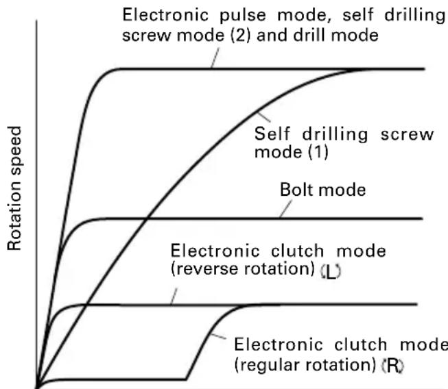
Also, the electronic pulse driver controls the motor rotation consistently to provide the optimum operation for each mode.
Because of this, the following cases can occur during operation.
The behavior at operation start differs by the mode.
The self drilling screw mode (1) gradually increases the speed.
The electronic clutch mode (regular rotation) rotates the motor at a very slow speed for a certain period after the start and then increases the speed.
On the other hand, the electronic clutch mode (reverse rotation) meets the preset rotation speed immediately after the start.
Elapsed time after switching on
The tool may not return to the initial status from the striking operation.
When the bit or socket is removed from the screw or bolt while the switch is being pulled, the tool may continue the striking operation.
To return to the initial status, turn off the switch and then start the next operation.
Motor rotation speed does not decrease even when the remaining battery power becomes low.
Since this tool adopts the constant-speed control, the rotation speed is almost unchanged even when the remaining amount of the battery becomes low. This allows users to operate the tool efficiently until the battery runs down. However, it is difficult to know the remaining battery power from the rotation speed and the tool may stop suddenly during work.
Check the remaining battery power by pressing the remaining battery indicator switch at times.
The tool stops automatically when the electronic clutch is actuated.
Quiet screw tightening can be performed without clutch sound generated by the mechanical type.
The tool stops automatically when the clutch is actuated. If you continue to use the tool, turn off the switch once and turn it on again. When the tool does not operate even without load, the remaining amount of the battery is low. In this case, recharge the battery immediately.
3. Check the rotational direction
The bit rotates clockwise (viewed from the rear side) by pushing the R-side of the push button.
The L-side of the push button is pushed to turn the bit counterclockwise. (See Fig. 6) (The (L) and marks are provided on the body.)
CAUTION:
The push button can not be switched while the tool is turning. To switch the push button, stop the tool, then set the push button.
4. Switch operation
- When the trigger switch is depressed, the tool rotates.
- When the trigger is released, the tool stops.
The rotational speed can be controlled by varying the amount that the trigger switch is pulled. Speed is low when the trigger switch is pulled slightly and increases as the trigger switch is pulled more.
5. Using the hook
The hook is used to hang up the power tool to your waist belt while working.
CAUTION:
When using the hook, hang up the power tool firmly not to drop accidentally.
If the power tool is dropped, it may lead to an accident.
When carrying the power tool hooked to your waist belt, do not fit any bit to the tip of power tool. If the sharp bit such as drill is fitted to the power tool when carrying it hooked to your waist belt, you will be injured.
Install securely the hook. Unless the hook is securely installed, it may cause an injury while being used.
(1) Removing the hook.
Remove the screws fixing the hook with Philips screw driver. (Fig. 7)
(2) Replacing the hook and tightening the screws. Install securely the hook in the groove of power tool and tighten the screws to fix the hook firmly. (Fig. 8)
6. About Remaining Battery Indicator
When pressing the remaining battery indicator switch, the remaining battery indicator lamp lights and the battery remaining power can be checked. (Fig. 9) When releasing your finger from the remaining battery indicator switch, the remaining battery indicator lamp goes off. The Table 4 shows the state of remaining battery indicator lamp and the battery remaining power.
Table 4
| State of lamp | Battery Remaining Power |
| The battery remaining power is enough. | |
| The battery remaining power is a half. | |
| The battery remaining power is nearly empty. Re-charge the battery soonest possible. |
As the remaining battery indicator shows somewhat differently depending on ambient temperature and battery characteristics, read it as a reference.
NOTE:
Do not give a strong shock to the switch panel or break it. It may lead to a trouble.
To save the battery power consumption, the remaining battery indicator lamp lights while pressing the remaining battery indicator switch.
7. How to use the LED light
Every time you press the light switch on the switch panel, the LED light lights or goes off. (Fig. 10) To prevent the battery power consumption, turn off the LED light frequently.
CAUTION:
Do not expose directly your eyes to the light by looking into the light.
If your eyes are continuously exposed to the light, your eyes will be hurt.
NOTE:
To prevent the battery power consumption caused by forgetting to turn off the LED light, the light goes off automatically in about 15 minutes.
8. Tightening and loosening screws
Install the bit that matches the screw, line up the bit in the grooves of the head of the screw, then tighten it. Push the tool just enough to keep the bit fitting the head of the screw.
CAUTION:
Applying the tool for too long tightens the screw too much and can break it.
Tightening a screw with the tool at an angle to that screw can damage the head of the screw and the proper force will not be transmitted to the screw.
Tighten with this tool lined up straight with the screw.
Use the bit that fits the cross recess on the screw head. Make sure to use an appropriate bit especially when tightening self drilling screws since using an inappropriate bit can topple the screws.
9. Work amount possible with one charging
The following table shows the approximate amount of work to be carried out by the tool with one charging. (The number of screws tightened and that of boring operations differ slightly according to the hardness of wood or metal, the ambient temperature, the charger properties, etc.)
| Operation mode Operation | Model | WM14DBL W | WM18DBL | |
| Electronic pulse mode | Wood screw tighteningø 4.2 × 75 | Lauan Approx. 240 | Approx. 290 | |
| Bolt mode Bolt tightening M10 × 30 | S10C Approx. | 750 Approx. | 900 | |
| Self drilling screw mode | Self drilling screw tighteningø 5 × 19 | C-channel t2.3 + SPCC t1.6 | Approx. 160 | Approx. 190 |
| Drill mode | Woodwork drillingø 15 | American pine t18 | Approx. 450 | Approx. 540 |
| Steel drillingø 6.5 | SPCC t1.6 | Approx. 120 | Approx. 145 | |
| Mortar drillingø 6 × 30 | Mortar | Approx. 80 | Approx. 95 | |
| Electronic clutch mode | Machine screw tightening M6 × 12 | S10C | Approx. 1000 | Approx. 1200 |
OPERATIONAL CAUTIONS
1. Continuous operation
When you perform the striking operation continuously, the temperature protection circuit may be activated early. (Refer to "2. Characteristics of Electronic Pulse Driver" on page 11.)
When the activated temperature protection circuit stops the tool, the LED light flashes to indicate that the tool is heated to high temperature. The LED light goes off automatically after approx. 30 seconds.
When you perform continuous operation, allow the tool to rest for around 15 minutes at a replacement of rechargeable battery.
NOTE:
When the tool is stopped by the activated temperature protection circuit, allow the tool to cool sufficiently. You can use the tool again when it cools down.
While the tool is not cooled sufficiently, it cannot start up by turning the switch to on. The LED light flashes while the switch is turned on. Please wait until the tool cools down sufficiently.
Do not touch the nose part of the tool during continuous operation. It is heated to high temperature.
2. Cautions on use of the speed control switch
This switch has a built-in, electronic circuit which steplessly varies the rotation speed. Consequently, when the switch trigger is pulled only slightly (low speed rotation) and the motor is stopped while continuously driving in screws, the components of the electronic circuit parts may overheat and be damaged.
3. Holding the tool and applying the pressing force
Make sure to hold the tool securely with your both hands, and keep the tool straight to a screw or bolt. There is no need to press the tool excessively against materials.
Be careful not to apply excessive pressing/prying force to the tool. It may damage the tool.
MAINTENANCE AND INSPECTION
1. Inspecting the tool
Since use of a dull tool will degrade efficiency and cause possible motor malfunction, sharpen or replace the tool as soon as abrasion is noted.
2. Inspecting the mounting screws
Regularly inspect all mounting screws and ensure that they are properly tightened. Should any of the screws be loose, retighten them immediately. Failure to do so may result in serious hazard.
3. Maintenance of the motor
The motor unit winding is the very "heart" of the power tool.
Exercise due care to ensure the winding does not become damaged and/or wet with oil or water.
4. Cleaning of the outside
When the tool is stained, wipe with a soft dry cloth or a cloth moistened with soapy water. Do not use chloric solvents, gasoline or paint thinner, as they melt plastics.
5. Storage
Store the tool in a place in which the temperature is less than 40°C , and out of reach of children.
6. Service parts list
CAUTION:
Repair, modification and inspection of HiKOKI Power Tools must be carried out by a HiKOKI Authorized Service Center.
This Parts List will be helpful if presented with the tool to the HiKOKI Authorized Service Center when requesting repair or other maintenance.
In the operation and maintenance of power tools, the safety regulations and standards prescribed in each country must be observed.
MODIFICATIONS:
HiKOKI Power Tools are constantly being improved and modified to incorporate the latest technological advancements.
Accordingly, some parts may be changed without prior notice.
Important notice on the batteries for the HiKOKI cordless power tools
Please always use one of our designated genuine batteries. We cannot guarantee the safety and performance of our cordless power tool when used with batteries other than these designated by us, or when the battery is disassembled and modified (such as disassembly and replacement of cells or other internal parts).
GUARANTEE
We guarantee HiKOKI Power Tools in accordance with statutory/country specific regulation. This guarantee does not cover defects or damage due to misuse, abuse, or normal wear and tear. In case of complaint, please send the Power Tool, undismantled, with the GUARANTEE CERTIFICATE found at the end of this Handling instruction, to a HiKOKI Authorized Service Center.
NOTE:
Due to HiKOKI's continuing program of research and development, the specifications herein are subject to change without prior notice.
Information concerning airborne noise and vibration
The measured values were determined according to EN60745 and declared in accordance with ISO 4871.
Measured A-weighted sound power level: 85 dB (A)
Measured A-weighted sound pressure level: 74 dB (A)
Uncertainty KpA: 3 dB (A).
Wear ear protection.
Vibration total values (triax vector sum) determined according to EN60745.
Impact tightening of fasteners of the maximum capacity of the tool:
Vibration emission value ah = 11.5m / s2
Uncertainty K = 1.5m / s2
The declared vibration total value has been measured in accordance with a standard test method and may be used for comparing one tool with another.
It may also be used in a preliminary assessment of exposure.
WARNING
The vibration emission during actual use of the power tool can differ from the declared total value depending on the ways in which the tool is used.
- Identify safety measures to protect the operator that are based on an estimation of exposure in the actual conditions of use (taking account of all parts of the operating cycle such as the times when the tool is switched off and when it is running idle in addition to the trigger time).
ACCESSIONS STANDARDS
MANUTENÇAO E INSPEÇÂO
Siemensring 34, 47877 willich, Germany
Tel: +49 2154 49930
Fax: +49 2154 499350
URL: http://www.hikoki-powertools.de
Hikoki Power Tools Netherlands B.V.
Brabanthaven 11, 3433 PJ Nieuwegein, The Netherlands
Tel: +31 30 6084040
Fax: +31 30 6067266
URL: http://www.hikoki-powertools.nl
Hikoki Power Tools (U.K.) Ltd.
Precedent Drive, Rooksley, Milton Keynes, MK 13, 8PJ
United Kingdom
Tel: +44 1908 660663
Fax: +44 1908 606642
URL: http://www.hikoki-powertools.uk
Hikoki Power Tools France S.A.S.
Hikoki Power Tools Belgium N.V./S.A.
Koningin Astridlaan 51, B-1780 Wemmel, Belgium
Tel: +32 2 460 1720
Fax: +32 2 460 2542
URL http://www.hikoki-powertools.be
Hikoki Power Tools Italia S.p.A
Via Piave 35, 36077, Altavilla Vicentina (VI), Italy
Tel: +39 0444 548111
Fax: +39 0444 548110
URL: http://www.hikoki-powertools.it
Hikoki Power Tools Ibérica, S.A.
C/ Puigbarral, 26-28, Pol. Ind. Can Petit, 08227 Terrassa
(Barcelona), Spain
Tel: +34 93 735 6722
Fax: +34 93 735 7442
URL: http://www.hikoki-powertools.es


- PRECAUTIONS FOR ELECTRONIC PULSE DRIVER
- CAUTION ON LITHIUM-ION BATTERY
- WARNING
- CAUTION
- SPECIFICATIONS
- STANDARD ACCESSORIES
- OPTIONAL ACCESSORIES (SOLD SEPARATELY)
- APPLICATION
- BATTERY REMOVAL/INSTALLATION
- CHARGING
- NOTE
- HOW TO MAKE THE BATTERIES PERFORM LONGER
- PRIOR TO OPERATION
- DRILL BIT
- HOW TO USE
- MODE SELECTION FUNCTION
- CHARACTERISTICS OF ELECTRONIC PULSE DRIVER
- CHECK THE ROTATIONAL DIRECTION
- SWITCH OPERATION
- USING THE HOOK
- ABOUT REMAINING BATTERY INDICATOR
- HOW TO USE THE LED LIGHT
- TIGHTENING AND LOOSENING SCREWS
- WORK AMOUNT POSSIBLE WITH ONE CHARGING
- OPERATIONAL CAUTIONS
- CONTINUOUS OPERATION
- CAUTIONS ON USE OF THE SPEED CONTROL SWITCH
- HOLDING THE TOOL AND APPLYING THE PRESSING FORCE
- MAINTENANCE AND INSPECTION
- INSPECTING THE TOOL
- INSPECTING THE MOUNTING SCREWS
- MAINTENANCE OF THE MOTOR
- CLEANING OF THE OUTSIDE
- STORAGE
- SERVICE PARTS LIST
- MODIFICATIONS
- IMPORTANT NOTICE ON THE BATTERIES FOR THE HIKOKI CORDLESS POWER TOOLS
- GUARANTEE
- INFORMATION CONCERNING AIRBORNE NOISE AND VIBRATION
- ACCESSIONS STANDARDS
- MANUTENÇAO E INSPEÇÂO
- HIKOKI POWER TOOLS NETHERLANDS B.V
- HIKOKI POWER TOOLS (U.K.) LTD
- HIKOKI POWER TOOLS FRANCE S.A.S
- HIKOKI POWER TOOLS BELGIUM N.V./S.A
- HIKOKI POWER TOOLS ITALIA S.P.A
- HIKOKI POWER TOOLS IBÉRICA, S.A
Brand : HiKOKI
Model : WM14DBL
Category : Screwdriver