RE 362 - Pressure washer STIHL - Free user manual and instructions
Find the device manual for free RE 362 STIHL in PDF.



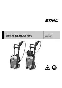
| Product type | High-pressure cleaner |
| Brand | STIHL |
| Model | RE 362 |
| Dimensions (L x W x H) | 735 x 570 x 1020 mm (operating position) |
| Height in transport position | 530 mm |
| Weight (with accessories) | Approx. 72 kg |
| Power supply | 400 V / 3~ / 50 Hz |
| Power consumption | 6.3 kW |
| Recommended fuse | 16 A (characteristic C or K) |
| Operating pressure | 3.5 - 18 MPa (35 - 180 bar) |
| Max. water flow rate | 1080 l/h |
| Max. feed water temperature | 60 °C (with pressure supply) |
| Detergent tanks | 2 tanks, dosage adjustment from 0 to 6% |
| Pressure and flow adjustment | On the device and on the gun (gradual) |
| High-pressure hose length | 10 m (metal braid, DN 08) |
| Sound pressure level | 76 dB(A) |
| Vibration level | < 2.5 m/s² |
| Safety devices | Discharge valve, automatic shut-off, gun lock |
| Pump oil | SAE 80W-90 API GL-5, quantity 730 ml |
| Regular maintenance | Check oil level, clean water inlet filter and nozzle |
| Spare parts | STIHL genuine parts recommended |
Frequently Asked Questions - RE 362 STIHL
User questions about RE 362 STIHL
0 question about this device. Answer the ones you know or ask your own.
Ask a new question about this device
Download the instructions for your Pressure washer in PDF format for free! Find your manual RE 362 - STIHL and take your electronic device back in hand. On this page are published all the documents necessary for the use of your device. RE 362 by STIHL.
USER MANUAL RE 362 STIHL
natural_image
White and black StoolawATER air purifier with hoses and control panel (no visible text or symbols)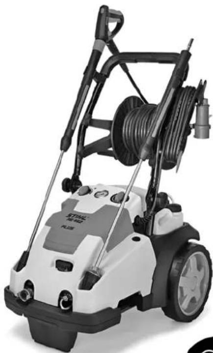
natural_image
Exterior view of a STIAL air purifier with attached hose and control panel (no visible text or symbols)Istruzioni d'uso
natural_image
Technical line drawing of a car's front and side views showing engine components (no text or symbols)natural_image
Technical diagram of a mechanical component with a cable inserted into a housing (no text or symbols visible)natural_image
Technical line drawing of a faucet assembly with valve parts (no text or symbols)natural_image
Technical line drawing of a mechanical component with a tool and arrow indicating assembly (no text or symbols)natural_image
Circular diagram with a stylized pen or tool inside, no text or symbols present.natural_image
Technical line drawing of a mechanical component with no visible text or symbolsnatural_image
Technical diagram of a mechanical component with no visible text or symbolsnatural_image
Line drawing of a vehicle's front wheel assembly with two wheels and a battery (no text or symbols)natural_image
Technical diagram of a mechanical component with a black knob and directional arrow (no text or symbols)natural_image
Diagram of a car engine cylinder connected to a water bottle, showing mechanical components and wiring (no text or symbols)$$ 1: 2 = 33, 3 \% $$
$$ 1: 3 = 25 \% $$
$$ 1: 5 = 16,6 \% $$
$$ 1: 1 0 = 9 \% $$
Beispiel:
natural_image
Mechanical assembly diagram showing a clamping device inserted into a housing (no text or symbols visible)natural_image
Diagram of a cable connector with a labeled component (no text or symbols present)natural_image
Line drawing of a pressure cooker with hoses and control panel (no text or symbols)natural_image
Mechanical assembly diagram showing a coiled cable with labeled component (no readable text or symbols)natural_image
Technical line drawing of a pressure cooker with hoses and wheels (no text or symbols)natural_image
Technical line drawing of a mechanical component with a central eye and directional arrow (no text or symbols)natural_image
Technical line drawing of a mechanical component with no visible text or symbols9937BA028 KN
natural_image
Diagram showing a cable being inserted into a pipe with a downward arrow indicating force (no text or symbols present)Guide to Using this Manual 37
Safety Precautions and Working Techniques 37
Tips for operation 44
Assembling the Unit 45
Transporting the Unit 45
Fitting, removing spray lance 47
Fitting, removing high-pressure hose 47
Connecting the water supply 48
Connecting to a pressureless water supply 49
Connecting to Power Supply 49
Switching On 50
Working 50
Adding detergent 52
Switching Off 54
After Finishing Work 54
Storing the Machine 55
Maintenance and Care 56
Maintenance 57
Checking the oil level 58
Oil change 58
First use after long periods of storage 59
Minimize Wear and Avoid Damage 59
Main Parts 60
Specifications 62
Special Accessories 64
Troubleshooting 65
Maintenance and Repairs 67
Disposal 67
EC Declaration of Conformity
67
Dear Customer,
Thank you for choosing a quality engineered STIHL product.
It has been built using modern production techniques and comprehensive quality assurance.
Every effort has been made to ensure your satisfaction and trouble-free use of the product.
Please contact your dealer or our sales company if you have any queries concerning this product.
Your

Dr. Nikolas Stihl
STIHL
This instruction manual is protected by copyright. All rights reserved, especially the rights to reproduce, translate and process with electronic systems.
Guide to Using this Manual Safety Precautions and Working Techniques
Pictograms
All the pictograms attached to the machine are shown and explained in this manual.
Symbols in text

WARNING
Warning where there is a risk of an accident or personal injury or serious damage to property.

NOTICE
Caution where there is a risk of damaging the machine or its individual components.
Engineering improvements
STIHL's philosophy is to continually improve all of its products. For this reason we may modify the design, engineering and appearance of our products periodically.
Therefore, some changes, modifications and improvements may not be covered in this manual.

Special safety precautions must be observed when using this machine because it uses electrical power.

It is important you read and understand the Instruction Manual before first use and keep the manual in a safe place for future reference. Non-observance of the Instruction Manual may result in serious or even fatal injury.

WARNING
- Children or youngsters should never be allowed to use the machine. Supervise children to ensure that they do not play with the machine.
- The machine should only be provided or loaned to people familiar with this model and its operation. The instruction manual should always be handed over with the machine.
- Do not use the machine if anyone not wearing protective clothing is in the working area.
- Before starting any work on the machine, e. g., cleaning, servicing, replacement of parts – unplug the power plug!
- Aerosols may form when using a high-pressure cleaner. Inhaling aerosols can be harmful to health. To determine the measures necessary for protection against aqueous aerosols, before starting work a risk assessment should be
English
carried out according to the surface to be cleaned and the surrounding area. Respiratory masks of class FFP2 or higher offer protection against aqueous aerosols.
Comply with national safety regulations issued, e.g. by employers' liability insurance associations, social security institutions, occupational safety and health authorities or other organizations.
When the machine is not in use, shut it off so that it does not endanger others. Ensure that the machine cannot be used without authorization; unplug the power plug.
The machine may only be used by persons who have been duly trained to use and handle it or who can demonstrate that they can operate the machine safely.
The machine can be used by persons with limited physical, sensory or mental capacity or with little experience and know-how as long as they are supervised and have been instructed on how to handle the machine safely and understand the associated risks.
The user is responsible for avoiding injury to third parties or damage to their property.
If you have not used this machine model before: Have your STIHL dealer or another expert show you how to use it safely.
In some countries, operation of machines that emit noise may be restricted by municipal regulations. Observe national regulations.
Always check that the machine is in good working order before starting work. Pay particular attention to the connecting cord, power plug, high-pressure hose, spray attachment and safety mechanisms.
Never operate the machine with a defective high-pressure hose – ensure that it is replaced immediately.
The machine may only be used when all parts are in perfect working order.
The high-pressure hose must not be driven over, pulled, buckled or twisted.
Do not use the high-pressure hose or connecting cord to pull or transport the machine.
The high-pressure hose must be approved for the permissible excess pressure of the machine.
The permissible excess pressure, the maximum permitted temperature and the date of manufacture are stated on the cladding of the high-pressure hose. The permissible pressure and date of manufacture are specified on the fittings.
Accessories and Spare Parts
WARNING
- High-pressure hoses, fittings and couplings are important for machine safety. Only high-pressure hoses, fittings, couplings and other accessories which have been approved by STIHL for this machine or technically equivalent parts may be mounted on the machine. If you have
any questions in this respect, consult a servicing dealer. Use only high-quality accessories. Otherwise, there may be a risk of accidents or damage to the unit.
- STIHL recommends the use of genuine STIHL parts and accessories. These have been optimized for the product and the user's requirements.
Do not modify the machine – otherwise the safety may be endangered. STIHL excludes all liability for personal injury and damage to property caused while using unauthorized attachments.
Physical suitability
The machine may only be operated by people who are rested, in good physical condition and mental health. If you have any condition that might be aggravated by strenuous work, check with your doctor before operating this machine.
Anyone who has consumed alcohol, medicines affecting their ability to react or drugs must not operate the machine.
Areas of application
The high-pressure cleaner can be used to clean surfaces, motor vehicles, machines, tanks, facades or stables and to remove rust without dust or sparks.
Other uses are not permitted and may lead to accidents or damage to the machine.
Do not operate the machine at temperatures near or below 0^ C ( 32^ F).
Clothing and equipment
Wear shoes with non-slip soles.
WARNING

To reduce the risk of eye injuries, wear tight-fitting safety goggles conforming to standard EN 166. Make sure that the safety goggles fit correctly.
Wear protective clothing. STIHL recommends that a boiler suit be worn in order to reduce the risk of injury due to accidental exposure to the high-pressure jet.
Transport
When transporting in and on vehicles:
- Secure the high-pressure cleaner in accordance with the regulations applicable in the country of use to prevent toppling over and damage
- Drain the detergent tank and secure it to prevent toppling over
English
Antifreeze is recommended if the machine and accessories are to be transported at temperatures near or below 0 °C (32 °F) - see "Storage".
Detergents
WARNING
- The machine was designed for use with the detergents offered or recommended by the manufacturer.
-
Use only detergents that are approved for use with high-pressure cleaners. Use of unsuitable detergents can cause damage to health, as well as to the machine and the object to be cleaned. If you have any questions in this respect, consult a servicing dealer.
-
Always use detergent in the specified dosage – follow the corresponding instructions for use of the detergent.
- Chemical detergents may contain physiologically harmful (toxic, caustic, irritant), flammable or explosive substances. In the event of skin or eye contact with detergent, flush the affected body parts with plenty of clean water immediately. If detergent is swallowed, seek medical attention immediately. Note the manufacturer's safety data sheets!
Before starting work
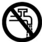
Do not connect the high-pressure cleaner directly to the drinking water main.
Only connect the high-pressure cleaner to the drinking water main in conjunction with a back flow preventer – see "Special accessories".
WARNING
- If drinking water has passed through the back flow preventer, it can no longer be regarded as drinking water.
Do not use the machine with dirty water.
If there is a risk that dirty water will occur (e. g., flowing sand), an appropriate water filter must be used.
Inspect the high-pressure cleaner
WARNING
- The high-pressure cleaner should only be used if it is in full working order and undamaged – risk of accident!
- It must be possible to move the switch to the 0 position easily
- The switch must be in the 0 position
-
Do not use the machine with a damaged high-pressure hose, spray attachment and safety devices
-
High-pressure hose and spray attachment in good condition (clean, moving easily) and correctly assembled
- For good control of the machine, the handles should be clean and dry with no oil or dirt on them
- Check oil level
- Never attempt to modify the controls or safety devices in any way
- Set up the machine so that it cannot slip or tip over. Only operate the machine on a stable and level ground
Electrical connection
WARNING
Minimize the risk of electrical shock:
- Voltage and frequency of the machine (see rating plate) must match the voltage and frequency of the mains supply
- Examine the connecting cord, power plug and extension cord for damage. Do not use the machine with a damaged connecting cord, extension cord or damaged power plug
- Only connect the machine to a correctly installed power socket
- The insulation on the connecting cord and any extension cord, the plug and the coupling must be fully intact
- Never touch the power plug, connecting cord and extension cord, and electrical plug connections with wet hands
WARNING
Route the connecting cord and extension cord properly:
- Observe the minimum cross-section of the individual cords – see "Connecting the machine to the power supply"
- Route and mark the power cord so that it cannot become damaged and no one is endangered – risk of stumbling!
- Use of unsuitable extension cords can be dangerous. Use only extension cords that are approved for outdoor use and are correspondingly marked and have a sufficient cross-section
- The connector and coupling of the extension cord must be waterproof and must not lie in water
- It is advisable to keep the plug connection at least 60 mm above the ground/floor, e. g. by using a cable reel
- Don't let the cord rub against edges or pointed or sharp objects
English
- Don't squeeze the cord under doors or windows
- If cords become snarled – unplug the power plug and unsnarl the cord
- Always unroll the power cord from the cable reel completely, to avoid risk of fire due to overheating.
During operation

WARNING
- Never draw in fluids containing solvents or undiluted acids and solvents (e. g., gasoline, heating oil, paint thinner or acetone). These substances damage the materials used in the machine. The spray is highly combustible, explosive and poisonous.
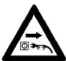
The plug must be disconnected immediately if the cord is damaged – danger of electrocution!
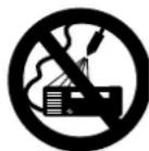
Never direct the high-pressure jet or water hose against the machine itself or against other electrical appliances and equipment – danger of short-circuiting!
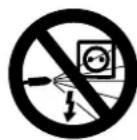
Never direct the high-pressure jet or water hose against electrical equipment, connections and power cords – danger of short-circuiting!
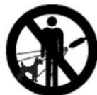
Never direct the high-pressure jet against yourself or other people, not even to clean clothing or shoes – risk of injury!
Ensure you always have a firm and safe footing.
The machine may only be operated in an upright position.
Beware of slipping on ice, water, snow or uneven ground!
Keep the high-pressure cleaner as far away as possible from the object being cleaned.
Do not cover the machine. Ensure adequate motor ventilation.
Do not direct the high-pressure jet toward animals.
Do not direct the high-pressure jet onto places you cannot see.
Keep children, animals and bystanders at a safe distance.
Hazardous substances (e. g. asbestos or oil) must not be allowed to escape into the environment unchecked when working with the machine. The applicable environmental regulations must be observed without fail.
Surfaces of asbestos cement must never be cleaned with a high-pressure jet. Hazardous, breathable asbestos fibers may be released in addition to the dirt. The danger is greatest when the washed surface has dried.
Delicate parts made of rubber, fabric or similar materials must not be cleaned with a pencil jet, e. g. from the rotary nozzle. Maintain a sufficient distance between the high-pressure hose and the surface when cleaning to avoid any damage to the surface being cleaned.
The trigger on the spray gun must move easily and automatically return to its starting position when released.
Hold the spray attachment firmly with both hands in order safely to withstand the kickback force and additional torque produced when using spray attachments with an angled spray lance.
Do not buckle or loop the high-pressure hose.
Ensure that the connecting cord and the high-pressure hose are not damaged by being driven over, squashed or pulled; protect them against heat and oil.
Do not touch the connecting cord with the high-pressure jet.
If the machine is subjected to a strain for which it was not designed (e. g., heavy impact or a fall), always check that it is in good condition before continuing work - refer also to the chapter "Before starting work". Also make certain that the safety mechanisms are working properly. Never continue using a machine that is not in perfect working order. In case of doubt, have the unit checked by your servicing dealer.
Before leaving the machine unattended: Switch off the machine – unplug the power plug.
Safety equipment
When the safety equipment is activated, excessive pressure is returned to the intake side of the pump via a safety valve. This safety feature has been set by the manufacturer and must not be adjusted.
After finishing work
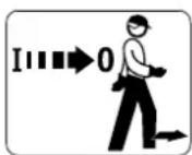
Switch off the machine before leaving it!
- Unplug the power plug from the socket
- Disconnect water intake hose between machine and water supply
Never unplug the power plug by pulling on the connecting cord: always grip the plug itself.
Maintenance and repairs

WARNING
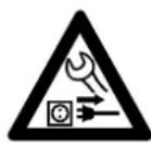
Before starting any work on the machine: Always disconnect the machine from the mains power supply.
- Use only high-quality spare parts. Otherwise, there may be a risk of accidents and damage to the unit. If you have any questions in this respect, consult a servicing dealer.
- To avoid risks, work on the machine (e. g. replacing a damaged power cord) may only be carried out by authorized dealers or qualified electricians.
English
Clean plastic parts with a cloth. Harsh detergents can damage the plastic.
Clean ventilation slots in motor housing as needed.
The machine must be serviced regularly. Do not attempt any maintenance or repair work not described in the Instruction Manual. All other work should be carried out by a servicing dealer.
STIHL recommends the use of genuine STIHL spare parts. Such parts have been optimized for the machine and the user's requirements.
STIHL recommends that maintenance and repair work be carried out only by authorized STIHL dealers. STIHL dealers receive regular training and are supplied with technical information.
Tips for operation
The following information and examples of application make work easier and contribute to achieving an optimum cleaning result.
Operating pressure and water throughput
High pressure dissolves dirt better. The higher the water throughput, the easier it is to remove the dirt that has been loosened.
Clean delicate parts and surfaces (e. g. car paint, rubber) by applying low pressure or at a greater distance to avoid damage. 100 bar pressure is sufficient for cleaning vehicles.
Nozzles
Fan-jet nozzle
All-purpose – to clean parts and (sensitive) surfaces.
Applications:
- Cleaning vehicles and machines
– Cleaning floors and surfaces - Cleaning roofs and facades
Rotary nozzle
To remove stubborn dirt on hard-wearing surfaces.
Extremely dirty surfaces
Soak extremely dirty surfaces with water before cleaning them.
Detergents:
The cleaning effect can be improved by using detergents. The corresponding exposure time (dependent on the detergent used) increases the cleaning performance.
Do not allow the detergent to dry.
Always use detergent in the specified dosage and follow the corresponding instructions for use of the detergent.
Mechanical cleaning:
The additional use of e. g. rotary nozzles or washing brushes helps to remove highly adhesive layers of dirt.
Assembling the Unit
Attach the connector to the water inlet (3/8" thread) before using it for the first time.
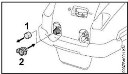
- Remove protective cap (1) to the water inlet
●Attach the connector (2) and tighten it by hand
Transporting the Unit
Fold-down pushbar
The pushbar can be folded down for compact transport in vehicles.
Do not reach within the swivel range of the pushbar – parts of your body may become jammed between the pushbar and housing if the pushbar is folded down.
Transport position
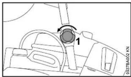
●Loosen knob (1) on both sides
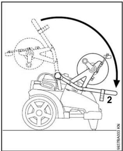
●Swing pushbar (2) downward as far as possible
Operational position
Only use the machine if the pushbar is folded out completely.
English
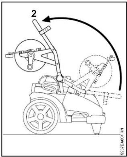
●Swing pushbar (2) upward as far as possible
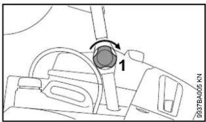
●Secure pushbar and knob (1) on both sides
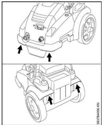
Carrying the machine
natural_image
Technical line drawings of a robotic car showing front and side views with arrows indicating motion (no text or symbols)Carry the machine by the handles as illustrated.
Pushing the machine
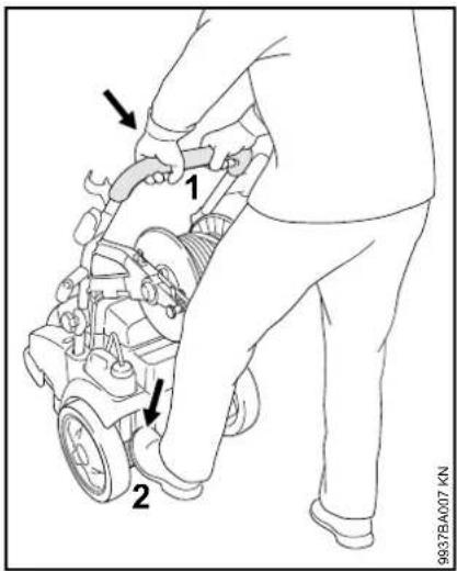
●Hold the machine firmly with both hands on the pushbar (1)
●Steady the machine with your foot on the kick plate (2), press pushbar (1) downward and balance the machine
Fitting, removing spray lance
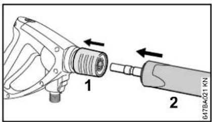
●Pull back and hold the coupling (1)
●Push the spray lance (2) into the mount on the spray gun, or pull it out to remove the spray gun, respectively
●Release the coupling (1)
Fitting, removing high-pressure hose
Machines without hose reel
Connecting the high-pressure hose
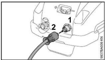
●Push high-pressure hose onto the connector (1)
●Attach union nut (2) and screw it on and tighten by hand
Disconnecting the high-pressure hose
●Unscrew the union nut (2)
●Pull high-pressure hose off of connector (1)
Machines with hose reel
The high-pressure hose is already connected at the factory.
Disconnecting the high-pressure hose
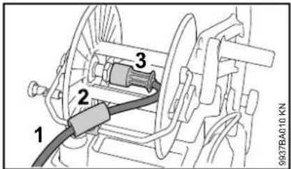
●Unroll the high-pressure hose (1)
●Open the hose guide (2)
●Unscrew the union nut (3).
●Pull high-pressure hose (1) off of connector
Connecting the high-pressure hose
●Push the high-pressure hose (1) onto the connector of the hose reel
●Attach union nut (3) and screw it on and tighten by hand
●Push the high-pressure hose into the hose guide (2) and close the hose guide.
●Roll up high-pressure hose
English
High-pressure hose and spray gun
Fitting
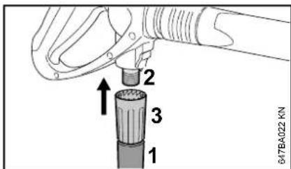
●Push the high-pressure hose (1) onto the connector (2)
●Attach union nut (3) and screw it on and tighten by hand
Removing
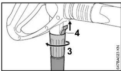
●Push the coupling (4) in the direction of the arrow and hold it
●Loosen the union nut (3) and unscrew it from the connector in the direction of the arrow
High-pressure hose extension
As a rule, always use only one high-pressure hose extension – see "Special accessories"
Connecting the water supply
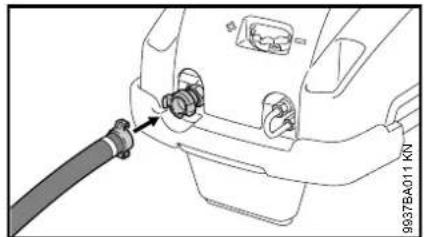
●Connecting the water hose Briefly rinse out the water hose before connecting it to the machine to prevent sand and other particles from entering the machine and to purge the air from the water hose.
| Diameter of water hose: 3/4" | |
| Length of water hose: | min. 10 m (to absorb pres-sure surges) |
| max. 25 m |
natural_image
Technical line drawing of a car front panel with a cable inserted into the connector (no text or symbols)●Mesh the jaws with each other and turn right as far as possible
●Turn on water supply
To vent the system:
●Actuate the spray gun (without spray lance mounted) until a uniform water jet emerges
Connection to the drinking water main
natural_image
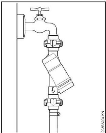
Technical line drawing of a pipe valve assembly with a valve and fittings (no text or symbols)When hooking up to the drinking water main, a backflow preventer must be installed between the water tap and the hose. The design of the backflow preventer must comply with the applicable country-specific regulations.
If drinking water has passed through the backflow preventer, it can no longer be regarded as drinking water.
Follow the rules laid down by the local water supply company to prevent water flowing back from the high-pressure cleaner into the drinking water main.
Connecting to a pressureless water supply
The high-pressure cleaner can only be used in suction operation with the suction set (special accessory).

NOTICE
As a rule, it is advisable to use a water filter.
- Connect the machine to the pressurized water supply and start it up briefly in accordance with the Instruction Manual
●Switch off the machine
●Disconnect the spray attachment from the high-pressure hose
●Unscrew the hose connector from the water connection - Connect the suction set to the water connection with the included connector
Always use the connector included in the suction set. The hose connectors included as standard with the high-pressure cleaner are not leakproof in suction operation and thus are not suitable for drawing in water.
- Fill the suction hose with water and immerse the suction cup of the suction hose in the water tank – do not use dirty water
●Hold down the high-pressure hose by hand
●Switching on the machine
●Wait until a steady jet exits the high-pressure hose
●Switch off the machine
●Connect spray attachment
●Switch on the machine with the spray gun open
●Actuate the spray gun several times briefly in order to bleed the air out of the machine as quickly as possible
●Switch off the machine
●Connect spray attachment
●Switch on the machine with the spray gun open
●Actuate the spray gun several times briefly in order to bleed the air out of the machine as quickly as possible
Connecting to Power Supply
The voltage and frequency of the machine (see rating plate) must match the voltage and frequency of the power connection.
The minimum fuse protection of the power connection must comply with the specifications – see "Specifications".
The machine must be connected to the power supply via an earth-leakage circuit breaker to disconnect the power supply if the differential current to earth exceeds 30 mA for 30 ms.
The power connection must correspond to IEC 60364-1 and relevant national regulations.
When the machine is switched on, voltage fluctuations that occur under unfavorable mains conditions (high power line impedance) may negatively affect other connected electrical appliances. Trouble is not anticipated at power line impedances less than 0.15 Ω.
The extension cord must have the following minimum cross-section depending on the mains voltage and cord length.
Cord length Minimum cross-section
| 400 V / 3~: | |
| up to 20 m 1.5 mm | ^2 |
| 20 m to 50 m 2.5 mm | ^2 |
| 230 V 3~: | |
| up to 20 m 2.5 mm | ^2 |
| 20 m to 50 m 4 mm | ^2 |
English
200 V / 3\~:
up to 10 m 3.5 mm 2
10 m to 30 m 5.5 mm ^2
Connection to the power supply socket
Before connection to the power supply, check that the machine is switched off – see "Switching off the machine"
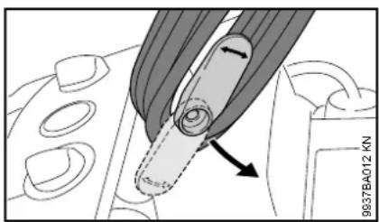
●Swivel the lower holder upward and remove the power cord
●Plug the power cord or extension cord into a properly installed outlet
Switching On

NOTICE
The machine may only be switched on when the water intake hose is connected and the water supply has been turned on. Otherwise the machine may be damaged due to lack of water.
●Turn on water supply
●Completely unroll the high-pressure hose
natural_image
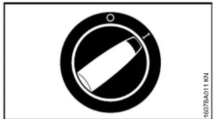
Circular diagram with a stylized pen-like shape inside, no text or symbols present.- Turn the master switch to I – now the machine is in standby mode Machine with hose reel

NOTICE
Always completely unroll the high-pressure hose from the hose reel. The high water pressure causes the high-pressure hose to expand. This can also damage the hose reel or high-pressure hose.
Working
Actuate the spray gun
●Direct the spray attachment towards the object to be cleaned
- Point the rotary nozzle downwards when starting (if fitted)
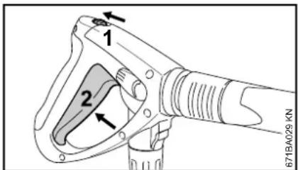
- Press the safety latch (1) in the direction of the arrow – the lever (2) is unlatched
- Squeeze the lever (2) The motor stops when the lever is released.
Pressure/quantity control on the machine
Working pressure and water flow rate can be set on the high-pressure pump for long-term adjustment in line with the cleaning job concerned.
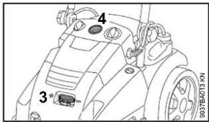
●Turn the knob (3) to set the working pressure and water flow rate
The pressure in the high-pressure pump is indicated by a pressure gauge (4).
The indicated pressure is not always the same as the pressure in the spray lance before the nozzle. The pressure before the nozzle depends on the position of the pressure/quantity control lever on the spray gun.
Pressure/quantity control on the spray gun
The working pressure and water volume can be set on the spray gun for short-term adjustment in line with the cleaning task.
Standard setting
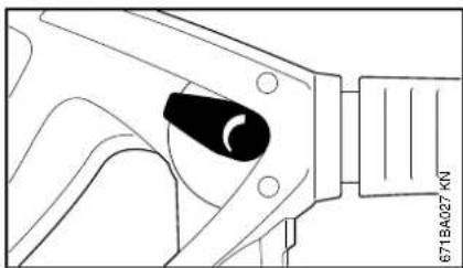
natural_image
Technical line drawing of a mechanical component with no visible text or symbolsMove the setting lever to standard position: Maximum working pressure and water flow rate.
Reduced working pressure and water flow rate
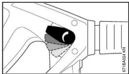
natural_image
Technical diagram of a mechanical component with no visible text or symbolsThe setting lever can be used to adjust the working pressure and water flow rate in fine increments.
Pressure control at the nozzle
The operating pressure can be infinitely adjusted at the nozzle.
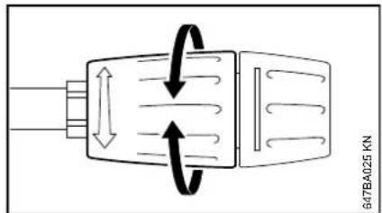
●Turn the nozzle sleeve – the quantity of water delivered remains unchanged
High-pressure hose
NOTICE
Do not buckle or loop the high-pressure hose.
Do not place any heavy objects on the high-pressure hose, and do not drive any vehicles over it.
Machines with hose reel
The high-pressure hose can be disconnected either from the front or back of the machine with the folding cliplock.
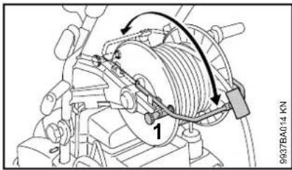
●Undo the hose reel brake (1)
●Fold the cliplock forward or backward
Standby mode
NOTICE
The machine must not be operated in standby mode for more than 5 minutes. If work is interrupted for more than 5 min., during breaks or if the machine is left unattended, switch off the machine at the master switch – see "Switching off the machine".
Only RE 462, RE 462 PLUS
Safety shutdown
If the switched on machine is not operated, it disconnects from the power mains automatically after 30 minutes.
English
Protection against inadvertent operation of the spray gun (e. g., by uninvolved persons).
To restart the machine, switch it off and then on again.
Motor coasting function
The pump continues to run without pressure in bypass mode for approx. 20 seconds after closing the spray gun before the motor switches off. This prevents the automatic cutoff device from unnecessarily actuating.
Adding detergent
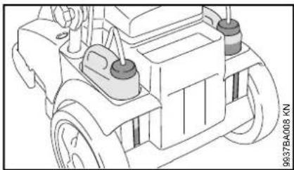
The machine is equipped with two detergent containers. Depending on use and detergent used, the feed can be changed between the two containers during operation.
natural_image
Technical line drawing of a vehicle chassis with wheels and components (no text or symbols)The filling level of each container can be read through the recesses in the housing.
If high-pressure hose extensions are connected, it is impossible to draw in detergent from the detergent container.
Detergent can only be drawn into the machine in low-pressure operation.
Preparations
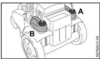
●Fill the respective detergent container A or B with STIHL detergent diluted as specified
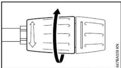
●Turn sleeve as far as possible in the direction of the arrow (low-pressure operation)
natural_image
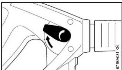
Technical diagram of a mechanical component with a black knob and directional arrow (no text or symbols)- Move the setting lever to standard position: Maximum working pressure and water flow rate
Using detergent from a separate container
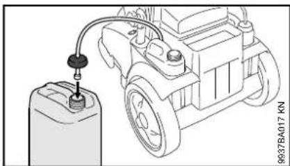
natural_image
Line drawing of a car engine with a fuel injector and cylinder, no text or symbols present●Unscrew the cap with intake hose from the detergent container
●Screw the cap with intake hose onto a separate detergent container
The cap has a standard thread and fits all standard detergent containers.
- Slide the intake hose as far as possible into the detergent container
Set the dosage
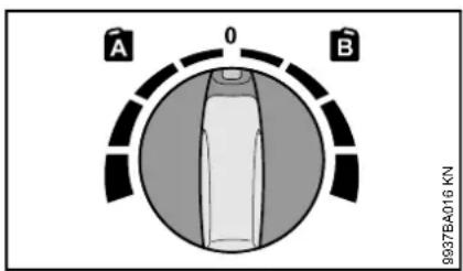
- Select the detergent container
- Detergent metering knob at setting A = left container
- Detergent metering knob at setting B = right container
●Set the dosage (possible adjustment range 0% - 6%)
●During use, always apply the detergent from the bottom upwards
Detergent must not be allowed to dry on the object to be cleaned.
If detergent is no longer to be added:
●Set detergent metering knob to 0
- Let the high-pressure cleaner continue to run with the spray gun open until no more detergent comes out of the nozzle
After finishing work
●Empty the detergent tank and rinse it with clear water
●Immerse the intake hose in clean water
●Actuate the spray gun and flush out the residual detergent
Precisely calculating/setting the detergent concentration
For a few detergents, the concentration must be very precisely set. In this case, measure water flow rate and consumption of cleaning agent.
- Set the nozzle sleeve to low-pressure operation – as described above
- Set the detergent metering knob to "0 % (min)"
●Hold the spray gun in a suitable empty receptacle (> 20 l) and actuate for exactly 1 minute
●Measure the quantity of water "Q" in the container - Fill 2 liters of detergent diluted as directed into a suitable container (with a scale of 0.1 l) – STIHL recommends the use of genuine STIHL detergents
●Hold the intake hose in the container - Set the detergent metering knob to the desired concentration: 0 % (min) bis 6 % (max)
●Hold the spray gun in a suitable empty receptacle (> 20 l) and actuate for exactly 1 minute
●Read the detergent consumption "QR" on the scale
Calculating the actual detergent concentration:
$$ \frac {\mathrm{QR}}{\mathrm{Q}} \times \mathrm{V} = \text { concentration } $$
- QR = amount of consumed detergent (in l/min)
- Q = Water without detergent (in l/min)
- V = Predilution of detergent (in %)
If the actual concentration deviates from the desired concentration, reset dosing knob and repeat measurement if necessary.
Calculating the predilution of the detergent in %
If the predilution is not indicated as a percentage, it can be calculated using the following table:
Ratio value
1:1 = 50 %
1:2 = 33.3 %
1:3 = 25 %
1:5 = 16.6 %
1:10 = 9 %
Example:
Calculation ratio of 1:2
- A = 1
- B = 2
English
$$ \frac {A}{(A + B)} \times 100 = \text { value in } \% $$
$$ \frac {1}{(1 + 2)} \times 100 = 33.3 \% $$
Switching Off
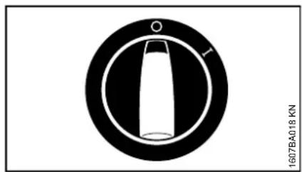
●Turn the master switch to 0
●Turn off water supply
●Actuate the spray gun until water only drips from the spray head (the machine is now depressurized)
●Release trigger
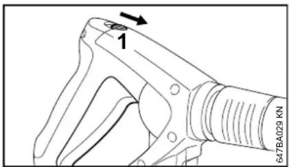
- Press the safety latch (1) in the direction of the arrow – the spray gun is locked to prevent inadvertent operation
●Unplug the power plug from the socket
●Disconnect water hose from the water supply and from the machine
After Finishing Work
Power cord

natural_image
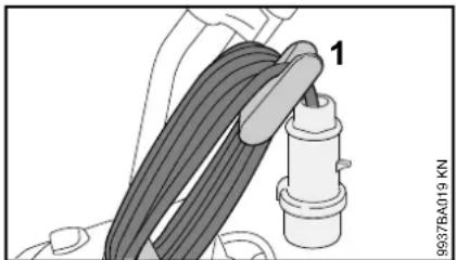
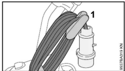
Mechanical assembly diagram showing a lever mechanism with a valve and housing (no text or symbols)●Roll up the power cord
natural_image
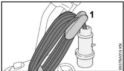
Mechanical assembly diagram showing a cable being inserted into a housing (no text or symbols visible)●Hang power cord on the holder (1)
High-pressure hose / spray attachment
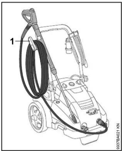
Machine without hose reel
natural_image
Line drawing of a pressure washer with hoses and a labeled component (no text or symbols on the device itself)●Roll up the high-pressure hose and hang it on the holder (2)
- Secure spray attachment in the holder
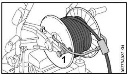
Machine with hose reel
natural_image
Mechanical assembly diagram showing a coiled cable with labeled component (no readable text or symbols)●Undo the hose reel brake (1)
●Roll up high-pressure hose
●Fit hose reel brake (1)
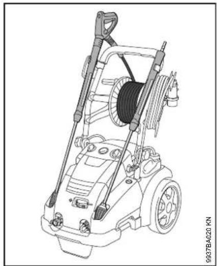
RE 362, RE 362 PLUS, RE 462, RE 462 PLUS
natural_image
Technical line drawing of a pressure cooker with attached suspension and coiled cable (no text or symbols)●Secure spray attachment in the holder
Storing the Machine
Store the machine in a dry room where it is protected from frost.
If protection from frost cannot be guaranteed, draw glycol-based antifreeze – like that used in motor vehicles – into the pump:
●Insert water intake hose in container with antifreeze
●Insert spray gun without spray lance in the same container
●Switch on the machine with the spray gun open
●Actuate the spray gun until a uniform jet emerges
- Keep leftover antifreeze in a sealed container
Maintenance and Care
| The following maintenance intervals apply in normal operating conditions. The specified intervals must be shortened accordingly for longer daily working hours. If the machine is only used occasionally, the intervals can be extended accordingly. | before starting work | at the end of work and/or daily | weekly or every 40 hours of operation | monthly | quarterly or every 200 hours of operation | every six months or every 500 hours of operation | if faulty | if damaged | as required | |
| Complete machine | Visual inspection (condition, leaks) X | |||||||||
| clean X | X | |||||||||
| Oil level of the high-pressure pump check | X | |||||||||
| Oil of the high-pressure pump change X | ||||||||||
| Connectors on high-pressure hose | clean X | X | ||||||||
| grease X | ||||||||||
| Plug-type coupling of the spray lance and the coupling sleeve of the spray gun | clean X | X | ||||||||
| Water intake strainer in the high-pressure inlet | clean X | X | ||||||||
| replace X | ||||||||||
| High pressure nozzle | clean X | |||||||||
| replace X | ||||||||||
| Ventilation openings clean X | ||||||||||
| Machine supports | check X | |||||||||
| replace X | ||||||||||
Maintenance
Always unplug the power cord before servicing or cleaning the machine.
In order to ensure trouble free operation, we recommend carrying out the following steps whenever the machine is used:
●Rinse the water hose, high-pressure hose, spray lance and accessories with water before fitting them
- Remove all sand and dust from the plug-type coupling of the spray lance and the coupling sleeve of the spray gun
Cleaning the high-pressure nozzle
Since the pump pressure increases if the nozzle is clogged, it must be cleaned immediately.
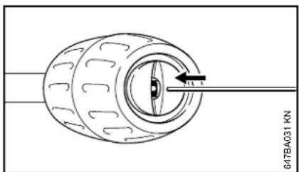
natural_image
Technical line drawing of a mechanical component with a central eye and directional arrow (no text or symbols)●Switch off the machine
- Actuate the spray gun until water merely drips from the spray head – the machine is now depressurized
- Remove spray lance
●Clean nozzle with a suitable needle
NOTICE
Always remove the spray lance before cleaning the nozzle.
●Rinse spray lance with water from the nozzle end
Cleaning the water intake screen
The water intake screen must be cleaned every week or more often if necessary.
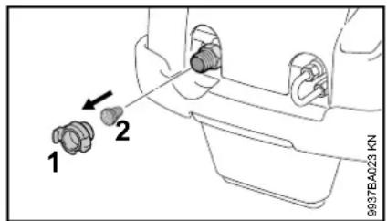
●Disconnect hose connector (1).
●Carefully release the wire retainer with pliers, remove the strainer (2) and rinse it
- Check if the strainer is undamaged – replace any damaged strainer
●Install strainer (2) and secure with wire retainer
Cleaning the ventilation openings
The machine must be kept clean so that cooling air can flow freely through the openings in the machine.
Lubricating the connections
Lubricate the connections on the high-pressure hose as needed
Checking the machine support
The front machine support must be replaced if damaged or worn, to ensure the stability of the machine.
English
Checking the oil level
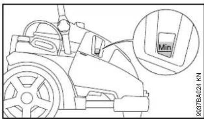
Check oil level weekly and after transport.
●Place the machine on a flat horizontal surface
- it must be between the "min" and "max" marks
- If necessary, add oil – see "Oil change")
Oil change
First oil change after 50 hours of operation, then every six months or every 500 hours of operation.
●Let the machine warm up
Fold out shroud
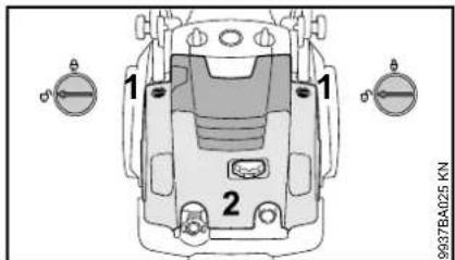
- Open lock (1) on both sides - setting
●Fold out shroud (2)
Drain oil
●Waste oil must be disposed of in accordance with the statutory regulations.
●Clean oil drain plug with a cloth to remove any metal chips
●Refit the oil drain plug
Fill with oil
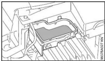
natural_image
Technical line drawing of a mechanical component with no visible text or symbols- Remove expansion tank cover
- Fill new oil into the expansion tank – see "Specifications"
- Close cover
- Close shroud and check oil level, add more oil if necessary
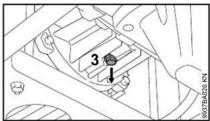
●Unscrew the oil drain plug (3)
●Drain oil into a suitable container (1 liter capacity at least)
First use after long periods of storage
During long periods of storage, mineral residue from the water may be deposited in the pump. This may cause the motor to start with difficulty or not at all.
- Connect the machine to the water supply and flush thoroughly with tap water, leave the power cord unplugged while doing so
●Plug the power plug into the wall socket
●Switch on the machine with the spray gun open
Minimize Wear and Avoid Damage
Compliance with the specifications of this owner's manual will avoid excessive wear and damage to the machine.
The machine must be used, maintained and stored as carefully as described in this owner's manual.
The user is responsible for all damage caused by failure to comply with the safety, operating and maintenance instructions. This applies in particular for:
– Product modifications not authorized by STIHL
- Use of accessories that are not approved for the machine, unsuitable or of inferior quality
– Use of the machine in a manner not in keeping with the intended use
– Use of the machine in sporting events or competitions
- Consequential damages due to continued use of a machine with defective components
– Damage due to freezing
– Damage due to improper power supply voltage
- Damage due to poor water supply (e.g., cross-section of the intake hose too small)
Maintenance work
All of the tasks listed under "Maintenance and Repairs" must be carried out periodically. If the user does
not carry out these maintenance tasks him- or herself, they should be delegated to a dealer.
STIHL recommends that maintenance and repair work be carried out only by authorized STIHL dealers. STIHL dealers receive regular training and are supplied with technical information.
If these tasks are not performed or are performed improperly, this may result in damage for which the user is responsible. Among other things, this includes:
- Damage to machine components due to delayed or insufficient performance of maintenance
- Corrosion damage and other consequential damages due to improper storage
- Damage to the machine as a result of using replacement parts of inferior quality
Wear parts
Some parts of the machine are subject to normal wear and tear even when the machine is used in conformity with its intended use. These parts must be replaced in due time, depending on the nature and duration of use. These include, among others:
– High-pressure nozzles
– High-pressure hoses
Main Parts
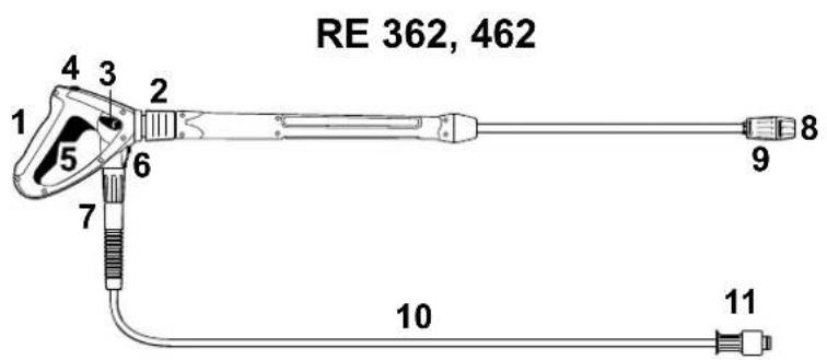
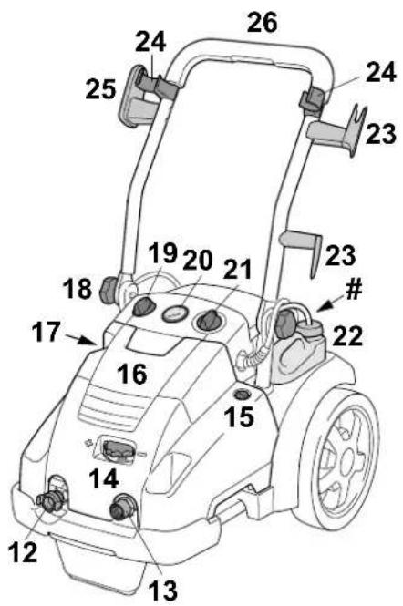
9937BA028 KN
1 Spray gun
2 Coupling for spray lance
3 Pressure and flow control setting lever
4 Safety catch
5 Lever
6 Safety latch for high-pressure hose
7 Union nut (connection of high-pressure hose and spray gun)
8 Nozzle
9 Nozzle sleeve for detergent intake
10 High-pressure hose
11 Union nut (connection of high-pressure hose and high-pressure cleaner)
12 Connector water intake
13 Connector high-pressure hose
14 Pressure/quantity control knob
15 Lock for shroud
16 Shroud
17 Oil level check
18 Knob
19 Detergent metering knob
20 Pressure gauge
21 Machine switch
22 Detergent tank
23 Bracket for power cord
24 Holders for spray attachment
25 Holder for high-pressure hose
26 Pushbar
Model plate
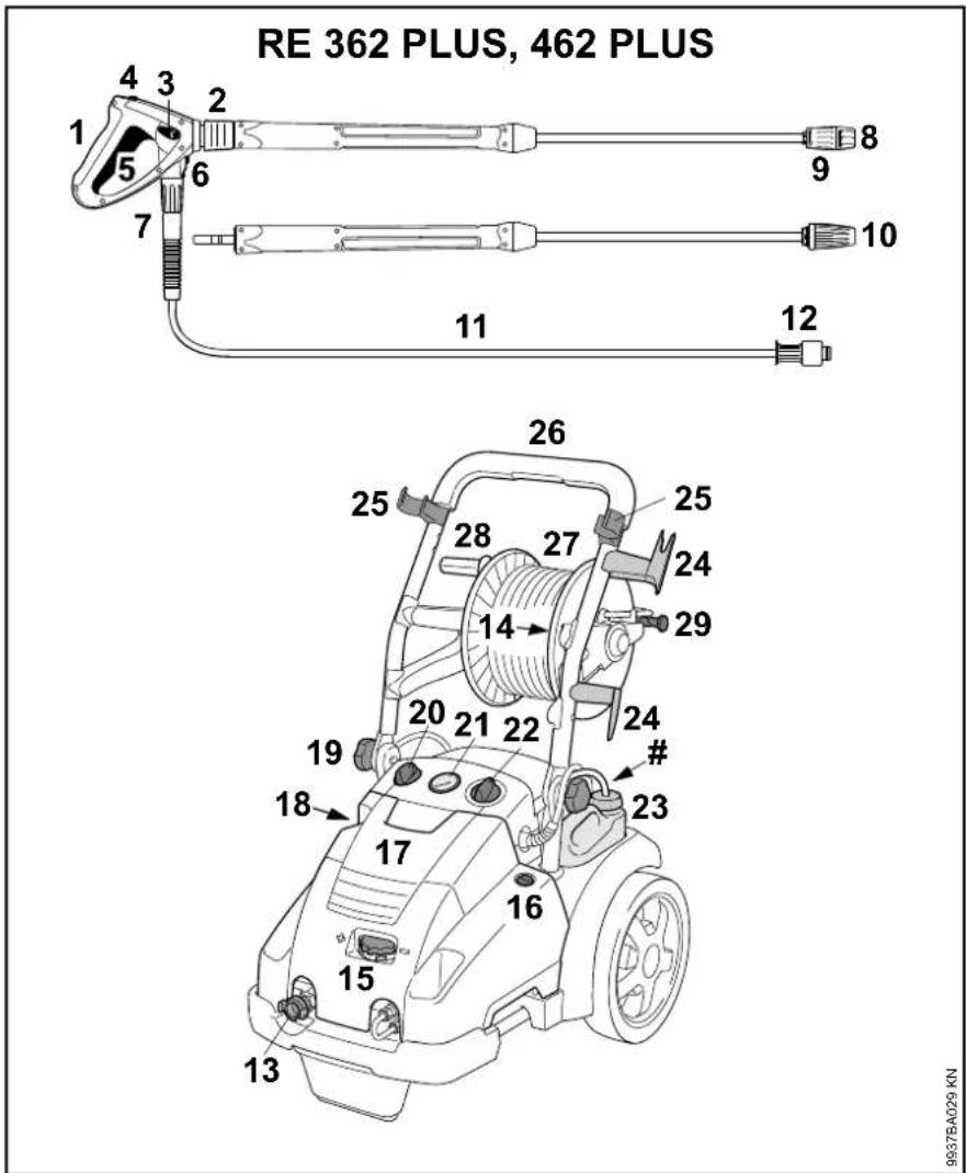
9937BA029 KN
1 Spray gun
2 Coupling for spray lance
3 Pressure and flow control setting lever
4 Safety catch
5 Lever
6 Safety latch for high-pressure hose
7 Union nut (connection of high-pressure hose and spray gun)
8 Nozzle
9 Nozzle sleeve for detergent intake
10 Rotary nozzle
11 High-pressure hose
12 Union nut (connection of high-pressure hose and high-pressure cleaner)
13 Connector water intake
14 Connector high-pressure hose
15 Pressure/quantity control knob
16 Lock for shroud
17 Shroud
18 Oil level check
19 Knob
20 Detergent metering knob
21 Pressure gauge
22 Machine switch
23 Detergent tank
24 Bracket for power cord
25 Holders for spray attachment
26 Pushbar
27 Hose reel
28 Crank handle for hose reel
29 Hose reel brake
Model plate
Specifications
Electrical Data
| RE 362 RE 362 PLUS RE 462 RE 462 PLUS | ||||
| Power supply: | 400 V / 3~ / 50 Hz | 400 V / 3~ / 50 Hz | 400 V / 3~ / 50 Hz | 400 V / 3~ / 50 Hz |
| 230 V / 3 / 50 Hz^1) | ||||
| Performance (EU) 2019/1781 §2(2) (j): | 6.3 kW | 6.5 kW | 7.4 kW | 7.4 kW |
| Fuse (characteristic "C" or "K"): 16 A 16 A / 25 A | 1) | 16 A 16 A | ||
| Protection class: I I I I | ||||
| Degree of protection: | IP X5 | IP X5 | IP X5 | IP X5 |
1) Norway only
Hydraulic specifications
| RE 362 RE 362 PLUS RE 462 RE 462 PLUS | ||||
| Working pressure: | 3.5 - 18 MPa(35 - 180 bar) | 3.5 - 18 MPa(35 - 180 bar) | 3.5 - 22 MPa(35 - 220 bar) | 3.5 - 22 MPa(35 - 220 bar) |
| Max. permissible pressure: | 25 MPa (250 bar) | 25 MPa (250 bar) | 25 MPa (250 bar) | 25 MPa (250 bar) |
| Max. water feed pressure: | 1 MPa (10 bar) | 1 MPa (10 bar) | 1 MPa (10 bar) | 1 MPa (10 bar) |
| Max. water throughput: | 1080 l/h | 1080 l/h | 1130 l/h | 1130 l/h |
| Water throughput as per EN 60335-2-79: | 1000 l/h | 1000 l/h | 1050 l/h | 1050 l/h |
| Max. suction lift: | 2.5 m | 2.5 m | 2.5 m | 2.5 m |
| Max. water feed temperature in the pressurized water supply: | 60 °C | 60 °C | 60 °C | 60 °C |
| Max. water feed temperature in suction operation: | 50 °C | 50 °C | 50 °C | 50 °C |
| Max. kickback force: | 51 N | 51 N / 49 N ^1) | 54 N | 54 N |
| Oil grade (service): | SAE 80W-90 API GL-5 | SAE 80W-90 API GL-5 | SAE 80W-90 API GL-5 | SAE 80W-90 API GL-5 |
| Oil capacity: | 730 ml | 730 ml | 730 ml | 730 ml |
1) Norway only
sample inspection
| RE 362 RE 362 PLUS RE 462 RE 462 PLUS | ||||
| Length approx.: | 735 mm | 890 mm | 735 mm | 890 mm |
| Width approx.: | 570 mm | 570 mm | 570 mm | 570 mm |
| Run height: | 1020 mm | 1020 mm | 1020 mm | 1020 mm |
| Transport position height: | 530 mm | 710 mm | 530 mm | 710 mm |
Weight
| RE 362 RE 362 PLUS RE 462 RE 462 PLUS | ||||
| With spray attachment and high-pressure hose: approx. | 72 kg | approx. 79 kg / approx. 80 kg1) | approx. 77 kg approx. 83 kg | |
1) Norway only
High-pressure hose
| RE 362 RE 362 PLUS RE 462 RE 462 PLUS | ||||
| Steel braiding | 10 m, DN 08 | 15 m, DN 08 | 10 m, DN 08 | 20 m, DN 08 |
English
Sound and vibration levels
Sound pressure level L_p to ISO 3744 (at a distance of 1 m)
RE 362, RE 362 PLUS: 76 dB(A)
RE 462, RE 462 PLUS: 75 dB(A)
Sound power level L_w to ISO 3744
RE 362, RE 362 PLUS: 87.5 dB(A)
RE 462, RE 462 PLUS: 86.5 dB(A)
Vibration level a_hv at the handle according to ISO 5349
RE 362, RE 362 PLUS: < 2.5 m/s ^4
RE 462, RE 462 PLUS: < 2.5 m/s ^4
The K-factor in accordance with Directive 2006/42/EC is 2.0 dB(A) for the sound pressure level and sound power level; the K-factor in accordance with Directive 2006/42/EC is 2.0 m/s ^2 for the vibration level.
REACH
REACH is an EC regulation and stands for the Registration, Evaluation, Authorisation and Restriction of Chemical substances.
For information on compliance with the REACH regulation (EC) No. 1907/2006 see www.stihl.com/reach.
Special Accessories
Pipe cleaning kit
in lengths 10 or 20 m
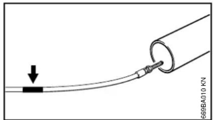
natural_image
Diagram showing a cable being inserted into a pipe with a downward arrow indicating force (no text or symbols present)There is a mark (arrow) at the end of the cleaning hose:
- Push the hose into the pipe to be cleaned until this mark is reached – then switch on the machine
When this mark appears as the hose is pulled out of the pipe:
●Switching off the machine
●Actuate the spray gun until the machine has been depressurized
●Pull the hose out of the pipe completely
The hose must never be pulled out of the pipe when the machine is switched on.
Other special accessories
Rotary washing brush – exchangeable brush insert.
Wash brush – for mounting on straight or angled spray lances.
Spray lance, straight – lengths 350, 500, 1070, 1800 or 2500 mm.
Spray lance, angled – length 1070 mm; spray lance, angled – do not direct around blind corners behind which other people may be concealed.
Rotary nozzle with spray lance – length 950 mm – for large areas and very stubborn dirt. (supplied as standard with PLUS models)
High-pressure hose extension – DN 08, connection M27x1.5 – steel braided, reinforced, lengths 10, 15 or 20 m. Always use only one high-pressure hose extension.
High-pressure hose adapter – connection M27x1.5 – for connection of high-pressure hose and high-pressure hose extension.
Adapter – for connection of accessories with screw coupling and spray guns with push-in coupling.
Sand and wet-blasting unit – for sand-blasting, e. g., stone or metal.
Water filter – for filtering water from the water main, as well as for use in pressureless suction operation.
Backflow preventer – Prevents the water from flowing back from the high-pressure cleaner into the drinking water main.
Suction set – professional version, 3/4", length 3 m.
Ask your STIHL servicing dealer for current information about this and other special accessories.
Troubleshooting
| Before working on the machine, unplug the power cord, turn off the water supply and actuate the spray gun until the pressure has been relieved. | ||
| Fault Cause Remedy | ||
| Motor does not run when switched on (hums when switched on) | Mains voltage is too low or improper Check ele | electrical connectionCheck plug, cable and switch |
| Cable extension with wrong cross-section | Use an extension cord with a sufficient cross-section, see "Connecting the machine to the power supply" | |
| Cable extension too long Connect the machine | without an extension cord or with a shorter one | |
| Electric circuit-breaker has been tripped Switch | off the appliance, operate the spray gun until water only drips from the spray head, insert the safety lever, switch on the mains fuse | |
| Spray gun not actuated Actuate spray gun when switching on the machine | ||
| Motor constantly switches on and off | High-pressure pump or spray attachment is leaky | Have the machine checked by a servicing dealer 1) |
| The engine stops Machine switches off | because the motor is overheating | Check whether the supply voltage and machine voltage match; let the motor cool down for at least 5 minutes |
| Weak, ragged, unclean jet | Nozzle fouled | Clean nozzle, see "Maintenance" |
| Pressure fluctuates or drops | Insufficient water | Open water tap completely comply with permissible suction lift (suction mode only) |
| High-pressure nozzle in spray head is dirty | Clean high-pressure nozzle; see "Maintenance" | |
| Water intake strainer in pump inflow clogged | Clean water intake strainer; see "Maintenance" | |
| High-pressure pump is leaky, valves are defective | Have the machine checked by a servicing dealer 1) | |
| Nozzle clogged | Clean the nozzle | |
English
| Before working on the machine, unplug the power cord, turn off the water supply and actuate the spray gun until the pressure has been relieved. | ||
| Fault Cause Remedy | ||
| No detergents Detergent tank is empty | Top up the detergent container | |
| Detergent intake is clogged Eliminate clog | ||
| Venturi nozzle is worn Have the machine serviced by a dealer | ||
Maintenance and Repairs Disposal
Users of this machine may only carry out the maintenance and service work described in this user manual. All other repairs must be carried out by a servicing dealer.
STIHL recommends that you have servicing and repair work carried out exclusively by an authorized STIHL servicing dealer. STIHL dealers are regularly given the opportunity to attend training courses and are supplied with the necessary technical information.
When repairing the machine, only use replacement parts which have been approved by STIHL for this power tool or are technically identical. Only use high-quality replacement parts in order to avoid the risk of accidents and damage to the machine.
STIHL recommends the use of original STIHL replacement parts.
Original STIHL parts can be identified by the STIHL part number, the STIHL logo and the STIHL parts symbol (the symbol may appear alone on small parts).

High-pressure cleaner, accessories and packaging must be collected and recycled in an environmentally beneficial manner.
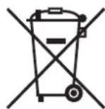
Do not dispose of high-pressure cleaner, accessories and packaging as household waste.

Information concerning disposal is available from a STIHL servicing dealer.
●High-pressure cleaner, accessories and packaging must be disposed of in accordance with the regulations and in an environmentally beneficial manner.
EC Declaration of Conformity
declare under our sole responsibility that
Designation: High-pressure
washer
Make: STIHL
Series: RE 362, RE 362
PLUS
Serial identification 4780
number:
Series: RE 462,
RE 462 PLUS
Serial identification 4780
number:
conforms to the relevant provisions of Directives 2011/65/EC, 2006/42/EU, 2014/30/EC and 2009/125/EU and has been developed and manufactured in compliance with the following standards in the versions valid on the date of production:
EN ISO 12100-1, EN ISO 12100-2, EN 55014-1, EN 55014-2, EN 60335-1, EN 60335-2-79, EN 61000-3-2, EN 61000-3-11
The measured and the guaranteed sound power level have been determined in accordance with Directive 2000/14/EC, Annex V, and standard ISO 3744.
Measured sound power level
RE 362, RE 362 PLUS: 87.5 dB(A)
RE 462, RE 462 PLUS: 86.5 dB(A)
English
Guaranteed sound power level
RE 362, RE 362 PLUS: 89 dB(A)
RE 462, RE 462 PLUS: 88 dB(A)
Technical documents deposited at:
The year of construction, the country of manufacture and the machine number are shown on the machine.
Head of Product Data, Regulations and Licensing

Table des matières
natural_image
Technical line drawings of a robotic car showing front and side views with arrows indicating motion (no text or symbols)natural_image
Diagram of a connector with a cable inserted into a device (no text or symbols visible)natural_image
Technical line drawing of a faucet assembly with valve parts (no text or symbols)natural_image
Circular diagram with a stylized pen-like shape inside, no text or symbols present.natural_image
Technical line drawing of a mechanical component with no visible text or symbolsnatural_image
Technical diagram of a mechanical component with highlighted internal area and mounting holes (no text or symbols)natural_image
Line drawing of a vehicle's front wheel assembly with no visible text or symbolsnatural_image
Technical diagram of a mechanical component with a black knob and directional arrow (no text or symbols)natural_image
Line drawing of a car engine cylinder connected to a fuel can (no text or symbols)$$ \frac {Q R}{Q} \times V = \text { concentration } $$
$$ 1: 2 = 33, 3 \% $$
$$ 1: 3 = 25 \% $$
$$ 1: 5 = 16,6 \% $$
$$ 1.10 = 9 \% $$
Exemple :
natural_image
Technical line drawing of a mechanical tool or device with no visible text or symbolsnatural_image
Illustration of a medical or laboratory procedure showing a tool inserted into a device (no text or symbols visible)natural_image
Diagram of a cable connector with a labeled component (no text or symbols beyond label)natural_image
Line drawing of a pressure washer with hoses and control panel (no text or symbols)natural_image
Mechanical assembly diagram showing a coiled cable with labeled component (no readable text or symbols)natural_image
Technical line drawing of a pressure cooker with hoses and suspension components (no text or symbols)natural_image
Technical line drawing of a mechanical component with a central eye and directional arrow (no text or symbols)natural_image
Technical line drawing of a vehicle chassis with internal components and exhaust pipes (no text or symbols)9937BA028 KN
natural_image
Diagram showing a cable being inserted into a pipe with a downward arrow indicating force (no text or symbols present)natural_image
Technical line drawings of a robotic car showing front and side views with arrows indicating motion (no text or symbols)natural_image
Technical diagram of a mechanical component with a cable inserted into a housing (no text or symbols visible)natural_image
Technical line drawing of a faucet assembly with valve and pipe (no text or symbols)natural_image
Circular diagram with a stylized pen or tool icon, no text or symbols presentnatural_image
Technical line drawing of a mechanical component with no visible text or symbolsnatural_image
Technical diagram of a mechanical component with no visible text or symbolsnatural_image
Technical line drawing of a vehicle's front wheel assembly (no text or symbols)natural_image
Technical diagram of a mechanical component with a black knob and directional arrow (no text or symbols)natural_image
Line drawing of a car engine with a fuel injector and tank (no text or symbols)$$ 1: 2 = 33, 3 \% $$
$$ 1: 3 = 25 \% $$
$$ 1: 5 = 16,6 \% $$
$$ 1: 10 = 9 \% $$
Ejemplo:
natural_image
Simple circular diagram with a vertical tube inside, no text or symbols present.1607BA018 KN
natural_image
Mechanical assembly diagram showing a tool interacting with a component (no text or symbols visible)natural_image
Mechanical assembly diagram showing a cable being inserted into a housing (no text or symbols visible)natural_image
Line drawing of a pressure cooker with hoses and labeled component (no text or symbols on the device itself)natural_image
Mechanical assembly diagram showing a coiled cable with labeled component (no readable text or symbols)natural_image
Technical line drawing of a pressure cooker with hoses and control panel (no text or symbols)natural_image
Technical line drawing of a mechanical component with no visible text or symbols9937BA028 KN
natural_image
Diagram showing a cable being inserted into a pipe with a downward arrow indicating force (no text or symbols present)natural_image
Technical diagram of a vehicle interior showing a circular component with directional arrow and part number 9937BA002 KN (no readable text or symbols)natural_image
Diagram of a vehicle's wheel and steering wheel assembly (no text or symbols)natural_image
Technical line drawings of a robotic car showing front and side views with arrows indicating motion (no text or symbols)natural_image
Technical line drawing of a mechanical component with a cable inserted into a housing (no text or symbols visible)natural_image
Technical line drawing of a faucet assembly with valve parts (no text or symbols)natural_image
Technical line drawing of a mechanical component with a tool and arrow indicating assembly (no text or symbols)natural_image
Circular diagram with a stylized pen or tool inside, no text or symbols presentnatural_image
Technical line drawing of a mechanical component with no visible text or symbolsnatural_image
Technical diagram of a mechanical component with internal layered structure (no text or symbols)natural_image
Technical line drawing of a vehicle chassis with wheels and a handle (no text or symbols)natural_image
Technical diagram of a mechanical component with a black arrow indicating rotation or movement (no text or symbols present)natural_image
Line drawing of a car engine with a fuel injector and a gas cylinder (no text or symbols)natural_image
Mechanical assembly diagram showing a clamping tool interacting with a motor (no text or symbols visible)●Avvolgere il cavo
natural_image
Mechanical assembly diagram showing a cable being inserted into a housing (no text or symbols visible)natural_image
Line drawing of a pressure cooker with hoses and control panel (no text or symbols)natural_image
Mechanical assembly diagram showing a coiled cable with labeled component 1 (no text or symbols beyond label)natural_image
Technical line drawing of a pressure washer with hoses and a coiled cable (no text or symbols)natural_image
Technical line drawing of a mechanical component with a central eye and directional arrow (no text or symbols)natural_image
Technical line drawing of a mechanical component with internal structure and ventilation duct (no text or symbols)9937BA028 KN
natural_image
Diagram showing a cable being inserted into a pipe with a downward arrow indicating force (no text or symbols present)natural_image
Technical diagram of a vehicle's wheel and steering wheel assembly (no text or symbols)natural_image
Technical line drawings of a robotic car showing front and side views with arrows indicating motion (no text or symbols)natural_image
Technical diagram of a mechanical component with a cable inserted into a housing (no text or symbols visible)natural_image
Technical line drawing of a faucet assembly with valve and pipe (no text or symbols)natural_image
Technical line drawing of a mechanical component with a tool and arrow indicating assembly (no readable text or symbols)natural_image
Circular diagram with a stylized pen or tool icon, no text or symbols presentnatural_image
Technical line drawing of a mechanical component with no visible text or symbolsnatural_image
Technical diagram of a mechanical component with no visible text or symbolsSó as RE 462, RE 462 PLUS
natural_image
Technical line drawing of a vehicle's front wheel assembly (no text or symbols)natural_image
Technical diagram of a mechanical component with a black knob and directional arrow (no text or symbols)natural_image
Line drawing of a car engine with a fuel injector and tank (no text or symbols)natural_image
Mechanical assembly diagram showing a tool interacting with a component (no text or symbols visible)natural_image
Mechanical assembly diagram showing a cable being inserted into a housing (no text or symbols visible)natural_image
Line drawing of a pressure washer with hoses and a labeled component (no text or symbols on the device itself)natural_image
Mechanical assembly diagram showing a coiled cable with labeled component 1 (no text or symbols beyond label)natural_image
Technical line drawing of a pressure cooker with hoses and wheels (no text or symbols)natural_image
Technical line drawing of a mechanical component with an arrow indicating direction (no text or symbols)Lubrificar as uniões
natural_image
Technical line drawing of a mechanical component with no visible text or symbols9937BA028 KN
natural_image
Diagram showing a cable being inserted into a pipe with a downward arrow indicating force (no text or symbols present)natural_image
Technical line drawings of a robotic car showing front and side views with arrows indicating motion (no text or symbols)●Hogedrukslang (1) afrollen
●Slanggeleiding (2) openmaken
natural_image
Technical line drawing of a mechanical component with a blue cable inserted into a housing (no text or symbols visible)natural_image
Technical line drawing of a faucet assembly with valve parts (no text or symbols)natural_image
Technical line drawing of a mechanical component with a tool and arrow indicating assembly (no readable text or symbols)natural_image
Circular diagram with a stylized pen or tool inside, no text or symbols present.natural_image
Technical line drawing of a mechanical component with no visible text or symbolsnatural_image
Technical diagram of a mechanical component with internal layered structure (no text or symbols)natural_image
Line drawing of a vehicle's front wheel assembly with two side-mounted sensors (no text or symbols)natural_image
Technical diagram of a mechanical component with a black knob and directional arrow (no text or symbols)natural_image
Technical line drawing of a car engine cylinder connected to a water bottle (no text or symbols)$$ 1: 2 = 33, 3 \% $$
Nederlands
$$ 1: 3 = 25 \% $$
$$ 1: 5 = 16,6 \% $$
$$ 1: 10 = 9 \% $$
Voorbeeld:
natural_image
Mechanical assembly diagram showing a lever mechanism with a cylindrical component and connecting parts (no text or symbols)●Netkabel opwikkelen
natural_image
Mechanical assembly diagram showing a cable being inserted into a housing (no text or symbols visible)natural_image
Line drawing of a power washer with hoses and a labeled component (no text or symbols on the diagram itself)natural_image
Mechanical assembly diagram showing a coiled cable with labeled component (no readable text or symbols)natural_image
Technical line drawing of a pressure cooker with attached suspension and motor (no text or symbols)natural_image
Technical line drawing of a mechanical component with a central eye and directional arrow (no text or symbols)natural_image
Technical line drawing of a mechanical component with no visible text or symbols9937BA028 KN
natural_image
Diagram showing a cable being inserted into a pipe with a downward arrow indicating force (no text or symbols present)natural_image
Technical diagram of a vehicle interior showing steering wheel and dashboard (no text or symbols)natural_image
Technical line drawings of a mechanical device showing front and side views with arrows indicating components (no text or symbols)natural_image
Technical diagram of a connector with a cable inserted, showing ports and wiring (no text or symbols)natural_image
Technical line drawing of a faucet assembly with valve and pipe (no text or symbols)natural_image
Technical diagram of a mechanical component with a tool and arrow indicating direction (no readable text or symbols)natural_image
Circular diagram with a stylized pen or tool icon, no text or symbols presentnatural_image
Technical line drawing of a mechanical component with no visible text or symbolsnatural_image
Technical diagram of a mechanical component with internal layered structure (no text or symbols)natural_image
Technical line drawing of a vehicle's front wheel assembly (no text or symbols)natural_image
Technical diagram of a mechanical component with a black knob and directional arrow (no text or symbols)natural_image
Line drawing of a car being connected to a fuel can, showing mechanical components and wiring (no text or symbols)natural_image
Mechanical assembly diagram showing a clamping tool interacting with a motor (no text or symbols visible)natural_image
Diagram of a cable connector with a labeled component (no text or symbols beyond label)natural_image
Technical line drawing of a pressure washer with hoses and control panel (no text or symbols)natural_image
Mechanical assembly diagram showing a coiled cable with labeled component (no readable text or symbols)natural_image
Technical line drawing of a pressure washer with attached hoses and wheels (no text or symbols)natural_image
Technical line drawing of a mechanical component with a central eye and directional arrow (no text or symbols)natural_image
Technical line drawing of a mechanical component with no visible text or symbols9937BA028 KN
natural_image
Diagram showing a cable being inserted into a pipe with a downward arrow indicating force (no text or symbols present)0458-681-9021-B

- STIHL
- Guide to Using this Manual Safety Precautions and Working Techniques
- Pictograms
- Symbols in text
- WARNING
- NOTICE
- Engineering improvements
- English
- Accessories and Spare Parts
- Physical suitability
- Areas of application
- Clothing and equipment
- Transport
- Detergents
- Before starting work
- Electrical connection
- During operation
- Safety equipment
- After finishing work
- Maintenance and repairs
- Tips for operation
- Nozzles
- Extremely dirty surfaces
- Detergents:
- Assembling the Unit
- Transporting the Unit
- Fold-down pushbar
- Operational position
- Fitting, removing high-pressure hose
- High-pressure hose and spray gun
- High-pressure hose extension
- Connecting the water supply
- Connection to the drinking water main
- Connecting to a pressureless water supply
- Connecting to Power Supply
- Connection to the power supply socket
- Switching On
- Working
- Actuate the spray gun
- Motor coasting function
- Adding detergent
- Set the dosage
- Precisely calculating/setting the detergent concentration
- Calculating the predilution of the detergent in %
- Ratio value
- Example:
- High-pressure hose / spray attachment
- Storing the Machine
- Maintenance
- Cleaning the high-pressure nozzle
- Cleaning the water intake screen
- Cleaning the ventilation openings
- Lubricating the connections
- Checking the machine support
- Checking the oil level
- Oil change
- Fold out shroud
- Drain oil
- Fill with oil
- First use after long periods of storage
- Minimize Wear and Avoid Damage
- Maintenance work
- Wear parts
- Main Parts
- Model plate
- Specifications
- Sound and vibration levels
- REACH
- Special Accessories
- Pipe cleaning kit
- Other special accessories
- Maintenance and Repairs Disposal
- EC Declaration of Conformity
- Table des matières
- Exemple :
- Lubrificar as uniões
- Nederlands
- Voorbeeld:
Brand : STIHL
Model : RE 362
Category : Pressure washer