ZENITH PRF0183060 - Basket ELICA - Free user manual and instructions
Find the device manual for free ZENITH PRF0183060 ELICA in PDF.
Download the instructions for your Basket in PDF format for free! Find your manual ZENITH PRF0183060 - ELICA and take your electronic device back in hand. On this page are published all the documents necessary for the use of your device. ZENITH PRF0183060 by ELICA.
USER MANUAL ZENITH PRF0183060 ELICA
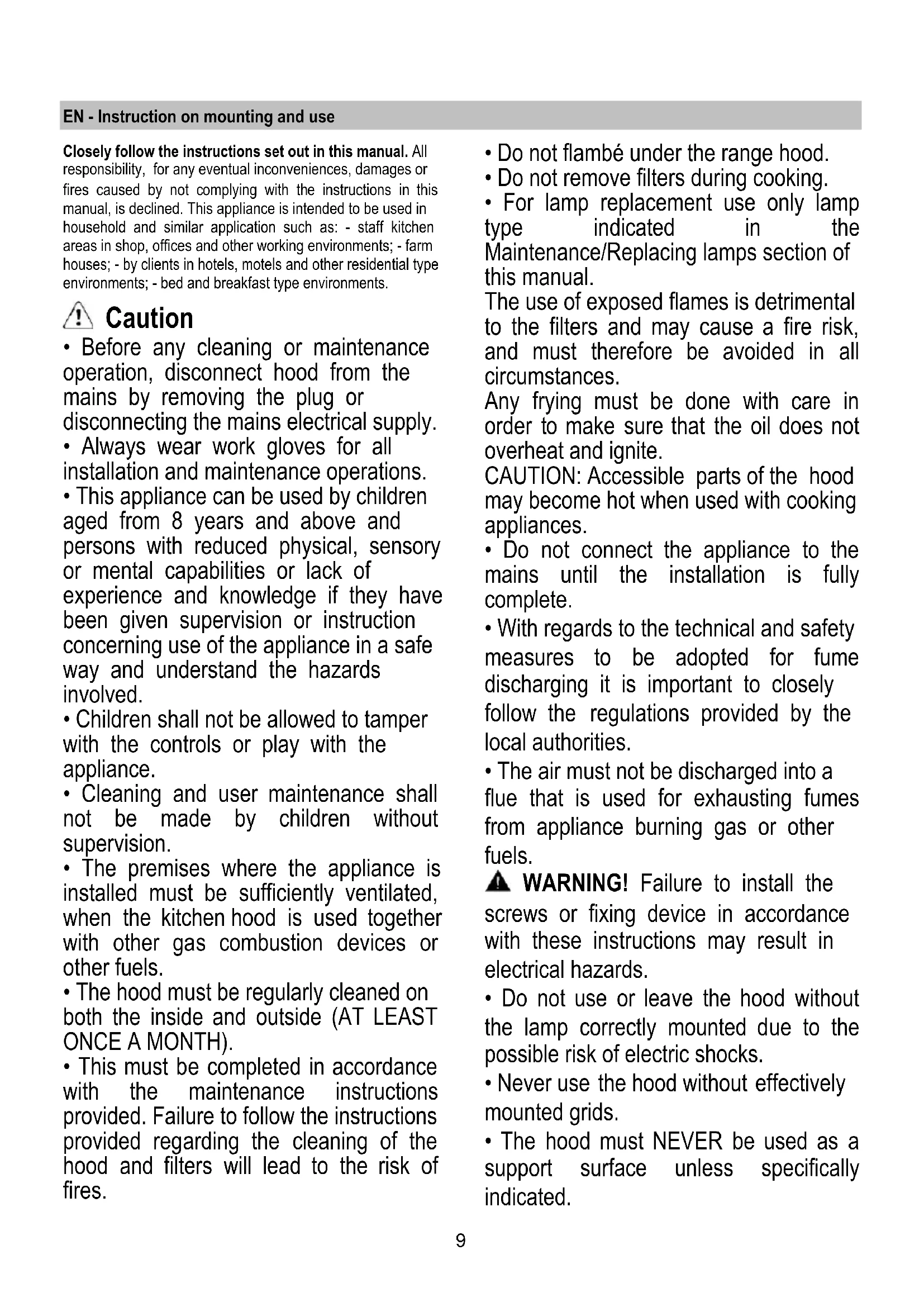
- Before any cleaning or maintenance operation, disconnect hood from the mains by removing the plug or disconnecting the mains electrical supply.
- Always wear work gloves for all installation and maintenance operations.
- This appliance can be used by children aged from 8 years and above and persons with reduced physical, sensory or mental capabilities or lack of experience and knowledge if they have been given supervision or instruction concerning use of the appliance in a safe way and understand the hazards involved.
- Children shall not be allowed to tamper with the controls or play with the appliance.
- Cleaning and user maintenance shall not be made by children without supervision.
- The premises where the appliance is installed must be sufficiently ventilated, when the kitchen hood is used together with other gas combustion devices or other fuels.
- The hood must be regularly cleaned on both the inside and outside (AT LEAST ONCE A MONTH).
- This must be completed in accordance with the maintenance instructions provided. Failure to follow the instructions provided regarding the cleaning of the hood and filters will lead to the risk of fires.
- Do not flambé under the range hood.
- Do not remove filters during cooking.
- For lamp replacement use only lamp type indicated in the Maintenance/Replacing lamps section of this manual. The use of exposed flames is detrimental to the filters and may cause a fire risk, and must therefore be avoided in all circumstances. Any frying must be done with care in order to make sure that the oil does not overheat and ignite. CAUTION: Accessible parts of the hood may become hot when used with cooking appliances.
- Do not connect the appliance to the mains until the installation is fully complete.
- With regards to the technical and safety measures to be adopted for fume discharging it is important to closely follow the regulations provided by the local authorities.
- The air must not be discharged into a flue that is used for exhausting fumes from appliance burning gas or other fuels. WARNING! Failure to install the screws or fixing device in accordance with these instructions may result in electrical hazards.
- Do not use or leave the hood without the lamp correctly mounted due to the possible risk of electric shocks.
- Never use the hood without effectively mounted grids.
- The hood must NEVER be used as a support surface unless specifically indicated.10
- Use only the fixing screws supplied with the product for installation or, if not supplied, purchase the correct screws type.
- Use the correct length for the screws which are identified in the Installation Guide.
- In case of doubt, consult an authorized service assistance center or similar qualified person. WARNING! Do not use with a programmer, timer, separate remote control system or any other device that switches on automatically. Electrical connection The mains power supply must correspond to the rating indicated on the plate situated inside the hood. If provided with a plug connect the hood to a socket in compliance with current regulations and positioned in an accessible area, after installation. If it not fitted with a plug (direct mains connection) or if the plug is not located in an accessible area, after installation, apply a double pole switch in accordance with standards which assures the complete disconnection of the mains under conditions relating to over-current category III, in accordance with installation instructions. WARNING! Before re-connecting the hood circuit to the mains supply and checking the efficient function, always check that the mains cable is correctly assembled. WARNING! If the supply cord is damaged, it must be replaced by the manufacturer, its service agent or similarly qualified persons in order to avoid hazard. Installation
- The minimum distance between the supporting surface for the cooking equipment on the hob and the lowest part of the range hood must be not less than 60cm from electric cookers and 65cm from gas or mixed cookers. If the instructions for installation for the gas hob specify a greater distance, this must be adhered to.
- This appliance is marked according to the European directive 2012/19/EC - UK SI 2013 No.3113 on Waste Electrical and Electronic Equipment (WEEE).
- By ensuring this product is disposed of correctly, you will help prevent potential negative consequences for the environment and human health, which could otherwise be caused by inappropriate waste handling of this product.
- The symbol on the product, or on the documents accompanying the product, indicates that this appliance may not be treated as household waste. Instead it should be taken to the appropriate collection point for the recycling of electrical and electronic equipment. Disposal must be carried out in accordance with local environmental regulations for waste disposal.
- For further detailed information regarding the process, collection and recycling of this product, please contact the appropriate department of your local authorities or the local department for household waste or the shop where you purchased this product. Appliance designed, tested and manufactured according to:
- EMC: EN 55014-1; CISPR 14-1; EN 55014-2; CISPR 14-2; EN/IEC 61000-3-2; EN/IEC 61000-3-3. Suggestions for a correct use in order to reduce the environmental impact: Switch ON the hood at minimum speed when you start cooking and kept it running for few minutes after cooking is finished. Increase the speed only in case of large amount of smoke and vapor and use boost speed(s) only in extreme situations. Replace the charcoal filter(s) when necessary to maintain a good odor reduction efficiency. Clean the grease filter(s) when necessary to maintain a good grease filter efficiency. Use the maximum diameter of the ducting system11 indicated in this manual to optimize efficiency and minimize noise. Use The hood is designed to be used either for exhausting or filter version. Ducting version The hood is equipped with a top air outlet B for discharge of fumes to the outside (exhaust pipe and pipe fixing clamps not provided). Filter version Should it not be possible to discharge cooking fumes and vapour to the outside, the hood can be used in the filter version, fitting an activated carbon filter and the deflector F on the support (bracket) G, fumes and vapours are recycled through the top grille H by means of an exhaust pipe connected to the top air outlet B and the connection ring mounted on the deflector F (exhaust pipe and pipe fixing clamps not provided). To switch from “Vented” to “Ventless” operation, contact your retailer or the manufacturer for the relevant assembly kit. The models with no suction motor only operate in ducting mode, and must be connected to an external suction device (not supplied). The connecting instructions are supplied with the peripheral suction unit. Mounting Expansion wall plugs are provided to secure the hood to most types of walls/ceilings. However, a qualified technician must verify suitability of the materials in accordance with the type of wall/ceiling. The wall/ceiling must be strong enough to take the weight of the hood. Do not tile, grout or silicone this appliance to the wall. Surface mounting only.
Attention! This product envisages a series of installation operations involving special electric cable connections. Always check during installation that the passage of these cables avoids any possible damage to them:
1. Before attaching the hood to the ceiling you need to
decide whether to use the hood in the filtering or suction version. The following operations need to be carried out if you choose the filtering version: Mount one of the supplied connection rings on deflector F (Fig. 6) with two screws. Note: Mount the connection ring so that the circular hole is central with respect to the deflector. Mount deflector F on the upper brackets of the lattice girder with 4 screws.
2. Remove the 2 C screws (Fig. 1) that temporarily fix the
two parts of the lattice girder together. Adjust the extension of lattice girder “L”, according to the following formula: L = h - (d+44cm) Where: L= lattice girder extension, h = distance between the ceiling and the support surfaces of the cooking device containers. d= distance between the lower park of the hood and the support surfaces of the cooking device containers. Attention! RESPECT THE MINIMUM DISTANCES INDICATED IN THIS INSTRUCTIONS BOOKLET. Fix the lattice girder with the 8 D screws (Fig. 1).
3. Place supplied template E (Fig. 1) onto the ceiling and
make the holes indicated and also prepare the area for electrical connection. The side with the arrow on the template corresponds to the front part of the hood (commands side). For the suction version only: make the outlet for the discharge tube and install a tube of sufficient length to reach the connection ring on the hood motor, when this is installed. Insert 4 dowels.
4. Mount the lattice girder onto the ceiling and fix with 4
screws and washers I (Fig. 1). Attention! The lattice girder has a side: the front is the part without the hooking fold (see also Fig. 1).
5. Filtering version only: install a section of a tube, long
enough to reach the connection ring on the motor housing (Fig.1), onto the F deflector.
6. Mount motor housing J (Fig. 1) to the lattice girder with 4
large S screws (Fig. 3) so that the side with the electronic and connection boxes are on the front part.
electronic box and the connection box, to the motor housing with 2 screws.
9. Insert the M commands box into apposite N sealing rail
(Fig. 4.2 – Fig. 4.3). Note! The drawing shows a type of commands box. This can be equipped with a number of different keys and leds depending on the model possessed.
10. Connect to the domestic electric power.
11. Mount upper flue O onto the lattice girder with the 2 A
screws (Fig. 5). Note: the upper flue is reversible. It is possible to install it with air exit slit H (Fig. 5) upward (filtering version) or downward (suction version) so as to be hidden when the lower flue is mounted (in this case, however, the total extension of the flues will be reduced). Attention! Insert the flue carefully so as to avoid damaging the electric cables and the commands box.
12. Mount lower flue P and fix it to the lower part of the motor
housing with two screws Q (Fig. 5) Note: Do not tighten completely! Attention! Insert the flue carefully so as not to avoid damaging the electric cables and the commands box.
15. Remove the carbon filter holding frame and tighten
internal screw R (Fig. 4.3) that adjusts the position of the commands box so that the keys extrude from the flue. Block the position tightening the lock nut on the screw.
16. Remove central screw T (Fig. 5), placed between the
bulbs, temporarily and fix filter holder mask U (Fig. 5) with it. Caution Make sure to screw tightly all the way. (Fig. 5 - A0)
1 ON/OFF motor Pressing the button, the hood turns on at speed 1. Pressing the button during functioning, the hood turns OFF. 2 Speed Increase Pressing the button the hood passes from the OFF state to speed 1. Pressing the button (hood in ON state) the motor speed is increased from speed 1 to intensive. To each speed corresponds the ignition of the respective led. Speed 1 led L1 Speed 2 led L2 Speed 3 led L3 Intensive Speed led L4 (flashing) The intensive speed is timed. The standard timing is 5’, at the end of which the hood positions itself to speed 2. To deactivate the function before the time expires press key 2, the hood positions itself to speed 1, pressing key 1 the hood will turn off. 3 ON/OFF lights 4 Speed timing 5 Function state indicator Speed Timing The timing of the speed is enabled by pressing key 4, once the timing expires the hood turns off. The timing is subdivided as follows: Speed 1 - 20 minutes (led L1 flashing) Speed 2 - 15 minutes (led L2 flashing) Speed 3 - 10 minutes (led L3 flashing) Intensive Speed - 5 minutes (led L4 flashing) During the timed functioning pressing key 1 the hood turns off, if you press key 2 or key 4 the hood returns to the set speed. Grease trap Signal After 40 hours of operation the led L5 turns on. When such signal appears the installed grease trap needs to be washed. To reset the signal hold down key 1 for 3”. Carbon filter Signal After 160 hours of operation the led L5 flashes. When such signal appears the installed carbon filter must be substituted. To reset the signal hold down key 1 for 3”. In the case of both filters signalling at the same time, the led L5 will indicate the alarms alternately remaining on for 3" and subsequently flashing 3 times. The reset takes place by carrying out the procedure described above 2 times. The first time resets the grease trap signal, the second resets the carbon filter signal. In the standard mode the carbon filter signal is not active. In case one uses the hood in filter version is it necessary to enable the carbon filter signal. Carbon filter signal activation: Position the hood in OFF and simultaneously hold down keys 1 and 4 for 3”. The led L1 and L2 will flash for 5”. Carbon filter signal deactivation: Position the hood in OFF and simultaneously hold down keys 1 and 4 for 3”. The led L1 will flash for 2”. Temperature Alarm The hood is equipped with a temperature sensor that activates the motor to speed 3 in the case that the temperature in the control panel zone becomes too elevated. The alarm condition is indicated with the sequential flash of the leds L1, L2, L3. This condition remains until the temperature falls below the alarm threshold. You can get out of this mode by pressing key 1 or 2. Every 30” the sensor checks the environmental temperature of the control panel zone.13 Maintenance Cleaning Clean using ONLY a cloth dampened with neutral liquid detergent. DO NOT CLEAN WITH TOOLS OR INSTRUMENTS. Do not use abrasive products. DO NOT USE ALCOHOL! Grease filter Fig. 5 This must be cleaned once a month (or when the filter saturation indication system – if envisaged on the model in possession – indicates this necessity) using non aggressive detergents, either by hand or in the dishwasher, which must be set to a low temperature and a short cycle. When washed in a dishwasher, the grease filter may discolor slightly, but this does not affect its filtering capacity. Remove the stainless steel grid “U”, by unscrewing knob “T”. Charcoal filter (filter version only) Fig.7 It absorbs unpleasant odors caused by cooking. The charcoal filter can be washed once every two months (or when the filter saturation indication system – if envisaged on the model in possession – indicates this necessity) using hot water and a suitable detergent, or in a dishwasher at 65°C (if the dishwasher is used, select the full cycle function and leave dishes out). Eliminate excess water without damaging the filter, then remove the mattress located inside the plastic frame and put it in the oven for 10 minutes at 100° C to dry completely. Replace the mattress every 3 years and when the cloth is damaged. Remove the filter holder frame by turning the knobs (g) 90° that affix the chimney to the cooker hood. Insert the pad (i) of activated carbon into the frame (h) and fit the whole back into its housing (j). It is possible to use a traditional carbon filter, neither washable nor regenerable, to be replaced every 3 - 4 months. The filter holder frame of the carbon filter is welded together; the eventual frame supplied with the hood is not, therefore, to be used. Insert it into its housing and fix it turning the 2 plastic knobs. Replacing lamps Fig. 2 The hood is equipped with a lighting system based on LED technology. The LEDs guarantee an optimum lighting, a duration up to 10 times longer than the traditional lamps and allow to save 90% electrical energy. For replacement, contact the technical service.14 FR - Notice de montage et mode d’emploi Suivre impérativement les instructions de cette notice. Le constructeur décline toute responsabilité pour tous les inconvénients, dommages ou incendies provoqués à l’appareil et dûs à la non observation des instructions de la présente notice. Cet appareil est destiné à être utilisé dans des applications domestiques et analogues telles que : - des coins cuisines réservés au personnel dans des magasins, bureaux et autres environnements professionnels ; - des fermes ; - l’utilisation par les clients des hôtels, motels et autres environnements à caractère résidentiel ; - des environnements du type chambre d’hôtes. Attention