CT35 PRO PRF0183218 - Basket ELICA - Free user manual and instructions
Find the device manual for free CT35 PRO PRF0183218 ELICA in PDF.
Download the instructions for your Basket in PDF format for free! Find your manual CT35 PRO PRF0183218 - ELICA and take your electronic device back in hand. On this page are published all the documents necessary for the use of your device. CT35 PRO PRF0183218 by ELICA.
USER MANUAL CT35 PRO PRF0183218 ELICA
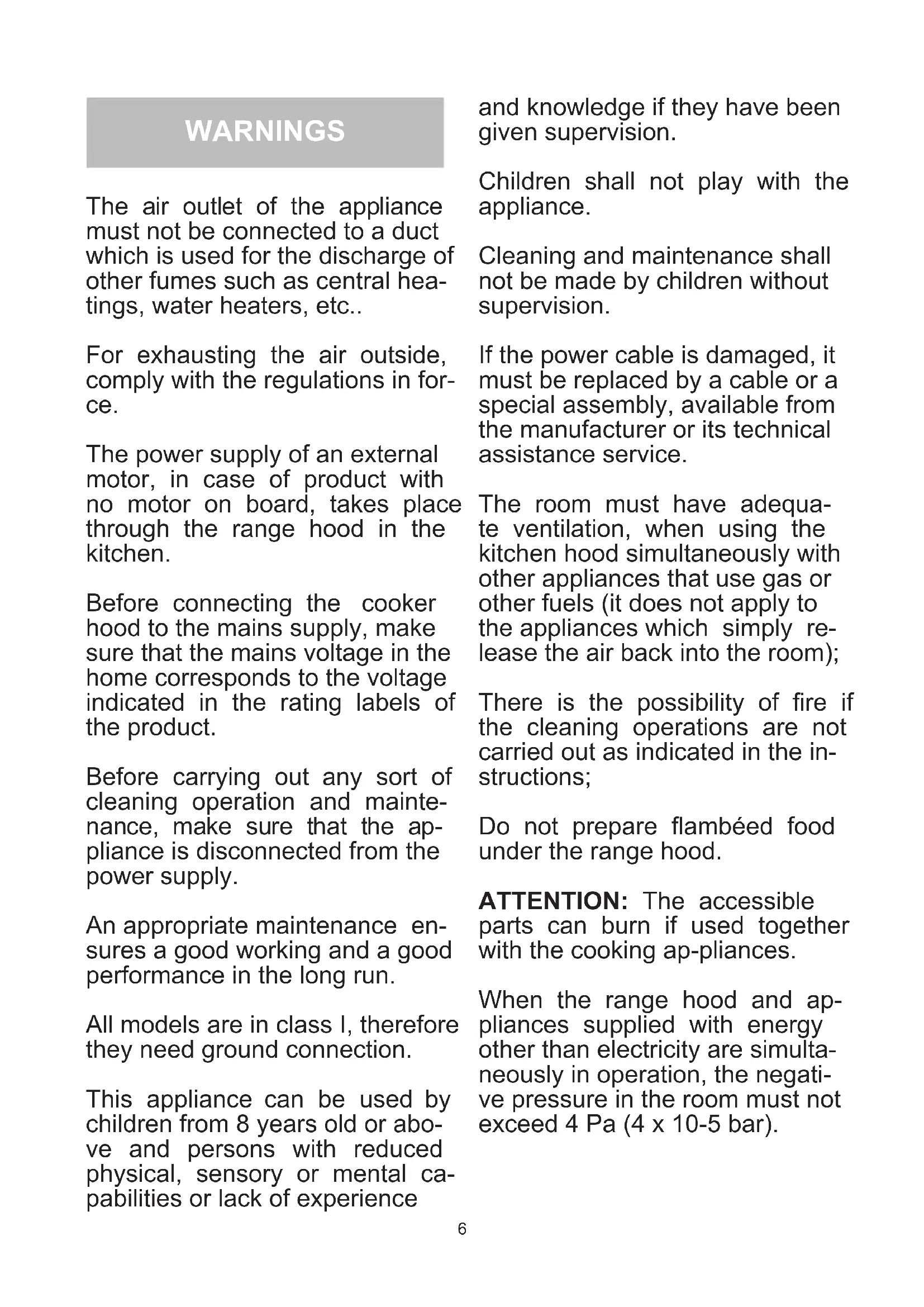
5and knowledge if they have been given supervision. Children shall not play with the appliance. Cleaning and maintenance shall not be made by children without supervision. If the power cable is damaged, it must be replaced by a cable or a special assembly, available from the manufacturer or its technical assistance service. The room must have adequa- te ventilation, when using the kitchen hood simultaneously with other appliances that use gas or other fuels (it does not apply to the appliances which simply re- lease the air back into the room); There is the possibility of re if the cleaning operations are not carried out as indicated in the in- structions; Do not prepare ambéed food under the range hood. ATTENTION: The accessible parts can burn if used together with the cooking ap-pliances. When the range hood and ap- pliances supplied with energy other than electricity are simulta- neously in operation, the negati- ve pressure in the room must not exceed 4 Pa (4 x 10⁻⁵ bar). WARNINGS The air outlet of the appliance must not be connected to a duct which is used for the discharge of other fumes such as central hea- tings, water heaters, etc.. For exhausting the air outside, comply with the regulations in for- ce. The power supply of an external motor, in case of product with no motor on board, takes place through the range hood in the kitchen. Before connecting the cooker hood to the mains supply, make sure that the mains voltage in the home corresponds to the voltage indicated in the rating labels of the product. Before carrying out any sort of cleaning operation and mainte- nance, make sure that the ap- pliance is disconnected from the power supply. An appropriate maintenance en- sures a good working and a good performance in the long run. All models are in class I, therefore they need ground connection. This appliance can be used by children from 8 years old or abo- ve and persons with reduced physical, sensory or mental ca- pabilities or lack of experience
INSTALLATION The minimum distance between the cooker surface and the lower part of the cooker hood must be 60cm in case of electric cooker and 65 cm in case of gas or mixed kitchens. If the installation instructions of the appliance for gas cooking indicate a higher distance, follow the specic instructions. Before proceeding with the installation, in order to avoid damaging the appliance, release the grea- se lters and the liquid waste tray. Metal grease lters can be removed by pushing the lter towards the back side of the hood and rotating it down, releasing it from its seat (g. 1). You can release the liquid waste tray by loose- ning the screws (g.2) and pulling out the metal tray. Essential requirements before installing the ap- pliance are the following ones: - Realization of a suitable opening on the bot- tom of the cabinet to proper install the applian- ce (g. 3). - Prepare the power supply. - Prepare an air exhausting hole and the spe- cic ducting system. Use an air exhausting duct, whose maximum length does not exceed 5 m. Limit the number of bends in the ducting system since every bend re- duces the suction efciency of 1 linear meter (e.g. if you use no.2 bends at 90°, the length of the ducting system must not exceed 3 meters). Use a 150 mm diameter duct for the whole length. The material of the duct must be compliant with the regulations in force. To install the appliance, adjust the position of the stop side-springs through the proper screws (g. 4), position the brackets 2-3 mm over the thickness of the cabinet bottom. Insert the built-in unit in the hole made in the cabinet until the stop click of the side- springs. Use the self-tapping screws 3,9x25 for stopping through the internal holes of the device (g. 5). Before making the electrical con- nections, check that: -the system ratings meet the ra- tings indicated on the identica- tion plate xed on the lower part of the worktop; -the system is tted with efcient ground wires in accordance with the laws and current standards. Grounding is mandatory by law. If the domestic appliance is not supplied with a cable and/or sui- table plug, use material suitable for the absorption value indica- ted on the identication plate and the operating temperature. If wishing to make a direct connec- tion to the mains, an omnipolar switch must be installed with a minimum 3 mm opening betwe- en the contacts and appropriate for the load indicated on the pla- te and in accordance with cur- rent standards (the yellow/green ground conductor must not be di- sconnected by a switch). When the appliance has been installed, the omnipolar switch must be ea- sily reachable.8 WORKING Push button L: Light switch on/off 0/1: Motor switch on (1st speed)/off 2: Motor switch 2nd speed 3: Motor switch 3rd speed 4: Motor switch 4th speed T: 10-minutes timer When the 4
speed of the motor is set, the rela- ting LED ashes. After 5 minutes the motor goes back to the 3
speed. By pushing the T button (timer), 10 minutes after setting it, the range hood is switched off. The function is highlighted by the led ashing ac- cording to the set speed. Press again the T but- ton to disactivate this function. The product automatically turns off after 4 hours of uninterrupted working, from the last function selected. After 30 hours working, the push button indicates the saturation of lter by lighting all buttons,for about 30 seconds. Press the timer button (T) to reset, while signa- ling. Push the appliance towards the bottom of the cabinet in order to make the frame of the ap- pliance perfectly adhere to the cabinet. Restore the liquid waste tray and the grease lters. Locking of the valve Warning! Before connecting the air outlet exible pipe to the motor, make sure that the non-return valve, placed on the air outlet of the motor, is free to rotate. Connect the ange of the hood to the exhaust hole through a suitable duct. Make the electri- cal connection through the power cable.
The products can be installed with the air out- let of the motor towards the back side of the product. If you want to use this option, you need to remove the motor support removing the screws (g. 6), pull out and rotate the sup- port, position it in its seat keeping the air out- let towards the rear side of the product (g. 7). Fix it with the screws previously removed. In case of external motor, connect the power cable of the motor to the terminal board in the black plastic box, identied through the con- nection label. ELECTRICAL CONNECTIONS If the unit is supplied with power cable with no plug, please refer to the schema below. POWER SUPPLY SHOWN IN THE RATING LABEL 3X0.75mm2An accurate maintenance guarantees a good functioning and a long-lasting performance. Pay attention to the grease lters. The lter can be removed by pushing it towards the back part of the hood and rotating the lter downwards, releasing it from its seat (g. 1). To insert the lter, just perform the opposite opera- tion. The grease lter can be washed by hand or in the dishwasher. After releasing the steel lters, hold the liquid wa- ste tray in one hand and, with the other hand, lo- osen the knobs as indicated in g. 2, let the liquid waste tray swipe down taking care not to pour any liquids. For cleaning, use ONLY a damp cloth with neutral liquid detergents. DO NOT USE TOOLS OR INSTRUMENTS FOR CLEANING! Avoid using abrasive products. DO NOT USE ALCOHOL. The replacement of the power cable must be car- ried out by authorized staff. Replacement of the LED bar: By using an appropriate tool, remove the LED bar from its seat (Fig. 8), disconnect it elec- tronically through the appropriate connec- tor, then replace it with a LED bar having the same features. MAINTENANCE 9INDICE Avvertenze Installazione Funzionamento Manutenzione
Для сброса нажмите кнопку таймера (T) во время подачи сигнала.50 The symbol on the product or on its packaging indicates that this product may not be treated as household waste. Instead it shall be handed over to the applicable collec- tion point for the recycling of electrical and electronic equipment. By ensuring this pro- duct is disposed of correctly, you will help prevent potential negative consequences for the environment and human health, which could otherwise be caused by inappropriate waste handling of this product. For more detailed information about recycling of this pro- duct, please contact your local city ofce, your household waste disposal service or the shop where you purchased the product. This appliance is marked according to the Eu- ropean directive 2012/19/EC on waste electrical and electronic equipment (WEEE).