
ULY12EAW - Air-conditioner SHARP - Free user manual and instructions
Find the device manual for free ULY12EAW SHARP in PDF.
| Product type | Mobile monobloc air conditioner |
| Brand | Sharp |
| Model | ULY12EAW |
| Dimensions (W x H x D) | 393 x 425 x 804 mm |
| Net weight | 35.0 kg |
| Power supply | 220-240 V ~ 50 Hz |
| Refrigerant | R290 (flammable) |
| Cooling capacity | 3520 W |
| Heating capacity | 3100 W |
| Energy class (cooling / heating) | A / A+ |
| Power consumption (cooling) | 1345 W |
| Power consumption (heating) | 1190 W |
| Standby consumption | 0.5 W |
| Airflow (high / medium / low) | 385 / 355 / 325 m³/h |
| Noise level (high / medium / low) | 65 / 64 / 62 dB(A) |
| Operating temperature range | 16 °C to 30 °C |
| Recommended room area | 16 - 23 m² |
| Operating modes | Cool, Dry, Fan, Heat |
| Special functions | 24h timer, oscillation, remote control, sleep |
| Supplied accessories | Remote control, batteries, exhaust hose, seal, rear bracket, drain connector, cord hooks, screws |
| Filter cleaning | Every 3 months (more often in dusty environment) |
Frequently Asked Questions - ULY12EAW SHARP
User questions about ULY12EAW SHARP
0 question about this device. Answer the ones you know or ask your own.
Ask a new question about this device
Download the instructions for your Air-conditioner in PDF format for free! Find your manual ULY12EAW - SHARP and take your electronic device back in hand. On this page are published all the documents necessary for the use of your device. ULY12EAW by SHARP.
USER MANUAL ULY12EAW SHARP
natural_image
Line drawing of a rectangular electronic device with control panel and ventilation slots (no text or symbols)User manual
UL-C10EA-W, UL-C12EA-W, UL-Y12EA-W
Portable air conditioner
ENESITPTDEFRPL
□ □
□ □
Product images are for illustration purposes only. Actual product may vary.
* - only for model | nur für modell | solo para modelo | uniquement pour le modèle | solo per modello | tylko dla modelu | apenas para modelo UL-Y12EA-W
Sharp will not be held responsible for personal injury or loss to property for the following:
- Any damage to the product caused by neglect, poor maintenance, incorrect handling or misuse;
- Any altering, changing or use of the product with any other equipment which is not detailed in this User Manual;
- If, after verification, damage or gas leakage has been caused by corrosive gas;
- If, after verification, damage or gas leakage has been caused by incorrect transportation of the product;
- Operate, repair, maintain the unit without abiding to the instructions in this User Manual or related regulations;
- After verification, the problem or dispute is caused by the quality specification or performance of parts and components that have been produced by other manufacturers;
- If any damage has been caused by natural calamities, bad using environment or force majeure.
- When refrigerant leaks or requires discharge during installation, maintenance, should carried out by certified professionals or otherwise in compliance with local laws and regulations.
- This appliance is not intended for use by persons (including children) with reduced physical, sensory or mental capabilities or lack of experience and knowledge, unless they have been given supervision or instruction concerning use of the appliance by a person responsible for their safety.
- Children should be supervised to ensure that they do not play with the appliance.
The Refrigerant
- To realize the function of the air conditioner unit, a special refrigerant circulates in the system. The used refrigerant is fluoride R290, which has been specially cleaned before installation to the refrigeration system. The refrigerant is flammable and inodorous. Furthermore, it can lead to explosion under certain conditions.
- Compared to common refrigerants, R290 is a nonpolluting refrigerant which does not harm the ozonosphere. The influence upon the greenhouse effect is also lower. R290 has got very good thermodynamic features which leads to a really high energy efficiency. The units therefore need a less filling.
Warning:
- Appliance filled with flammable gas R290.
- Appliance is recommended to be installed, operated and stored in a room with a floor area larger than 11m^2 .
- The appliance is not to be stored in a room with continuously operating ignition sources. (for example: open flames, an operating gas appliance or an operating electric heater).
- The appliance shall be stored in a well-ventilated area where the room size corresponds to the room area as specified for operation.
- The appliance shall be stored so as to prevent mechanical damage from occurring.
- Ducts connected to an appliance shall not contain an ignition source.
- Keep any required ventilation openings clear of obstruction.
- Do not pierce or burn.
- Be aware that refrigerants may not contain an odour.
- Do not use means to accelerate the defrosting process or to clean, other than those recommended by the manufacturer.
- Servicing shall be performed only as recommended by the manufacturer.
- Should repair be necessary, contact your nearest authorized Service Centre. Any repairs carried out by unqualified personnel may be
dangerous, not covered under warrant and not supported by the manufacturer.
- Compliance with national gas regulations have to be observed.
Important safety instructions
WARNING
Risk of Fire / Flammable Materials
natural_image
Warning sign depicting a flame inside a triangle (no text or symbols)Please, read these safety instructions and respect the following warnings before the appliance is operated:

The lightning flash with arrowhead symbol, within an equilateral triangle, is intended to alert the user to the presence of uninsulated "dangerous voltage" within the product's enclosure that may be of sufficient magnitude as to constitute a risk of electric shock to persons.

The exclamation point within an equilateral triangle is intended to alert the user to the presence of important operating and maintenance (servicing) instructions in the literature accompanying the appliance.

This symbol means that the product should be disposed of in an environmentally friendly manner and not with general household waste.

Appliance filled with flammable gas R290.

Before using and installing the appliance, read the installation manual first.

"There are Specialists notes contained at the end of this User Manual which relate to the servicing of this product. These are only to be used by qualified persons."

Before using the appliance, read the owner's manual first.

AC voltage
In order to prevent fi re always keep candles and other open fl ames away from this product.

Warning:
- This appliance can be used by children aged from 8 years and above and persons with reduced physical, sensory or mental capabilities or lack of experience and knowledge if they have been given supervision or instruct ion concerning use of the appliance in a safe way and understand the hazards involved.
- Do not allow children to play with the appliance.
- Cleaning and user maintenance must not be carried out by children without supervision.
- Before operation, please confirm that the mains supply power specification complies with that on rating plate (this is located on the side of the product).
- Before cleaning or maintaining the air conditioner, please turn off air conditioner and disconnect the power plug.
- Do not damage or alter the powercord arbitrarily. It should not be twisted, extended, bundled up or placed near hot places. Do not place heavy items on the power cord or place the cord in the gap between objects.
- Do not pull or drag the power cord to pull out the power plug or move the air conditioner.
- Do not insert or pull out the power plug with wet hands.
- Ensure that the appliance is grounded. Make sure the grounding is reliable. If in doubt about the grounding of the product, seek professional advice.
- If the supply cord is damaged, it must be brought to the dealer for repair or replacement to prevent any hazards occurring.
- In case of an exception (e.g., burn t smell), please turn off the product immediately. Remove its power plug and contact the dealer for repair.
- When the appliance is not in use or undergoing maintenance, please turn off the power supply and pull out the power plug to avoid damaging the unit.
- Do not splash or pour water on this product as it may cause a short circuit or damage to air conditioner.
- Do not use the drainage hose below 0^ . A frozen drainage hose will cause water to leak from the appliance.
- Do not operate heating equipment around the air conditioner.
- Do not operate the unit in the bathroom or laundry room.
- Keep the appliance far way from sources of fire, flammable and explosive items.
- Children and disabled people are not allowed to use the portable room air conditioner without supervision.
- Keep children from playing or climbing on the air conditioner.
- Do not put or hang dripping objects above the air conditioner.
- Do not repair or disassemble the air conditioner by yourself.
- Do not insert any objects into the air conditioner.
- Make sure there are no foreign substances in air duct. Should any foreign substances get into the air duct, please contact the dealer to prevent any hazards occurring.
- Do not use an extension cord.
Operation Environment:
- The air conditioner must be operated within the temperature range of 16^ to 35^ :
• The appliance is for indoor use only. - The appliance must be positioned so that the plug is accessible.
-
This air conditioner can only be used in domestic environments, it is not to be used in commercial areas.
-
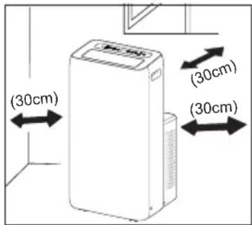
Allow a gap of at least 30 cm around the appliance and ensure floor surface is smooth and flat.
- Do not operate the air conditioner at humid environment.
- Keep the air inlet and outlet clean and unobstructed.
- During operation, close doors and windows to improve cooling effect.
- Locate the appliance on a smooth and flat surface to avoid excessive noise and vibration.
- This air conditioner is equipped with castors. Castors should slide at smooth and flat ground.
- Do not install near stairs or steps.
- Prohibit inclining or turning over the air conditioner. If there's abnormality, please disconnect power immediately and contact the dealer to prevent any hazards occurring.
- Avoid direct sunshine.
Disposal of this equipment and batteries
- IF YOU WISH TO DISPOSE OF THIS EQUIPMENT OR ITS BATTERIES, DO NOT USE THE ORDINARY WASTE BIN, AND DO NOT PUT THEM INTO A FIREPLACE!
- Used electrical and electronic equipment and batteries should always be collected and treated SEPARATELY in accordance with local law.
- Separate collection promotes an environment friendly treatment, recycling of materials, and minimizing final disposal of waste. IMPROPER DISPOSAL can be harmful to human health and the environment due to certain substances! Take USED EQUIPMENT to a local, usually municipal, collection facility, where available.
- Remove USED BATTERIES from equipment, and take them to a battery collection facility; usually a place where new batteries are sold.
- If in doubt about disposal, contact your local authorities or dealer and ask for the correct method of disposal.
• ONLY FOR USERS IN THE EUROPEAN UNION, AND SOME OTHER COUNTRIES; FOR INSTANCE NORWAY AND SWITZERLAND: - Your participation in separate collection is requested by law.
- The symbol shown above appears on electrical and electronic equipment and batteries (or the packaging) to remind users of this. If 'Hg' or 'Pb' appears below the symbol, this means that the battery contains traces of mercury (Hg) or lead (Pb), respectively.
- Users from PRIVATE HOUSEHOLDS are requested to use existing return facilities for used equipment and batteries. Batteries are collected at points of sale. Return is free of charge.
- If the equipment has been used for BUSINESS PURPOSES, please contact your SHARP dealer who will inform you about take back. You might be charged for the costs arising from take back. Small equipment (and small quantities) might be taken back by your local collection facility. For Spain: Please contact the established collection system or your local authority for take back of your used products.
- Most of the EU countries regulate the disposal of batteries by law.
Recycling symbol appears on electrical equipment, packaging and batteries to remind users to dispose these items correctly. Users are requested to use existing return facilities for used equipment and batteries. Contact your retailer or local authorities for more information.
CE and UKCA statement:
- The full text of the EU declaration of conformity is available by following the link www.sharpconsumer.com and then entering download section of your model and choosing "CE Statements".


www.sharpconsumer.com/contact/

www.sharpconsumer.com/support/

www.sharpconsumer.com/documents-of-conformity/
For service, please refer to www.sharpconsumer.com/contact/, for your warranty rights go to www.sharpconsumer.com/support/ or contact the retailer where you purchased your product.
Declarations of conformity are available from www.sharpconsumer.com/documents-of-conformity/
Contents of the Box
NOTE
- Check if the accessories are available before installation.
Refer to the pictures 📌 6 on page 2.
- Joint A (× 1)
- Rear Clip (× 1)
- Heat Discharge Pipe (× 1)
- Drain Connector (× 1)
- Power Cord Hooks (× 2)
- Screws (× 2)
- Remote Control (× 1)
- AAA 1.5 V R03 batteries (× 2)
- User manual (× 1)
- Warranty card (× 1)
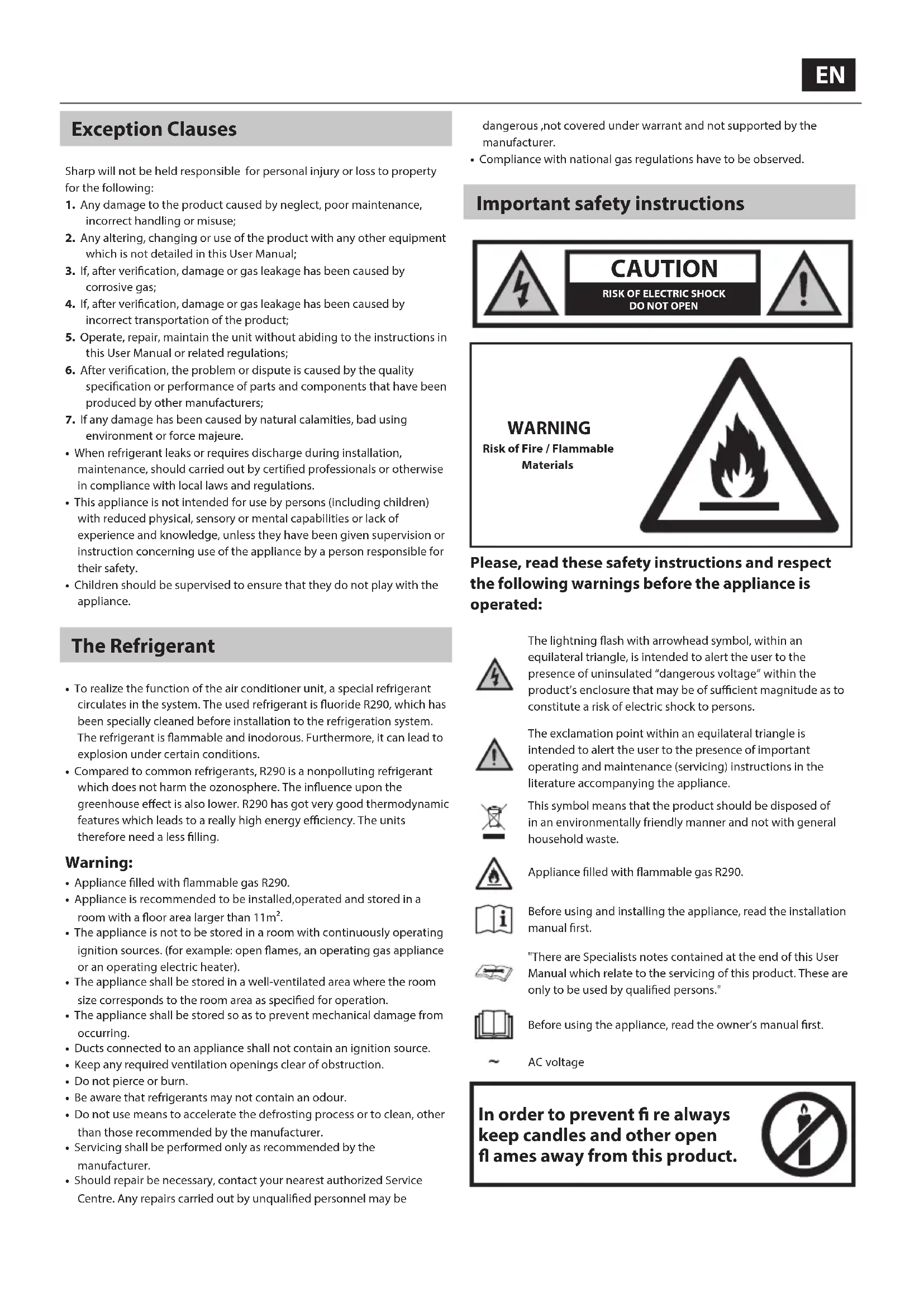
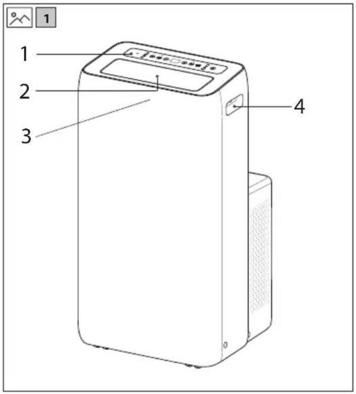
Part Names
Refer to the pictures 1 and 2 on page 1.
- Controller panel
- Guide louver
- Signal receiver
- Handles
- Filter
- Air inlet
- Middle drainage port
- Power cord
- Power cord hooks
- Plug storage space
- Bottom drainage port
- Castors
NOTICE: Some installation accessories can't be discarded.
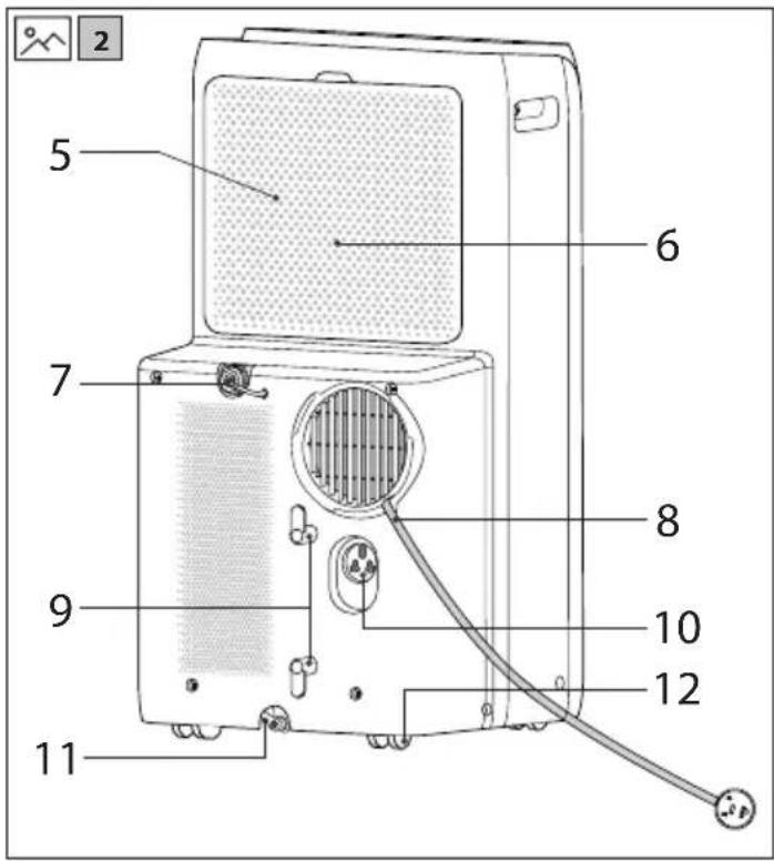
Control Panel
Refer to the pictures 3 on page 1.
- Fan speed indicator
- Fan button
- Swing button
- Swing indicator
-
- / - button
- Display panel
- Timer indicator
- Timer button
- Mode button
- Cool mode indicator
- Dry mode indicator
- Fan mode indicator
- Heat mode indicator (UL-Y12EA-W Cool and Heat model only)
- ON/OFF button
NOTE:
- After connecting the power, the air conditioner will emit a sound. After this, you can operate the air conditioner by the control panel.
- When the appliance is turned on, it will emit a sound each time a button is pressed. When a button is pressed, the associated light will turn on or off.
- When the appliance is turned off, the display will also be off. When turned on, the display panel on control panel will display set temperature under Cooling mode and Heating mode (Cool and Heat model only).
Operation of Control Panel
ON/OFF button
Pressing this button turns the air conditioner on and off.
+ / - button
Under cooling or heating mode, press "+" or "-" button to increase or decrease set temperature by 1°C. Set temperature range is 16°C to 30°C. When in the auto, dry or fan mode, these buttons will not operate.
Fan button
Press this button and the fan speed will change as:
low speed >> medium speed >> high speed >> auto fan
Mode button
Press this button and the mode will change as:
COOL >> DRY >> FAN >> HEAT (Cool and Heat model only)
COOL: Under this mode, cool mode indicator will be on.
Display panel displays set temperature.
Temperature setting range is 16^ C \~ 30^ C.
DRY: Under this mode, dry mode indicator will be on.
Display panel won't display.
FAN: Under this mode, only the fan will work. Fan mode indicator will go on. Display panel won't display.
HEAT (Cool and Heat model only): Under this mode, heating mode indicator will go on. Display panel displays set temperature. Temperature setting range is 16^ C \~ 30^ C.
Timer button
When setting the timer in the off mode, it will work as an ON timer function. When setting the timer in the on mode, the timer will work as an OFF timer. Note that the ON timer and OFF timer cannot be set together. Press the timer button to enter the timer set mode. When in the timer mode, use the - and + buttons to select the time in 0.5 intervals. When the display shows 10 hours, the + and - buttons will set in 1 hour intervals. After setting duration time, press timer button again to confirm the setting When ON timer is set, the unit will start operating when the time set has elapsed. When OFF timer is set, after setting the timer, the timer display will be replaced with the temperature after five seconds. To cancel the timer, press the timer button again.
Swing
Press this button, horizontal louver of air conditioner will swing up and down automatically. Single press it to switchover between on and off.
Remote control
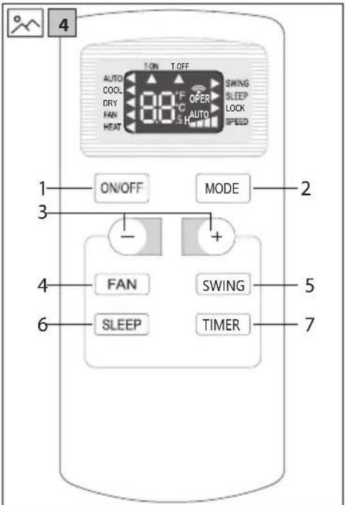
Remote control buttons
Refer to the pictures 4 on page 1.
-
ON/OFF
-
MODE
-
+/-
-
FAN
-
SWING
-
SLEEP
-
TIMER
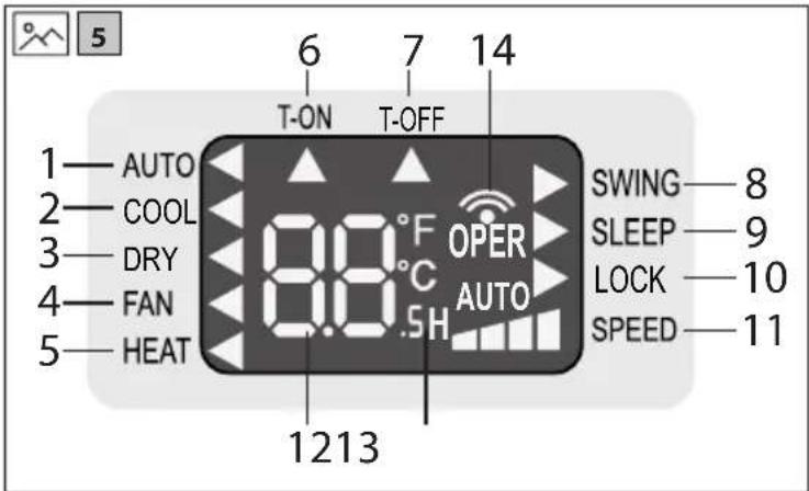
Remote control display
Refer to the pictures 5 on page 1.
-
AUTO - Auto mode
-
COOL - Cool mode
-
DRY - Dry mode
-
FAN - Fan mode
-
HEAT - Heat mode (Cool and Heat models only)
-
T-ON - Timer on
-
T-OFF - Timer off
-
SWING – Swing operation
-
SLEEP – Sleep operation
-
LOCK - Lock
-
SPEED - Set fan speed
-
Set temperature
-
Set time
-
Send signal
Remote control functions
NOTE:
- The remote control may have more functionality than your air conditioner has. If any additional buttons are pressed, they will have no affect on the operation of the unit.
- When power is connected (stand by condition), you can operate the air conditioner through the remote control.
- When unit is on, each time you press the button on remote control, the signal icon "💡" on the display of remote control will blink once. If the air conditioner emits a sound, it means the signal has been sent.
- When unit is off, set temperature will be displayed on the remote control (If the light of indoor unit display is turned on, the corresponding icon will be displayed). When unit is on, the icons of the ongoing functions will be displayed on the remote control.
ON/OFF button
Press this button to turn unit ON/OFF.
MODE button
Pressing this button once can select your required mode as shown below. (the corresponding icon "◀" will be lit up after the mode is selected):
AUTO >> COOL >> DRY >> FAN >> HEAT (Cool and Heat model only)
- When selecting AUTO, air conditioner will operate automatically according to ambient temperature. Set temperature can't be adjusted and won't be displayed either. Press FAN button to adjust fan speed.
- When selecting COOL, air conditioner will operate under cooling mode. Then press + or - button to adjust set temperature. Press FAN button to adjust fan speed.
- When selecting DRY, air conditioner will operate at low fan speed under dry mode. In dry mode, fan speed can't be adjusted.
- When selecting FAN, air conditioner will operate in fan mode only. Then press FAN button to adjust fan speed.
- When selecting HEAT, air conditioner will operate under heating mode. Then press + or - button to adjust set temperature. Press FAN button to adjust fan speed. (Cooling only unit can't receive heating mode signal. If
HEAT is selected by remote control, pressing ON/OFF button can't turn on the air conditioner.)
+/- button
- Pressing + or - button once will increase or decrease set temperature by 1°C. Hold + or - button for 2 seconds, set temperature on remote controller will change quickly. Release the button after your required set temperature is reached. (Temperature can't be adjusted under auto mode)
- When setting Timer On or Timer Off, press + or - button to adjust the time. (See TIMER Button for setting details)
FAN button
- Pressing this button can select fan speed as: AUTO, SPEED 1 ( ), SPEED 2 ( ), SPEED 3 ( ), SPEED 4 ( ).
NOTE:
- Under Auto speed, air conditioner will select proper fan speed automatically according to ambient temperature. - Fan speed can't be adjusted under dry mode.
SWING button
Press this button to turn on up & down air swing.
SLEEP button
- Press sleep button to enter into sleep mode. If the controller operates at cooling mode, after sleep mode is started up, preset temperature will increase by 1 °C within 1 hour; preset temperature will increase by 2 °C within 2 hours and then the unit will operate at this temperature until turned off.
- Press sleep button to enter into sleep mode. If the controller operates at heating mode (Cooling and Heating models only), after sleep mode is started up, preset temperature will decrease by 1 °C within 1 hour; preset temperature will decrease by 2 °C within 2 hours and then the unit will operate at this temperature until turned off.
- Sleep function is only available for cooling mode and heating mode. SLEEP function can be set together with OFF timer.
TIMER button
- When unit is on, press this button to set Timer Off. T-OFF and H icon will blink. Within 5s, press + or - button to adjust the time for Timer Off. Pressing + or - button once will increase or decrease the time by 0.5 hours. Hold + or - button for 2 seconds, time will change quickly. Release the button after your required set time is reached. Then press TIMER button to confirm it. T-OFF and H icon will stop blinking.
- When unit is off, press this button to set Timer On. T-ON and H icon will be blinking. Within 5 seconds, press + or - button to adjust the time for Timer On. Pressing + or - button once will increase or decrease the time by 0.5 hours. Hold + or - button for 2 seconds, time will change quickly. Release the button after your required set time is reached. Then press TIMER button to confirm it. T-ON and H icon will stop blinking.
- Canceling the timer function: If Timer function is set up, press TIMER button once to review the remaining time. Within 5 seconds, press TIMER button again to cancel this function.
- ON timer and OFF timer cannot be set together.
NOTE:
- Range of time setting is: 0.5\~24 hours.
- The interval between two motions can't exceed 5 seconds, otherwise the remote control will exit setting status.
Functions by Combination Buttons
Child lock function
Press "+" and "-" buttons simultaneously can turn on or turn off child lock function. When child lock function is started up, child lock indicator on remote controller is ON. If you operate the remote control, remote control won't send signal.
This function works only for remote controller, the buttons on the unit itself can not be locked.
Temperature display switchover function
Under OFF status, press "-" button and "MODE" button simultaneously can switch between °C and °F.
Light function
You can turn off or turn on the light of the unit's control panel. Under switch-on or switch-off status, point the remote control to the unit's signal receiver and you may hold "+" and "FAN" buttons simultaneously for 3 seconds to set the light on or off.
Installation of batteries
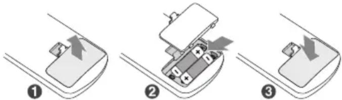
- Press and slide the back cover to open the battery compartment of the remote control.
- Insert two AAA (1,5 V) size batteries (included). Make sure the (+) and (−) ends of the batteries match the (+) and (−) ends indicated in the battery compartment.
- Close the battery compartment cover.
NOTE:
- During operation, point the remote control signal sender at the receiving window on indoor unit.
– The distance between signal sender and receiving window should be no more than 8 meters, and there should be no obstacles between them.
– Signal may be interfered easily in the room where there is fluorescent lighting or wireless telephone; in these situations, move the remote control closer to the appliance for reliable operation. - Replace new batteries of the same model when replacement is required.
- If you will not be using the unit for a long time, remove the batteries from the remote control.
- If the display on remote control is fuzzy or there's no display, please replace batteries.
Care and Maintenance
WARNING!
- Before cleaning the air conditioner, please turn off the unit and disconnect power. This will ensure that the risk of an electric shock is eliminated.
- Do not wash air conditioner with water. This will ensure that the risk of an electric shock is eliminated.
- Do not use volatile liquid (such as thinner or gas) to clean the air conditioner. Otherwise, it may damage the surface.
- Do not use liquid or corrosive detergent clean the appliance and do not splash water or other liquid onto it, otherwise, it may damage the plastic components, or even cause electric shock.
Clean outer case and grille
Clean outer case:
If there's dust on the surface of outer case, please use soft cloth to wipe it. If the outer case is very dirty (such as grease), please use neutral detergent to wipe it.
Clean grille:
To clean the grille itself, use a soft brush.
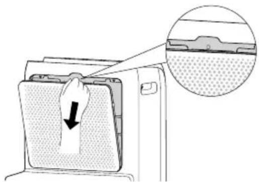
Clean filter
(Do not touch the fins to prevent injury.)
- Remove the filter
Press the clasp as shown in the figure, and then remove the filter;
natural_image
Diagram showing a hand pressing down on a device with a magnified inset highlighting the interior structure (no text or symbols)2. Clean filter
Use a vacuum cleaner or water to clean the filter. If the filter is very dirty (such as grease), use warm water 40^ C with neutral detergent dissolved to clean and then put at shady place to dry it.
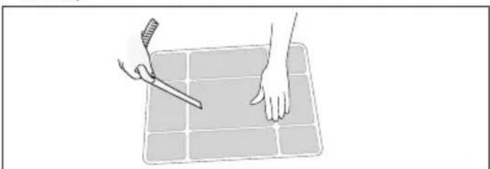
3. Install filter
After the filter is cleaned and dried, ensure that it is reinstalled correctly.
natural_image
Illustration of hands using a tool to cut or mark a grid on a flat surface (no text or symbols)NOTE
- The filter should be cleaned about once every three months. If there is a large amount of dust in the operation environment, you can increase cleaning frequency.
- Do not dry the filter with a direct heat source or hair drier. Otherwise, it may be deformed or catch fire.
Clean heat discharge pipe
Remove the heat discharge pipe from air conditioner, clean and dry it, and then reinstall it. (For the method of installation, please refer to the instruction for "Installing heat discharge pipe".)
Checking before use-season
- Check whether air inlets and air outlets are blocked.
- Check whether plug and socket are in good condition.
- Check whether filter is clean.
- Check whether batteries are installed in remote control.
- Check whether joint, window bracket and heat discharge pipe are installed firmly.
- Check whether heat discharge pipe is damaged.
Checking after use-season
- Disconnect power supply.
- Clean filter and outer case.
- Remove dust and sundries on the air conditioner.
- Eliminate accumulated water in chassis (refer to the section of "Removing collected water" for details).
- Check whether window bracket is damaged or not.
- If yes, please contact the dealer.
Long-time storage
If you don't use the air conditioner for a long time, please maintain it by following steps for good performance:
- Make sure that there is no accumulated water in chassis and the heat discharge pipe is disassembled.
- Pull out the plug and wrap the power cord.
- Clean the air conditioner and pack it well to prevent dust.
Notice for recovery
- Some of the packing items are recyclable materials. Please deal with them through your local recycling provider.
- If you want to dispose the air conditioner, please contact local authority or consultant service center for the correct disposal method.
Troubleshooting
Before calling for service, please review the troubleshooting list below, since the problem may not be a main unit malfunction.
Air conditioner can't operate
Cause / Action
• Power failure? / Wait after power recovery.
• Is plug loose? / Reinsert the plug.
- Whether the air switch is tripped off or fuse is burnt? / Ask professional person to replace air switch or fuse.
- Is there malfunction for the circuit? / Ask professional person to replace circuit.
- Whether the unit is restarted up after stopping immediately? / Wait for 3 minutes, and then turn on the unit again.
Water flowing noise
Cause / Action
- Whether the unit is turned on or turned off just now? / There's flowing sound of refrigerant inside the air conditioner which is the normal phenomenon.
Poor cooling (heating)
Cause / Action
- Is the power too low? / Wait after voltage is resumed.
- Whether the air filter is too dirty? / Clean the air filter.
- Has the correct temperature been set? / Adjust the temperature.
- Whether door and window are closed? / Close door and window.
Air conditioner can't receive signal from remote control or remote control is not sensible.
Cause / Action
- Whether the unit is interfered seriously (such as static pressure, unstable voltage)? / Please pull out the plug. Insert the plug after about 3 minutes, and then turn on the unit.
- Whether remote controller is within the receiving range? / The receiving range of remote controller is 8 meters. Do not exceed this range.
- Whether it's blocked by obstacles? / Remove the obstacles.
- Is sensitivity of remote controller low? / Check the batteries of remote controller. If the power is low, please replace the batteries.
- Whether there's fluorescence lamp in the room? / Move the remote controller close to air conditioner. Turn off the fluorescence lamp and try it again.
Cracking noise
Cause / Action
- Whether the unit is turned on or turned off just now? / Heat expansion or shrinkage for the panel due to change of temperature, which cause friction sound.
There's abnormal sound during operation
Cause / Action
- Whether the unit is interfered by thunder, radio, etc? / Disconnect power, put through the power again, and then turn on the unit again.
Odors
Cause / Action
- There's off-flavour source in the room, such as furniture, cigarette etc. / Eliminate the off-flavour source. Clean the filter.
No air blown out from air conditioner
Cause / Action
- Whether air outlet or air inlet is blocked? / Eliminate the obstacles.
- Under heating mode, whether indoor temperature increase set temperature? (Cool and Heat model only) / The unit will stop blowing fan after reaching set temperature.
- Whether heating mode is started up just now? (Cool&Heat model only) / In order to prevent cold air, air conditioner will delay for a while to be started up, which is the normal phenomenon.
- Whether evaporator is defrosted? (confirm this by pulling out the filter) / It's the normal phenomenon. Air conditioner is defrosting. After defrosting is finished, it will resume operation.
Set temperature can't be adjusted.
Cause / Action
- Whether the unit operates under auto mode? / Temperature can't be adjusted under auto mode.
- Whether the required temperature exceeds the temperature setting range? / Temperature setting range: 16°C to 30°C
- Whether the unit is turned on or turned off just now? / There's flowing sound of refrigerant inside the air conditioner, which is the normal phenomenon.
Error codes
It is possible for error codes to appear in the display. If they do, take the appropriate action as shown below.
F1, F2, F4, F0:
Please contact qualified professionals for service.
E8, H3
- Check if the unit is under high-temperature and high-humidity environment; if ambient temperature is too high, power off the unit and then energize it for operation after the ambient temperature drops to 35^ C below.
- Check if the evaporator and condenser are blocked by some objects; if yes, take away the objects, power off the unit and then energize it for operation.
- If the malfunction still occur, please contact service center.
H8
- Drain the water inside chassis.
- If "H8" still exist, please contact the dealer to maintain the unit.
WARNING!
- If any of the phenomenon listed below occur, turn off the air conditioner and disconnect the power immediately, and then contact the dealer immediately.
– Power cord is overheating or damaged - Abnormal sound during operation
- Odors
- Water leakage
- Do not repair or refit the air conditioner by yourself.
- If operate the air conditioner under abnormal condition, it may cause malfunction, electric shock or fire hazard.
Installation Precautions
WARNING!
- Observe all governing codes and ordinances.
- Do not use damaged or non-standard power cord.
- Be caution during installation and maintenance. Prohibit incorrect operation to prevent electric shock, casualty and other accidents.
Selection of installation location
Basic requirement
Installing the unit in the following places may cause malfunction. If it is unavoidable, please consult your dealer for advice.
- Locations with high temperature heat sources, vapors, flammable or explosive gas, or volatile objects spread in the air.
- Anywhere which has high-frequency devices installed (such as welding machine, medical equipment).
- Near to a coastal area.
- Anywhere which has oil or fumes in the air.
- Near to sulfureted gas.
- Other places with special circumstances.
- Do not install on unstable or motive base structure (such as truck) or in a corrosive environment (such as chemical factory).
Requirement of air conditioner
- Air inlet should be far away from obstacles and do not put any objects near to the air outlet. Otherwise, it will affect the performance of heat discharge pipe.
- Select a location where the noise and outflow air emitted by the unit will not affect your local neighborhood.
- Please try your best to keep far away from fluorescent lamps.
- Do not install this appliance in a laundry room.
- Do not install near stairs or steps.
Requirements for electric connection
Safety precaution
- You must follow the electric safety regulations when installing the unit.
- Follow your local safety regulations and ensure that the correct electrical supply is used.
- If the supply cord is damaged, it must be replaced by the manufacturer, its service agent or similarly qualified persons in order to avoid a hazard.
- Properly connect the live wire, neutral wire and grounding wire of power socket.
- Be sure to turn off the power supply before proceeding any work related to electricity and safety.
- Do not connect the power before finishing installation.
- The air conditioner is a class 1 electric appliance and must be correctly grounded. Please make sure it is always grounded effectively, otherwise it may cause electric shock.
- The yellow-green wire or green wire in air conditioner is grounding wire, which can't be used for other purposes.
- The grounding resistance should comply with your local electrical safety regulations.
- The appliance shall be installed in accordance with your countries wiring regulations.
- To be in compliance with IEC 61000-3-11, impedance value of power-supply system connected to product must be less than or equal to the allowable maximum value of |Zsys| in the following sheet:
| models max |Zsys| unit:ohm | |
| UL-C10EA-W | 0.13 |
| UL-C12EA-W | |
| UL-Y12EA-W | |
| UL-C10UA-W |
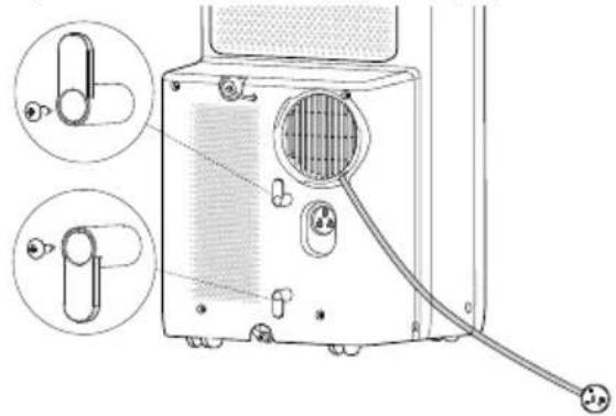
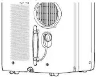
Install Power Cord Hooks
Assemble the power cord hooks at the back of the unit with screws (the direction of power cord hooks is as shown in following figure).
natural_image
Diagram of a portable air conditioner unit with attached cable and two circular components (no text or symbols)Wind the power cord around the power cord hooks.
natural_image
Technical line drawing of a device rear panel with ventilation grille and mechanical components (no text or symbols)Drain Water
- To reach the maximum performance, it is not recommended to drain water, during Cooling mode.
- It is recommended to use the middle drainage port to drain water, during Dry mode.
- It is recommended to use the middle drainage port to drain water, during Heating mode.
- To drain water from the bottom drainage port when th edisplay shows H8.
Drainage method
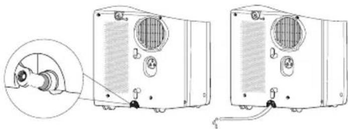
1 Drain water from the bottom drainage port.
- Turn off the unit and pull out the plug from the socket.
- Place a water container under the bottom drainage port, or move the machine to a place where it can drain.
- Remove the rubber plug of the bottom drainage port to drain water.
• After draining, insert the rubber plug. - Press ON/OFF button to restart.
natural_image
Diagram showing two views of a portable air conditioner unit with a close-up inset view of the front panel (no text or symbols present)2 Drain water from the middle drainage port.
NOTE
- Water can be automatically emptied into a floor drain by attaching 13 mm inner diameter hose (not included).
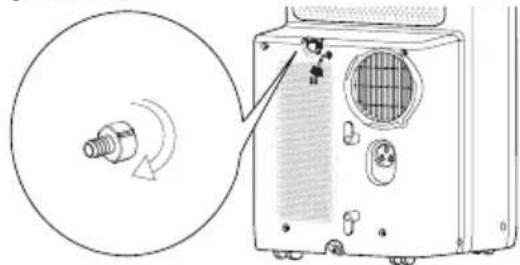
- Remove the continuous drain cap by turning it counter clockwise then remove the rubber stopper from the spout.
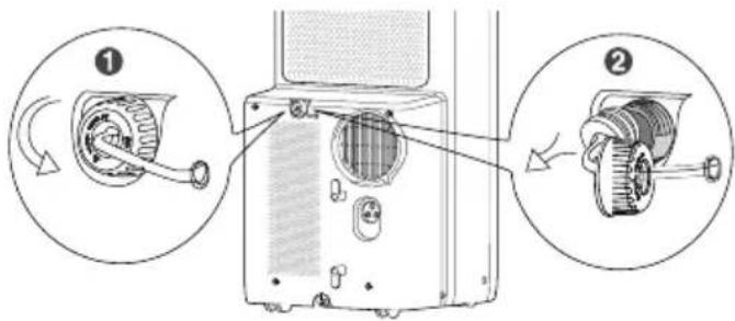
- Screw the drain connector to (included in the package) the spout by turning clockwise.
natural_image
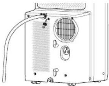
Diagram of a device showing internal components with a magnified view of a mechanical component (no text or symbols present)- Insert a 13 mm inner diameter hose (not included) onto drain connector.
natural_image
Line drawing of a portable air conditioner unit with ventilation duct, buttons, and fan (no text or symbols)ATTENTION:
- When using continuous drainage option from the middle hole, place the unit on a level surface and make sure drainage hose is clear of any obstructions and is directed downward. Placing the unit on an uneven surface or improper hose installation may result in water filling up the chassis and causing the unit to shut off. Empty water in the chassis if shut off occurs, then check the unit location and hose for proper setup.
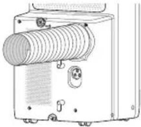
Installing Heat Discharge Pipe
Install heat discharge pipe
- Rotate joint A and Rear clip clockwise into the two ends of heat discharge pipe.
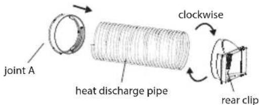
- Insert joint A of heat discharge pipe into the groove until you hear a clicking sound.
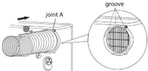
- Lead the heat discharge pipe outdoors.
natural_image
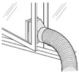
Technical line drawing of a pipe connection with support structure (no text or symbols)Note on installing heat discharge pipe
In order to improve cooling efficiency, the heat discharge pipe should be as short as possible and flat without curve to ensure smooth heat discharge. The discharge pipe is suggested to be installed according to below figure.
natural_image
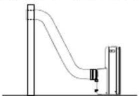
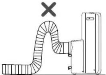
Simple line drawing of a vertical pipe with a small object inside, connected to a vertical support (no text or symbols)Discharge pipe can be installed based on user's requirement, while installation form as shown below should be avoided as it may lead to non-uniform exhaust.
natural_image
Diagram of a curved pipe system with a cross mark and labeled components (no text or symbols present)- If the length of the heat discharge pipe is less than 1 meter. It is recommended to use it with shortest length.
- When installing, heat discharge pipe should be as flat as possible. Do not lengthen the pipe or connect it with an other heat discharge pipe.
natural_image
Technical line drawing of a mechanical device with a coiled spring and mounting holes (no text or symbols)Operation Test
- Connect power and then press ON/OFF button on remote control to start the unit.
- Press mode button to select auto, cooling, dry, fan or heating function, and then check if the unit operates normally.
- If ambient temperature is below 16^ , the unit can't operate in cooling mode.
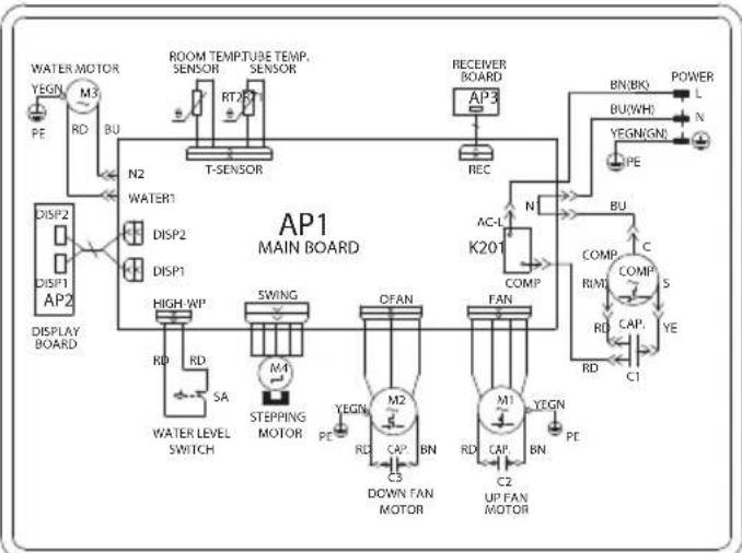
Wiring Diagram
The electric schematic diagram are subject to change without notice. Please refer to the one on the unit.
UL-C10EA-W
UL-C12EA-W
UL-C10UA-W
flowchart
graph TD
    A["AP1 MAIN BOARD"] --> B["ROOM TEMPTUBE TEMP. SENSOR"]
    A --> C["T-SENSOR"]
    A --> D["RECEIVER BOARD"]
    A --> E["K201"]
    A --> F["SWING"]
    A --> G["OFAN"]
    A --> H["UP FAN MOTOR"]
    B --> I["DISP1"]
    B --> J["DISP2"]
    B --> K["DISP3"]
    C --> L["AP2"]
    D --> M["POWER L"]
    D --> N["BU(WH) N"]
    D --> O["PE"]
    E --> P["AC-L"]
    E --> Q["FAN"]
    F --> R["COMP RMI"]
    F --> S["COMP S"]
    F --> T["CAP YE"]
    F --> U["C1"]
    F --> V["RD RD"]
    F --> W["PE PE"]
    A --> X["WATER MOTOR"]
    A --> Y["BEGN PE"]
    A --> Z["M3 RD BU"]
    A --> AA["N2 WATER1"]
    A --> AB["HIGH-WP RD SA"]
    A --> AC["WATER LEVEL SWITCH"]
    A --> AD["M4 STEPPING MOTOR PE"]
    A --> AE[M2 CAP BN RD C3 DOWN FAN MOTOR UP FAN MOTOR C2 UP FAN MOTOR UP FAN MOTOR UP FAN MOTOR UP FAN MOTOR UP FAN MOTOR UP FAN MOTOR UP FAN MOTOR UP FAN MOTOR UP FAN MOTOR UP FAN MOTOR UP FAN MOTOR UP FAN MOTOR UP FAN MOTOR UP FAN MOTOR UP FAN MOTOR UP FAN MOTOR UP FAN MOTOR UP FAN MOTOR UP FAN MOTOR UP FAN MOTOR UP FAN MOTOR UP FAN MOTOR UP FAN MOTOR UP FAN MOTOR UP FAN MOTOR UP FAN M1 RD CAP BN RD C2 UP FAN MOTOR UP FAN MOTOR UP FAN MOTOR UP FAN MOTOR UP FAN MOTOR UP FAN MOTOR UP FAN MOTOR UP FAN MOTOR UP FAN MOTOR UP FAN MOTOR UP FAN MOTOR UP FAN MOTOR UP FAN MOTOR UP FAN MOTOR UP FAN MOTOR UP FAN MOTOR UP FAN MOTOR UP FAN MOTOR UP FAN MOTOR UP FAN MOTOR UP FAN MOTOR UP FAN MOTOR UP FAN MOTOR UP FAN MOTOR UPFAN MOTOR UP FAN MOTOR UP FAN MOTOR UP FAN MOTOR UP FAN MOTOR UP FAN MOTOR UP FAN MOTOR UP FAN MOTOR UP FAN MOTOR UP FAN MOTOR UP FAN MOTOR UP FAN MOTOR UP FAN MOTOR UP FAN MOTOR UP FAN MOTOR UP FAN MOTOR UP FAN MOTOR UP FAN MOTOR UP FAN MOTOR UP FAN MOTOR UP FAN MOTOR UP FAN MOTOR UP FAN MOTOR UP FAN MOTOR UP FAN MOTOR UPFAN M1 RD CAP BN RD C2 UP FAN MOTOR UP FAN MOTOR UP FAN MOTOR UP FAN MOTOR UP FAN MOTOR UP FAN MOTOR UP FAN MOTOR UP FAN MOTOR UP FAN MOTOR UP FAN MOTOR UP FAN MOTOR UP FAN MOTOR UP FAN MOTOR UP FAN MOTOR UP FAN MOTOR UP FAN MOTOR UP FAN MOTOR UP FAN MOTOR UP FAN MOTOR UP FAN MOTOR UP FAN MOTOR UP FAN MOTOR UP FANC M1 RD CAP BN RD C2 UP FAN MOTOR UP FAN MOTOR UP FAN MOTOR UP FAN MOTOR UP FAN MOTOR UP FAN MOTOR UP FAN MOTOR UP FAN MOTOR UP FAN MOTOR UP FAN MOTOR UP FAN MOTOR UP FAN MOTOR UP FAN MOTOR UP FAN MOTOR UP FAN MOTOR UPFANC M1 RD CAP BN RD C2 UP FAN MOTOR UP FAN MOTOR UP FAN MOTOR UP FAN MOTOR UP FAN MOTOR UP FAN MOTOR UP FAN MOTOR UP FAN MOTOR UP FAN MOTOR UPFANC M1 RD CAP BN RD C2 UP FAN MOTOR UP FAN MOTOR OPFANC M2 RD CAP BN RD C3 DOWN FATN MOTOR OPFANC M3 RD CAP BN RD C4 DOWN FATN MOTOR OPFANC M4 RD CAP BN RD C5 DOWN FATN MOTOR OPFANC M5 RD CAP BN RD C6 DOWN FATN MOTOR OPFANC M6 RD CAP BN RD C7 DOWN FATN MOTOR OPFANC M7 RD CAP BN RD C8 DOWN FATN MOTOR OPFANC M8 RD CAP BN RD C9 DOWN FATN MOTOR OPFANC M9 RD CAP BN RD C10 DOWN FATN MOTOR OPFANC M10 RD CAP BN RD C11 DOWN FATN MOTOR OPFANC M11 RD CAP BN RD C12 DOWN FATN MOTOR OPFANC M12 RD CAP BN RD C13 DOWN FATN MOTOR OPFANC M13 RD CAP BN RD C14 DOWN FATN MOTOR OPFANC M14 RD CAP BN RD C15 DOWN FATN MOTOR OPFANC M15 RD CAP BN RD C16 DOWN FATN MOTOR OPFANC M16 RD CAP BN RD C17 DOWN FATN MOTOR OPFANC M17 RD CAP BN RD C18 DOWN FATN MOTOR OPFANC M18 RD CAP BN RD C19 DOWN FATN MOTOR OPFANC M19 RD CAP BN RD C20 DOWN FATN MOTOR OPFANC M20 RD CAP BN RD C21 DOWN FATN MOTOR OPFANC M21 RD CAP BN RD C22 DOWN FATN MOTOR OPFANC M22 RD CAP BN RD C23 DOWN FATN MOTOR OPFANC M23 RD CAP BN RD C24 DOWN FATN MOTOR OPFANC M24 RD CAP BN RD C25 DOWN FATN MOTOR OPFANC M25 RD CAP BN RD C26 DOWN FATN MOTOR OPFANC M26 RD CAP BN RD C27 DOWN FATN MOTOR OPFANC M27 RD CAP BN RD C28 DOWN FATN MOTOR OPFANC M28 RD CAP BN RD C29 DOWN FATN MOTOR OPFANC M29 RD CAP BN RD C30 DOWN FATN MOTOR OPFANC M30 RD CAP BN RD C31 DOWN FATN MOTOR OPFANC M31 RD CAP BN RD C32 DOWN FATN MOTOR OPFANC M32 RD CAP BN RD C33 DOWN FATN MOTOR OPFANC M33 RD CAP BN RD C34 DOWN FATN MOTOR OPFANC M34 RD CAP BN RD C35 DOWN FATN MOTOR OPFANC M35 RD CAP BN RD C36 DOWN FATN MOTOR OPFANC M36 RD CAP BN RD C37 DOWN FATN MOTOR OPFANC M37 RD CAP BN RD C38 DOWN FATN MOTOR OPFANC M38 RD CAP BN RD C39 DOWN FATN MOTOR OPFANC M39 RD CAP BN RD C40 DOWN FATN MOTOR OPFANC M40 RD CAP BN RD C41 DOWN FATN MOTOR OPFANC M41 RD CAP BN RD C42 DOWN FATN MOTOR OPFANC M42 RD CAP BN RD C43 DOWN FATN MOTOR OPFANC M43 RD CAP BN RD C44 DOWN FATN MOTOR OPFANC M44 RD CAP BN RD C45 DOWN FATN MOTOR OPFANC M45 RD CAP BN RD C46 DOWN FATN MOTOR OPFANC M46 RD CAP BN RD C47 DOWN FATN MOTOR OPFANC M47 RD CAP BN RD C48 DOWN FATN MOTOR OPFANC M48 RD CAP BN RD C49 DOWN FATN MOTOR OPFANC M49 RD CAP BN RD C50 DOWN FATN MOTOR OPFANC M50 RD CAP BN RD C51 DOWN FATN MOTOR OPFANC M51 RD CAP BN RD C52 DOWN FATN MOTOR OPFANC M52 RD CAP BN RD C53 DOWN FATN MOTOR OPFANC M53 RD CAP BN RD C54 DOWN FATN MOTOR OPFANC M54 RD CAP BN RD C55 DOWN FATN MOTOR OPFANC M55 RD CAP BN RD C56 DOWN FATN MOTOR OPFANC M56 RD CAP BN RD C57 DOWN FATN MOTOR OPFANC M57 RD CAP BN RD C58 DOWN FATN MOTOR OPFANC M58 RD CAP BN RD C59 DOWN FATN MOTOR OPFANC M59 RD CAP BN RD C60 DOWN FATN MOTOR OPFANC M60 RD CAP BN RD C61 DOWN FATN TORP OFC 1000/1000
    style AP1 MAIN BOARD fill:#f9f,stroke:#333
    style AP1 MAIN BOARD fill:#ccf,stroke:#333
    style AP1 MAIN BOARD fill:#cfc,stroke:#333
    style AP1 MAIN BOARD fill:#fcc,stroke:#333
    style AP1 MAIN BOARD fill:#cff,stroke:#333
    style AP1 MAIN BOARD fill:#ffc,stroke:#333
    style AP1 MAIN BOARD fill:#cfc,stroke:#333
    style AP1 MAIN BOARD fill:#fcc,stroke:#333
    style AP1 MAIN BOARD fill:#cfc,stroke:#333
    style AP1 MAIN BOARD fill:#fcc,stroke:#333
    style AP1 MAIN BOARD fill:#cfc,stroke:#333
    style AP1 MAIN BOARD fill:#cfc,stroke:#333
    style AP1 MAIN BOARD fill:#cfc,stroke:#333
    style AP1 MAIN BOARD fill:#cfc,stroke:#333
    style AP1 MAIN BOARD fill:#cfc,stroke:#333
    style AP1 MAIN BOARD fill:#cfc,stroke:#333
    style AP1 MAIN BOARD fill:fill:#fff,stroke:#ccc
    style AP1 MAIN BOARD fill:fill:#fff,stroke:#ccc
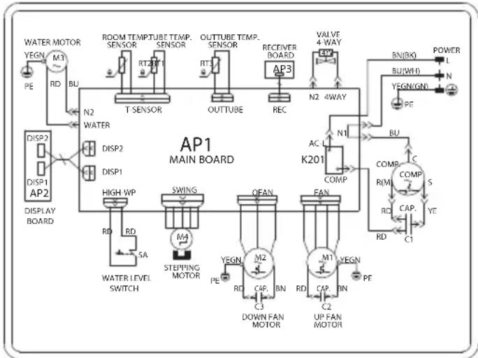
UL-CY12EA-W

flowchart
graph TD
    A["AP1 MAIN BOARD"] --> B["ROOM TEMP. TUBE TEMP. SENSOR"]
    A --> C["OUTTUBE TEMP. SENSOR"]
    A --> D["RECEIVER BOARD"]
    A --> E["VALVE 4-WAY"]
    A --> F["AC-1 K201"]
    A --> G["COMP"]
    A --> H["RIM1 COMP"]
    A --> I["CAP. UP FAN MOTOR"]
    A --> J["UP FAN MOTOR"]
    A --> K["UP FAN MOTOR"]
    A --> L["UP FAN MOTOR"]
    A --> M["UP FAN MOTOR"]
    A --> N["UP FAN MOTOR"]
    A --> O["UP FAN MOTOR"]
    A --> P["UP FAN MOTOR"]
    A --> Q["UP FAN MOTOR"]
    A --> R["UP FAN MOTOR"]
    A --> S["UP FAN MOTOR"]
    A --> T["UP FAN MOTOR"]
    A --> U["UP FAN MOTOR"]
    A --> V["UP FAN MOTOR"]
    A --> W["UP FAN MOTOR"]
    A --> X["UP FAN MOTOR"]
    A --> Y["UP FAN MOTOR"]
    A --> Z["UP FAN MOTOR"]
    A --> AA["UP FAN MOTOR"]
    A --> AB["UP FAN MOTOR"]
    A --> AC["UP FAN MOTOR"]
    A --> AD["UP FAN MOTOR"]
    A --> AE["UP FAN MOTOR"]
    A --> AF["UP FAN MOTOR"]
    A --> AG["UP FAN MOTOR"]
    A --> AH["UP FAN MOTOR"]
    A --> AI["UP FAN MOTOR"]
    A --> AJ["UP FAN MOTOR"]
    A --> AK["UP FAN MOTOR"]
    A --> AL["UP FAN MOTOR"]
    A --> AM["UP FAN MOTOR"]
    A --> AN["UP FAN MOTOR"]
    A --> AO["UP FAN MOTOR"]
    A --> AP["UP FAN MOTOR"]
    A --> AQ["UP FAN MOTOR"]
    A --> AR["UP FAN MOTOR"]
    A --> AS["UP FAN MOTOR"]
    A --> AT["UP FAN MOTOR"]
    A --> AU["UP FAN MOTOR"]
    A --> AV["UP FAN MOTOR"]
    A --> AW["UP FAN MOTOR"]
    A --> AX["UP FAN MOTOR"]
    A --> AY["UP FAN MOTOR"]
    A --> AZ["UP FAN MOTOR"]
    A --> BA["UP FAN MOTOR"]
    A --> BB["UP FAN MOTOR"]
    A --> BC["UP FAN MOTOR"]
    A --> BD["UP FAN MOTOR"]
    A --> BE["UP FAN MOTOR"]
    A --> BF["UP FAN MOTOR"]
    A --> BG["UP FAN MOTOR"]
    A --> BH["UP FAN MOTOR"]
    A --> BI["UP FAN MOTOR"]
    A --> BJ["UP FAN MOTOR"]
    A --> BK["UP FAN MOTOR"]
    A --> BL["UP FAN MOTOR"]
    A --> BM["UP FAN MOTOR"]
    A --> BN["UP FAN MOTOR"]
    A --> BO["UP FAN MOTOR"]
    A --> BP["UP FAN MOTOR"]
    A --> BQ["UP FAN MOTOR"]
    A --> BR["UP FAN MOTOR"]
    A --> BS["UP FAN MOTOR"]
    A --> BT["UP FAN MOTOR"]
    A --> BU["UP FAN MOTOR"]
    A --> BV["UP FAN MOTOR"]
    A --> BW["UP FAN MOTOR"]
    A --> BX["UP FAN MOTOR"]
    A --> BY["UP FAN MOTOR"]
Specialist's Manual
Aptitude requirement for maintenance personnel (repairs should be done only by specialists).
-
Any person who is involved with working on or breaking into a refrigerant circuit should hold a current valid certificate from an industry-accredited assessment authority, which authorises their competence to handle refrigerants safely in accordance with an industry recognised assessment specification.
-
Servicing shall only be performed as recommended by the equipment manufacturer. Maintenance and repair requiring the assistance of other skilled personnel shall be carried out under the supervision of the person competent in the use of flammable refrigerants.
Safety preparation work
The maximum refrigerant charge amount is shown on the following table. (Note: Please refer to the nameplate for the charging quantity of R290).
| Room area (m2) 4 11 15 | |||
| Maximum charge (kg) <0.152 | 0.225 | 0.304 |
Prior to beginning work on systems containing flammable refrigerants, safety checks are necessary to ensure that the risk of ignition is minimised. For repair to the refrigerating system, the following precautions shall be complied with prior to conducting work on the system.
Work procedure
Work shall be undertaken under a controlled procedure so as to minimise the risk of a flammable gas or vapour being present while the work is being performed.
General work area
All maintenance staff and others working in the local area shall be instructed on the nature of work being carried out. Work in confined spaces shall be avoided. The area around the workspace shall be sectioned off. Ensure that the conditions within the area have been made safe by control of flammable material
Checking for presence of refrigerant
The area shall be checked with an appropriate refrigerant detector prior to and during work, to ensure the technician is aware of potentially toxic or flammable atmospheres. Ensure that the leak detection equipment being used is suitable for use with all applicable refrigerants, i.e. non-sparking, adequately sealed or intrinsically safe.
Presence of fire extinguisher
If any hot work is to be conducted on the refrigeration equipment or any associated parts, appropriate fire extinguishing equipment shall be available to hand. Have a dry powder or CO2 fire extinguisher adjacent to the charging area.
No ignition sources
No person carrying out work in relation to a refrigeration system which involves exposing any pipe work shall use any sources of ignition in such a manner that it may lead to the risk of fire or explosion.
All possible ignition sources, including cigarette smoking, should be kept sufficiently far away from the site of installation, repairing, removing and disposal, during which refrigerant can possibly be released to the surrounding space. Prior to work taking place, the area around the equipment is to be surveyed to make sure that there are no flammable hazards or ignition risks. "No Smoking" signs shall be displayed.
Ventilated area
Ensure that the area is in the open or that it is adequately ventilated before breaking into the system or conducting any hot work. A degree of ventilation shall continue during the period that the work is carried out. The ventilation should safely disperse any released refrigerant and preferably expel it externally into the atmosphere.
Checks to the refrigeration equipment
Where electrical components are being changed, they shall be fit for the purpose and to the correct specification. At all times the manufacturer's maintenance and service guidelines shall be followed.
If in doubt, consult the manufacturer's technical department for assistance.
The following checks shall be applied to installations using flammable refrigerants:
- The actual refrigerant charge is in accordance with the room size within which the refrigerant containing parts are installed;
- The ventilation machinery and outlets are operating adequately and are not obstructed;
- If an indirect refrigerating circuit is being used, the secondary circuit shall be checked for the presence of refrigerant;
- Marking to the equipment continues to be visible and legible. Markings and signs that are illegible shall be corrected;
- Refrigeration pipe or components are installed in a position where they are unlikely to be exposed to any substance which may corrode refrigerant containing components, unless the components are constructed of materials which are inherently resistant to being corroded or are suitably protected against being so corroded.
Checks to electrical devices
Repair and maintenance to electrical components shall include initial safety checks and component inspection procedures. If a fault exists that could compromise safety, then no electrical supply shall be connected to the circuit until it is satisfactorily dealt with. If the fault cannot be corrected immediately but it is necessary to continue operation, an adequate temporary solution shall be used. This shall be reported to the owner of the equipment so all parties are advised.
Initial safety checks shall include:
- That capacitors are discharged: this shall be done in a safe manner to avoid possibility of sparking;
- That no live electrical components and wiring are exposed while charging, recovering or purging the system;
• That there is continuity of earth bonding.
Repairs to sealed components
During repairs to sealed components, all electrical supplies shall be disconnected from the equipment being worked upon prior to any removal of sealed covers, etc. If it is absolutely necessary to have an electrical supply to equipment during servicing, then a permanently operating form of leak detection shall be located at the most critical point to warn of a potentially hazardous situation.
Particular attention shall be paid to the following to ensure that by working on electrical components, the casing is not altered in such a way that the level of protection is affected. This shall include damage to cables, excessive number of connections, terminals not made to original specification, damage to seals, incorrect fitting of glands, etc.
- Ensure that the apparatus is mounted securely.
- Ensure that seals or sealing materials have not degraded to the point that they no longer serve the purpose of preventing the ingress of flammable atmospheres. Replacement parts shall be in accordance with the manufacturer's specifications.
NOTE:
The use of silicon sealant can inhibit the effectiveness of some types of leak detection equipment. Intrinsically safe components do not have to be isolated prior to working on them.
Repair to intrinsically safe components
Do not apply any permanent inductive or capacitance loads to the circuit without ensuring that this will not exceed the permissible voltage and current permitted for the equipment in use.
Intrinsically safe components are the only types that can be worked on while live in the presence of a flammable atmosphere. The test apparatus shall be at the correct rating.
Replace components only with parts specified by the manufacturer. Other parts may result in the ignition of refrigerant in the atmosphere from a leak.
Cabling
Check that cabling will not be subject to wear, corrosion, excessive pressure, vibration, sharp edges or any other adverse environmental effects. The check shall also take into account the effects of aging or continual vibration from sources such as compressors or fans.
Detection of flammable refrigerants
Under no circumstances shall potential sources of ignition be used in the searching for or detection of refrigerant leaks. A halide torch (or any other detector using a naked flame) shall not be used.
Leak detection methods
The following leak detection methods are deemed acceptable for all refrigerant systems.
Electronic leak detectors may be used to detect refrigerant leaks but, in the case of flammable refrigerants, the sensitivity may not be adequate, or may need re-calibration. (Detection equipment shall be calibrated in a refrigerant-free area.) Ensure that the detector is not a potential source of ignition and is suitable for the refrigerant used. Leak detection equipment shall be set at a percentage of the LFL of the refrigerant and shall be calibrated to the refrigerant employed, and the appropriate percentage of gas (25 % maximum) is confirmed.
Leak detection fluids are suitable for use with most refrigerants but the use of detergents containing chlorine shall be avoided as the chlorine may react with the refrigerant and corrode the copper pipe-work.
If a leak is suspected, all naked flames shall be removed/extinguished. If a leakage of refrigerant is found which requires brazing, all of the refrigerant shall be recovered from the system, or isolated (by means of shut off valves) in a part of the system remote from the leak. For appliances containing flammable refrigerants, oxygen free nitrogen (OFN) shall then be purged through the system both before and during the brazing process
Removal and evacuation
When breaking into the refrigerant circuit to make repairs – or for any other purpose – conventional procedures shall be used. However, for flammable refrigerants it is important that best practice is followed since flammability is a consideration. The following procedure shall be adhered to:
- remove refrigerant;
• purge the circuit with inert gas; - evacuate;
• purge again with inert gas; - open the circuit by cutting or brazing.
The refrigerant charge shall be recovered into the correct recovery cylinders. For appliances containing flammable refrigerants, the system shall be "flushed" with OFN to render the unit safe. This process may need to be repeated several times. Compressed air or oxygen shall not be used for purging refrigerant systems.
For appliances containing flammable refrigerants, flushing shall be achieved by breaking the vacuum in the system with OFN and continuing to fill until the working pressure is achieved, then venting to atmosphere, and finally pulling down to a vacuum.
This process shall be repeated until no refrigerant is within the system. When the final OFN charge is used, the system shall be vented down to atmospheric pressure to enable work to take place. This operation is absolutely vital if brazing operations on the pipe-work are to take place. Ensure that the outlet of the vacuum pump is not close to any ignition sources and that ventilation is available.
Charging procedures
In addition to conventional charging procedures, the following requirements shall be followed.
- Ensure that contamination of different refrigerants does not occur when using charging equipment. Hoses or lines shall be as short as possible to minimise the amount of refrigerant contained in them.
• Cylinders shall be kept upright. - Ensure that the refrigeration system is earthed prior to charging the system with refrigerant.
- Label the system when charging is complete (if not already).
- Extreme care shall be taken not to overfill the operefrigeration system. Prior to recharging the system, it shall be pressure-tested with the appropriate purging gas.
The system shall be leak-tested on completion of charging but prior to commissioning. A follow up leak test shall be carried out prior to leaving the site.
Decommissioning
Before carrying out this procedure, it is essential that the technician is completely familiar with the equipment and all its detail. It is
recommended good practice that all refrigerants are recovered safely. Prior to the task being carried out, an oil and refrigerant sample shall be taken in case analysis is required prior to reuse of reclaimed refrigerant. It is essential that electrical power is available before the task is commenced.
a. Become familiar with the equipment and its operation.
b. Isolate system electrically.
c. Before attempting the procedure, ensure that:
- mechanical handling equipment is available, if required, for handling refrigerant cylinders;
– all personal protective equipment is available and being used correctly;
– the recovery process is supervised at all times by a competent person;
– recovery equipment and cylinders conform to the appropriate standards.
d. Pump down refrigerant system, if possible.
e. If a vacuum is not possible, make a manifold so that refrigerant can be removed from various parts of the system.
f. Make sure that cylinder is situated on the scales before recovery takes place.
g. Start the recovery machine and operate in accordance with manufacturer's instructions.
h. Do not overfill cylinders. (No more than 80% volume liquid charge).
i. Do not exceed the maximum working pressure of the cylinder, even temporarily.
j. When the cylinders have been filled correctly and the process completed, make sure that the cylinders and the equipment are removed from site promptly and all isolation valves on the equipment are closed off.
k. Recovered refrigerant shall not be charged into another refrigeration system unless it has been cleaned and checked.
Labelling
Equipment shall be labelled stating that it has been decommissioned and emptied of refrigerant. The label shall be dated and signed. For appliances containing flammable refrigerants, ensure that there are labels on the equipment stating the equipment contains flammable refrigerant.
Recovery
When removing refrigerant from a system, either for servicing or decommissioning, it is recommended good practice that all refrigerants are removed safely.
When transferring refrigerant into cylinders, ensure that only appropriate refrigerant recovery cylinders are employed. Ensure that the correct number of cylinders for holding the total system charge are available. All cylinders to be used are designated for the recovered refrigerant and labelled for that refrigerant (i.e. special cylinders for the recovery of refrigerant). Cylinders shall be complete with pressure-relief valve and associated shut-off valves in good working order. Empty recovery cylinders are evacuated and, if possible, cooled before recovery occurs.
The recovery equipment shall be in good working order with a set of instructions concerning the equipment that is at hand and shall be suitable for the recovery of all appropriate refrigerants including, when applicable, flammable refrigerants. In addition, a set of calibrated weighing scales shall be available and in good working order. Hoses shall be complete with leak-free disconnect couplings and in good condition. Before using the recovery machine, check that it is in satisfactory working order, has been properly maintained and that any associated electrical components are sealed to prevent ignition in the event of a refrigerant release. Consult manufacturer if in doubt.
The recovered refrigerant shall be returned to the refrigerant supplier in the correct recovery cylinder, and the relevant waste transfer note arranged. Do not mix refrigerants in recovery units and especially not in cylinders.
If compressors or compressor oils are to be removed, ensure that they have been evacuated to an acceptable level to make certain that flammable refrigerant does not remain within the lubricant. The evacuation process
shall be carried out prior to returning the compressor to the suppliers. Only electric heating to the compressor body shall be employed to accelerate this process. When oil is drained from a system, it shall be carried out safely.
Technical specification
| Model UL-C10EA-W UL-C12EA-W UL-Y12EA-W | ||||
| Power Supply 220 – 240V AC, 50Hz 220 – 240V AC, 50Hz 220 – 240V AC, 50Hz | ||||
| Energy Efficiency Class | Cooling A+ A A | |||
| Heating N/A N/A A+ | ||||
| Running Power Consumption | Cooling (W) 935 1345 1345 | |||
| Heating (W) | N/A N/A 1190 | |||
| Standby Power Consumption (W) | 0,5 | 0,5 | 0,5 | |
| Cooling Capacity (W) | 2900 3520 3520 | |||
| Heating Capacity (W) | N/A N/A 3100 | |||
| Noise Level dB(A) (Fan speed: High/Medium/Low) | 65/64/62 | 65/64/62 | 65/64/62 | |
| Air Flow (High/Medium/Low) ( m^3/h ) | 385/355/325 | 385/355/325 | 385/355/325 | |
| Operating Temperature Range (°C) | 16 ~ 30 | 16 ~ 30 | 16 ~ 30 | |
| Room Size ( m^2 ) | 13 ~ 19 | 16 ~ 23 | 16 ~ 23 | |
| Size (W x D x H in mm) | 393 x 425 x 804 | 393 x 425 x 804 | 393 x 425 x 804 | |
| Weight (kg) | 32,5 | 34,5 | 35,0 | |
| Refrigerant | R290 R290 R290 | |||
Technical specifications are subject to change without notice.
Ausnahmeklauseln

www.sharpconsumer.com/contact/

www.sharpconsumer.com/support/

www.sharpconsumer.com/documents-of-conformity/
natural_image
Diagram showing a hand pressing down on a device with an inset close-up of a textured surface (no text or symbols)- Filterreinigung
natural_image
Line drawing of a hand holding a knife on a grid-patterned surface (no text or symbols)HINWEIS
natural_image
Diagram of a portable air conditioner unit with attached cable and two circular insets showing internal components (no text or labels)natural_image
Technical line drawing of a device rear panel with internal components and mounting holes (no text or symbols)Wasser ablassen
natural_image
Technical line drawing of two industrial devices with a close-up inset showing a mechanical component (no text or symbols)natural_image
Diagram of a device with a circular inset showing a mechanical component and a magnified view of the internal structure (no text or symbols)natural_image
Line drawing of a portable air conditioner unit with ventilation duct and cooling fan (no text or symbols)ACHTUNG:
natural_image
Diagram of a pipe connection with insulation and support structure (no text or symbols)natural_image
Pure technical line drawing of a pipe or channel system without any text, numbers, or symbolsnatural_image
Diagram of a curved duct system with a warning symbol (X) above it, no text or labels present.natural_image
Technical line drawing of a mechanical device with a coiled tube and mounting holes (no text or symbols)Betriebstest

www.sharpconsumer.com/contact/

www.sharpconsumer.com/support/

www.sharpconsumer.com/documents-of-conformity/
natural_image
Diagram showing a hand pressing down on a textured panel with an arrow indicating force, and a magnified inset showing the interior detail (no text or symbols)- Limpie el filtro
natural_image
Illustration of hands using a tool to clean or prepare a flat surface (no text or symbols)NOTA
natural_image
Diagram of a device with labeled parts and wiring, showing internal components without any readable text or symbols.natural_image
Diagram of a device rear panel with ventilation grille and hanging connectors (no text or symbols)Drenaje de agua
natural_image
Diagram showing two views of a portable air conditioner unit with a close-up inset view of the front panel (no text or symbols present)natural_image
Diagram of a device showing internal components and a circular arrow indicating rotation (no text or symbols present)natural_image
Line drawing of a portable air conditioner unit with ventilation duct and cooling fan (no text or symbols)ATENCIÓN:
natural_image
Diagram of a pipe connection with a vertical support structure (no text or symbols)natural_image
Pure electrical circuit lines without any symbolsnatural_image
Diagram of a curved duct system with a switch and labeled components (no text or symbols present)natural_image
Technical line drawing of a mechanical device with a coiled spring and mounting holes (no text or symbols)AVERTISSE-MENT

www.sharpconsumer.com/contact/

www.sharpconsumer.com/support/

www.sharpconsumer.com/documents-of-conformity/
natural_image
Diagram showing a device with a downward arrow and magnified detail of its interior structure (no text or symbols)- Nettoyer le filtre
natural_image
Illustration of a hand using a tool to cut or mark on a grid-patterned surface (no text or symbols)REMARQUE
natural_image
Diagram of a portable air conditioner unit with attached cable and two circular components (no text or symbols)natural_image
Technical line drawing of a device rear panel with ventilation grille and hanging connectors (no text or symbols)Drainage de l'eau
natural_image
Technical line drawing of a two-part industrial device with a close-up inset showing a mechanical component (no text or symbols)natural_image
Diagram of a mechanical device with a circular inset showing a threaded component and a magnified view of the internal structure (no text or symbols)natural_image
Line drawing of a portable air conditioner unit with ventilation grilles and cooling fans (no text or symbols)ATTENTION :
natural_image
Diagram of a pipe connection with insulation and support structure (no text or symbols)natural_image
Simple line drawing of a vertical pipe or channel with a small inset component, no text or symbols present.natural_image
Diagram of a curved duct system with a warning symbol (X) above it, no text or labels present.natural_image
Technical line drawing of a mechanical device with a coiled tube and mounting bracket (no text or symbols)CE and UKCA statement:

www.sharpconsumer.com/contact/

www.sharpconsumer.com/support/

www.sharpconsumer.com/documents-of-conformity/
natural_image
Diagram showing a hand inserting a component into a device with an inset close-up of the component (no text or symbols)- Pulire il filtro
natural_image
Illustration of hands using a knife to cut a flat surface on a grid (no text or symbols)NOTA
natural_image
Diagram of a portable air conditioner unit with attached cable and two circular insets showing internal components (no text or labels)natural_image
Technical line drawing of a device rear panel with ventilation duct and handle (no text or symbols)Scaricare l'acqua
natural_image
Diagram of two industrial air purifiers with labeled components and a magnified inset showing a mechanical component (no text or symbols present)natural_image
Diagram of a washing machine showing internal components and a circular component with a knob (no text or symbols)natural_image
Line drawing of a portable air conditioner unit with ventilation duct and control knobs (no text or symbols)ATTENZIONE:
natural_image
Diagram of a pipe connection with insulation and support structure (no text or symbols)natural_image
Simple line drawing of a vertical pipe with a small attached component, no text or symbols present.natural_image
Diagram of a curved duct system with a cross mark and labeled components (no text or symbols present)natural_image
Technical line drawing of a mechanical device with a coiled spring and mounting holes (no text or symbols)flowchart
graph TD
    A["AP1 MAIN BOARD"] --> B["ROOM TEMPTUBE TEMP. SENSOR"]
    A --> C["OUTUBE TEMP. SENSOR"]
    A --> D["RECEIVER BOARD"]
    A --> E["VALVE 4-WAY"]
    A --> F["K201"]
    A --> G["POWER"]
    A --> H["AC-1"]
    A --> I["COMP"]
    A --> J["RIM"]
    A --> K["CAP"]
    A --> L["UP FAN MOTOR"]
    A --> M["UP FAN MOTOR"]
    A --> N["UP FAN MOTOR"]
    A --> O["UP FAN MOTOR"]
    A --> P["UP FAN MOTOR"]
    A --> Q["UP FAN MOTOR"]
    A --> R["UP FAN MOTOR"]
    A --> S["UP FAN MOTOR"]
    A --> T["UP FAN MOTOR"]
    A --> U["UP FAN MOTOR"]
    A --> V["UP FAN MOTOR"]
    A --> W["UP FAN MOTOR"]
    A --> X["UP FAN MOTOR"]
    A --> Y["UP FAN MOTOR"]
    A --> Z["UP FAN MOTOR"]
    A --> AA["UP FAN MOTOR"]
    A --> AB["UP FAN MOTOR"]
    A --> AC["UP FAN MOTOR"]
    A --> AD["UP FAN MOTOR"]
    A --> AE["UP FAN MOTOR"]
    A --> AF["UP FAN MOTOR"]
    A --> AG["UP FAN MOTOR"]
    A --> AH["UP FAN MOTOR"]
    A --> AI["UP FAN MOTOR"]
    A --> AJ["UP FAN MOTOR"]
    A --> AK["UP FAN MOTOR"]
    A --> AL["UP FAN MOTOR"]
    A --> AM["UP FAN MOTOR"]
    A --> AN["UP FAN MOTOR"]
    A --> AO["UP FAN MOTOR"]
    A --> AP["UP FAN MOTOR"]
    A --> AQ["UP FAN MOTOR"]
    A --> AR["UP FAN MOTOR"]
    A --> AS["UP FAN MOTOR"]
    A --> AT["UP FAN MOTOR"]
    A --> AU["UP FAN MOTOR"]
    A --> AV["UP FAN MOTOR"]
    A --> AW["UP FAN MOTOR"]
    A --> AX["UP FAN MOTOR"]
    A --> AY["UP FAN MOTOR"]
    A --> AZ["UP FAN MOTOR"]
    A --> BA["UP FAN MOTOR"]
    A --> BB["UP FAN MOTOR"]
    A --> BC["UP FAN MOTOR"]
    A --> BD["UP FAN MOTOR"]
    A --> BE["UP FAN MOTOR"]
    A --> BF["UP FAN MOTOR"]
    A --> BG["UP FAN MOTOR"]
    A --> BH["UP FAN MOTOR"]
    A --> BI["UP FAN MOTOR"]
    A --> BJ["UP FAN MOTOR"]
    A --> BK["UP FAN MOTOR"]
    A --> BL["UP FAN MOTOR"]
    A --> BM["UP FAN MOTOR"]
    A --> BN["UP FAN MOTOR"]
    A --> BO["UP FAN MOTOR"]
    A --> BP["UP FAN MOTOR"]
    A --> BQ["UP FAN MOTOR"]
    A --> BR["UP FAN MOTOR"]
    A --> BS["UP FAN MOTOR"]
    A --> BT["UP FAN MOTOR"]
    A --> BU["UP FAN MOTOR"]
    A --> BV["UP FAN MOTOR"]
    A --> BW["UP FAN MOTOR"]
    A --> BX["UP FAN MOTOR"]
    A --> BY["UP FAN MOTOR"]

www.sharpconsumer.com/contact/

www.sharpconsumer.com/support/

www.sharpconsumer.com/documents-of-conformity/
natural_image
Diagram showing a hand pressing down on a textured panel with an inset close-up of the lid (no text or symbols)- Wyczyść filtr
natural_image
Illustration of hands using a knife to cut a rectangular object on a grid (no text or symbols)UWAGA
natural_image
Diagram of a portable air conditioner unit with attached cable and two circular components (no text or symbols)natural_image
Technical line drawing of a mechanical component with no visible text or symbolsOdprowadzanie kondensatu
natural_image
Technical line drawing of two industrial air purifiers with a close-up inset showing a mechanical component (no text or symbols)natural_image
Diagram of a device with a circular arrow pointing to a connector, showing internal components and no text or symbols.natural_image
Line drawing of a portable air conditioner unit with ventilation duct and cooling fan (no text or symbols)OSTRZEŻENIE:
natural_image
Diagram of a pipe connection with a vertical support and horizontal supports (no text or symbols)natural_image
Pure technical line drawing of a pipe or channel system without any text, numbers, or symbolsnatural_image
Diagram of a curved pipe system with a switch and labeled components (no text or symbols present)natural_image
Technical line drawing of a mechanical device with a coiled cylindrical component and mounting holes (no text or symbols)Rozruch testowy
flowchart
graph TD
    A["AP1 MAIN BOARD"] --> B["DISP1 AP2"]
    B --> C["DISP2"]
    C --> D["DISP1"]
    D --> E["AP2"]
    E --> F["DISP2"]
    F --> G["AP2"]
    G --> H["DISP1"]
    H --> I["AP2"]
    I --> J["DISP2"]
    J --> K["AP2"]
    K --> L["DISP1"]
    L --> M["AP2"]
    M --> N["DISP2"]
    N --> O["AP2"]
    O --> P["DISP1"]
    P --> Q["AP2"]
    Q --> R["DISP2"]
    R --> S["AP2"]
    S --> T["DISP1"]
    T --> U["AP2"]
    U --> V["DISP2"]
    V --> W["AP2"]
    W --> X["DISP1"]
    X --> Y["AP2"]
    Y --> Z["DISP2"]
    Z --> AA["AP2"]
    AA --> AB["DISP1"]
    AB --> AC["AP2"]
    AC --> AD["DISP2"]
    AD --> AE["AP2"]
    AE --> AF["DISP1"]
    AF --> AG["AP2"]
    AG --> AH["DISP2"]
    AH --> AI["AP2"]
UL-CY12EA-W
flowchart
graph TD
    A["AP1 MAIN BOARD"] --> B["ROOM TEMPTUBE TEMP. SENSOR"]
    A --> C["OUTTUBE TEMP. SENSOR"]
    A --> D["RECEIVER BOARD"]
    A --> E["VALVE 4-WAY"]
    B --> F["T SENSOR"]
    C --> G["OUTTUBE"]
    D --> H["REC"]
    E --> I["K201"]
    F --> J["N2 WATER"]
    G --> K["N2 4WAY"]
    H --> L["N2 4WAY"]
    I --> M["N1 COMP"]
    J --> N["N2 WATER"]
    K --> O["N2 4WAY"]
    L --> P["POWER"]
    M --> Q["R(M)"]
    N --> R["S"]
    O --> S["CAP, YE"]
    P --> T["CAP, RN"]
    Q --> U["UP FAN MOTOR"]
    R --> V["UP FAN MOTOR"]
    S --> W["UP FAN MOTOR"]
    T --> X["UP FAN MOTOR"]
    U --> Y["UP FAN MOTOR"]
    V --> Z["UP FAN MOTOR"]
    W --> AA["UP FAN MOTOR"]
    X --> AB["UP FAN MOTOR"]
    Y --> AC["UP FAN MOTOR"]
    Z --> AD["UP FAN MOTOR"]
natural_image
Warning sign depicting a flame inside a triangle (no text or symbols)
www.sharpconsumer.com/contact/

www.sharpconsumer.com/support/

www.sharpconsumer.com/documents-of-conformity/
sharpconsumer.com/documents-of-conformity/
Conteúdo da caixa
NOTA
natural_image
Diagram showing a hand pressing down on a device panel with an inset close-up of the lid (no text or symbols)natural_image
Illustration of hands using a tool to cut or spread a rectangular sheet on a grid (no text or symbols)NOTA
natural_image
Diagram of a portable air conditioner unit with attached cable and two circular insets showing internal components (no text or labels)natural_image
Diagram of a portable air conditioner unit with ventilation grille and hose (no text or labels)Drenagem de água
natural_image
Diagram of two electronic devices with ventilation grilles and a close-up inset showing a mechanical component (no text or symbols)natural_image
Diagram of a device showing a button on the left and internal components with a magnified view of the next component (no text or symbols present)natural_image
Line drawing of a portable air conditioner unit with ventilation duct and buttons (no text or symbols)ATENÇÃO:
natural_image
Diagram of a pipe connection with insulation and support structure (no text or symbols)natural_image
Simple line drawing of a vertical pipe with a small attached component, no text or symbols presentnatural_image
Diagram of a curved duct system with a cross mark and labeled components (no text or symbols present)natural_image
Technical line drawing of a mechanical device with a coiled spring and mounting holes (no text or symbols)Operação de teste
flowchart
graph TD
    A["AP1 MAIN BOARD"] --> B["ROOM TEMPTUBE TEMP. SENSOR"]
    A --> C["OUTUBE TEMP. SENSOR"]
    A --> D["RECEIVER BOARD"]
    A --> E["VALVE 4-WAY"]
    A --> F["K201"]
    A --> G["POWER"]
    A --> H["AC-1"]
    A --> I["COMP"]
    A --> J["RIM"]
    A --> K["CAP"]
    A --> L["UP FAN MOTOR"]
    A --> M["UP FAN MOTOR"]
    A --> N["UP FAN MOTOR"]
    A --> O["UP FAN MOTOR"]
    A --> P["UP FAN MOTOR"]
    A --> Q["UP FAN MOTOR"]
    A --> R["UP FAN MOTOR"]
    A --> S["UP FAN MOTOR"]
    A --> T["UP FAN MOTOR"]
    A --> U["UP FAN MOTOR"]
    A --> V["UP FAN MOTOR"]
    A --> W["UP FAN MOTOR"]
    A --> X["UP FAN MOTOR"]
    A --> Y["UP FAN MOTOR"]
    A --> Z["UP FAN MOTOR"]
    A --> AA["UP FAN MOTOR"]
    A --> AB["UP FAN MOTOR"]
    A --> AC["UP FAN MOTOR"]
    A --> AD["UP FAN MOTOR"]
    A --> AE["UP FAN MOTOR"]
    A --> AF["UP FAN MOTOR"]
    A --> AG["UP FAN MOTOR"]
    A --> AH["UP FAN MOTOR"]
    A --> AI["UP FAN MOTOR"]
    A --> AJ["UP FAN MOTOR"]
    A --> AK["UP FAN MOTOR"]
    A --> AL["UP FAN MOTOR"]
    A --> AM["UP FAN MOTOR"]
    A --> AN["UP FAN MOTOR"]
    A --> AO["UP FAN MOTOR"]
    A --> AP["UP FAN MOTOR"]
    A --> AQ["UP FAN MOTOR"]
    A --> AR["UP FAN MOTOR"]
    A --> AS["UP FAN MOTOR"]
    A --> AT["UP FAN MOTOR"]
    A --> AU["UP FAN MOTOR"]
    A --> AV["UP FAN MOTOR"]
    A --> AW["UP FAN MOTOR"]
    A --> AX["UP FAN MOTOR"]
    A --> AY["UP FAN MOTOR"]
    A --> AZ["UP FAN MOTOR"]
    A --> BA["UP FAN MOTOR"]
    A --> BB["UP FAN MOTOR"]
    A --> BC["UP FAN MOTOR"]
    A --> BD["UP FAN MOTOR"]
    A --> BE["UP FAN MOTOR"]
    A --> BF["UP FAN MOTOR"]
    A --> BG["UP FAN MOTOR"]
    A --> BH["UP FAN MOTOR"]
    A --> BI["UP FAN MOTOR"]
    A --> BJ["UP FAN MOTOR"]
    A --> BK["UP FAN MOTOR"]
    A --> BL["UP FAN MOTOR"]
    A --> BM["UP FAN MOTOR"]
    A --> BN["UP FAN MOTOR"]
    A --> BO["UP FAN MOTOR"]
    A --> BP["UP FAN MOTOR"]
    A --> BQ["UP FAN MOTOR"]
    A --> BR["UP FAN MOTOR"]
    A --> BS["UP FAN MOTOR"]
    A --> BT["UP FAN MOTOR"]
    A --> BU["UP FAN MOTOR"]
    A --> BV["UP FAN MOTOR"]
    A --> BW["UP FAN MOTOR"]
    A --> BX["UP FAN MOTOR"]
    A --> BY["UP FAN MOTOR"]
Manual do especialista
Sharp Consumer Electronics Poland sp. z o.o.
Ostaszewo 57B, 87-148 Lysomice, Poland
Made in China
SDA/MAN/0195
www.sharpconsumer.eu
SHARP

- User manual
- The Refrigerant
- Warning:
- Important safety instructions
- Please, read these safety instructions and respect the following warnings before the appliance is operated:
- In order to prevent fi re always keep candles and other open fl ames away from this product.
- Operation Environment:
- Disposal of this equipment and batteries
- CE and UKCA statement:
- Contents of the Box
- NOTE
- Part Names
- Control Panel
- NOTE:
- Operation of Control Panel
- ON/OFF button
- + / - button
- Fan button
- Mode button
- Timer button
- Swing
- Remote control
- Remote control buttons
- Remote control display
- Remote control functions
- +/- button
- SWING button
- SLEEP button
- Functions by Combination Buttons
- Child lock function
- Temperature display switchover function
- Light function
- Installation of batteries
- Care and Maintenance
- WARNING!
- Clean outer case and grille
- Clean outer case:
- Clean grille:
- Clean filter
- Clean filter
- Install filter
- Clean heat discharge pipe
- Checking before use-season
- Checking after use-season
- Long-time storage
- Notice for recovery
- Troubleshooting
- Air conditioner can't operate
- Cause / Action
- Water flowing noise
- Poor cooling (heating)
- Air conditioner can't receive signal from remote control or remote control is not sensible.
- Cracking noise
- There's abnormal sound during operation
- Odors
- No air blown out from air conditioner
- Set temperature can't be adjusted.
- Error codes
- F1, F2, F4, F0:
- E8, H3
- H8
- Installation Precautions
- Selection of installation location
- Basic requirement
- Requirement of air conditioner
- Requirements for electric connection
- Safety precaution
- Install Power Cord Hooks
- Drain Water
- Drainage method
- Drain water from the middle drainage port.
- ATTENTION:
- Installing Heat Discharge Pipe
- Install heat discharge pipe
- Note on installing heat discharge pipe
- Operation Test
- Wiring Diagram
- Specialist's Manual
- Aptitude requirement for maintenance personnel (repairs should be done only by specialists).
- Safety preparation work
- Work procedure
- General work area
- Checking for presence of refrigerant
- Presence of fire extinguisher
- No ignition sources
- Ventilated area
- Checks to the refrigeration equipment
- Checks to electrical devices
- Repairs to sealed components
- Repair to intrinsically safe components
- Cabling
- Detection of flammable refrigerants
- Leak detection methods
- Removal and evacuation
- Charging procedures
- Decommissioning
- Labelling
- Recovery
- Ausnahmeklauseln
- HINWEIS
- Wasser ablassen
- ACHTUNG:
- Betriebstest
- NOTA
- Drenaje de agua
- ATENCIÓN:
- AVERTISSE-MENT
- REMARQUE
- Drainage de l'eau
- ATTENTION :
- Scaricare l'acqua
- ATTENZIONE:
- UWAGA
- Odprowadzanie kondensatu
- OSTRZEŻENIE:
- Rozruch testowy
- Conteúdo da caixa
- Drenagem de água
- ATENÇÃO:
- Operação de teste
- Manual do especialista
Brand : SHARP
Model : ULY12EAW
Category : Air-conditioner