USER MANUAL TBC600 Tanaka
Read the manual carefully before operating this machine.
Owner's manual
Meanings of symbols or labels. (NOTE! Some units do not carry them)

WARNING
The engine exhaust from this product contains chemicals known to the State of California to cause cancer, birth defects and other reproductive harm.

Do not use metal/rigid blades when this sign is shown on the unit.

Read, understand and follow all warnings and instructions in this manual and on the unit.
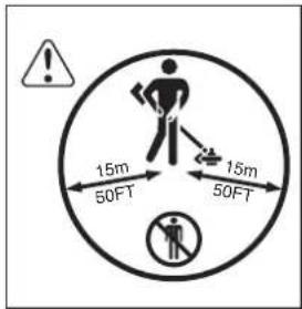
Keep all children, bystanders and helpers 15m away from the unit. If anyone approaches you, stop the engine and cutting attachment immediately.


It is important that you read, fully understand and observe the following safety precautions and warnings. Careless or improper use of the unit may cause serious or fatal injury.

Always wear eye, head and ear protectors when using this unit.
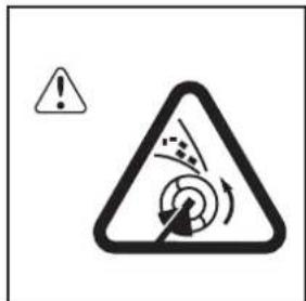
Be careful of thrown objects.

Shows maximum shaft speed. Do not use the cutting attachment whose max rpm is below the shaft rpm.

Gloves should be worn when necessary, e. g., when assembling cutting equipment.

Use anti-slip and sturdy footwear.

Indicates blade guard location for a trimmer head or Brain head.
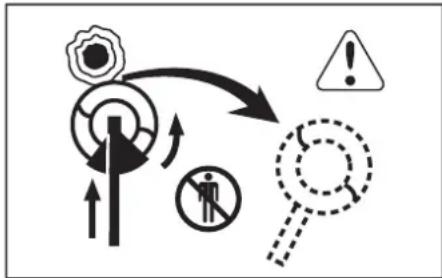
Blade thrust may occur when the spinning blade contacts a solid object in the critical area. A dangerous reaction may occur causing the entire unit and operator to be thrust violently. This reaction is called BLADE THRUST. As a result, the operator may lose control of the unit which may cause serious or fatal injury. Blade thrust is more likely to occur in areas where it is difficult to see the material to be cut.

Explains choke position. Upper sign indicates choke closed and the lower fully open.

Indicates handle location. Do not attach handle above this point.
WARNING!
- Read the Operator's Manual and follow all warnings and safety instructions. Failure to do so can result in serious injury to the operator and/or bystanders.
- Objects may be thrown or ricochet in all directions. ALWAYS WEAR EYE PROTECTION.
- Keep bystanders at least 50 feet (15m) away.
To reduce the chance of hearing loss, always wear ear protection.
To reduce the risk of injury from loss of control, never use a metal blade on a curved shaft grass trimmer. Never use a metal blade on any brushcutter without barrier bar or bicycle handle configuration and safety strap
- Use of a blade may cause a sudden sideways, forward or backward motion of the brushcutter when the blade contacts a solid object. See Owner's manual for model specific details.
Before using your machine
- Read the manual carefully.
- Check that the cutting equipment is correctly assembled and adjusted.
- Start the unit and check the carburetor adjustment. See "Maintenance".
We, Nikko Tanaka Engineering Co., Ltd., 3-4-29 Tsudanuma, Narashino, Chiba, Japan
Declare under our sole responsibility that the product, brushcutter model
TBC-500N TBC-550/DX TBC-600
to which this declaration relates is in conformity with the essential safety requirements of directives.
98/37/EC, 89/336/EEC, 2000/14/EC
The following standards have been taken into consideration
ISO 7112/7113/7916/7917/7918/8380/11682
(EN ISO 12100-1/2, EN ISO 11806)
Manufactured at: Chiba, Japan on the 05/01/2007
Signature: Y. L. O. N. S. Serial No. up from D088001
Position: Director
Index
What is what? 5
Warnings and safety instructions 6
Assembly procedures 7
Operating procedures 9
Maintenance 12
Specifications 14
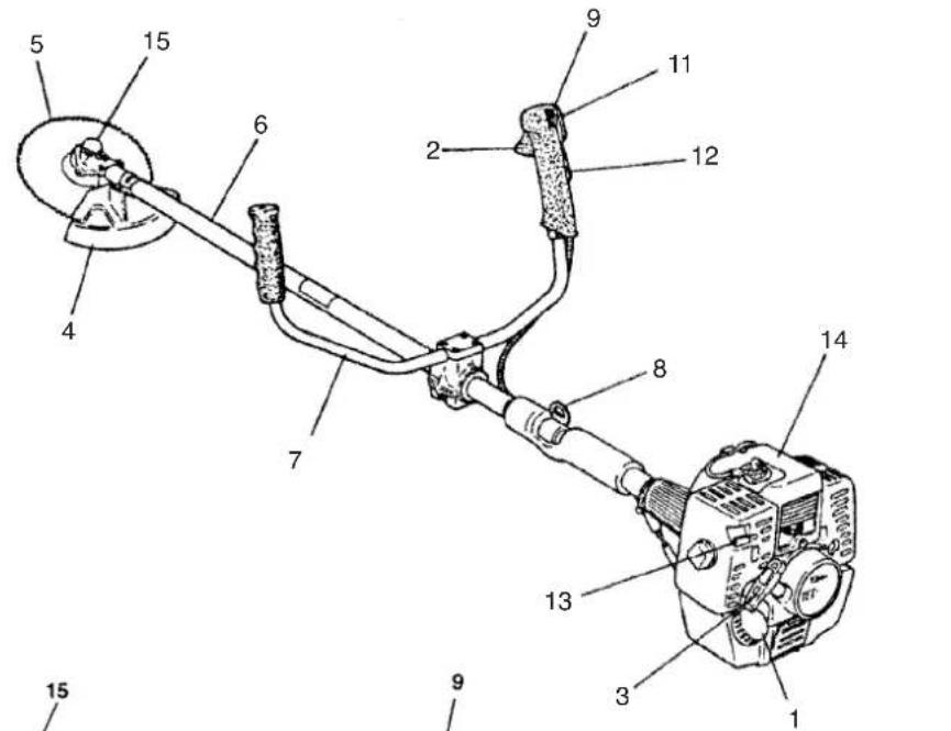
1. What is what?
Since this manual covers several models, there may be some difference between pictures and your unit. Use the instructions that apply to your unit.
- Fuel cap
- Throttle trigger
- Starter handle
- Blade guard
- Cutting attachment
6.Drive shaft tube
- Handle bar
- Suspension eyelet
- Ignition switch
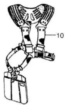
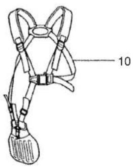
- Harness
- Throttle lock
- Throttle trigger lookout
- Choke lever
- Engine
- Angle transmission
TBC-500/550
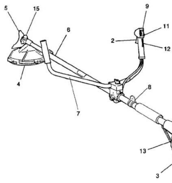
TBC-550DX
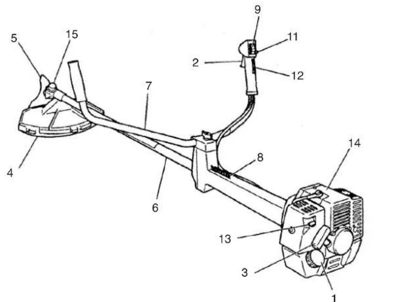
TBC-600
2.Warnings and safety instructions
Operator safety
Always wear a safety face shield or goggles.
Always wear heavy, long pants, boots and gloves. Do not wear loose clothing, jewelry, short pants, sandals or go barefoot. Secure hair so it is above shoulder length.
- Do not operate this tool when you are tired, ill or under the influence of alcohol, drugs or medication.
- Never let a child or inexperienced person operate the machine.
Wear hearing protection.
- Never start or run the engine inside a closed room or building. Breathing exhaust fumes can kill.
- Keep handles free of oil and fuel.
- Keep hands away from cutting equipment.
- Do not grab or hold the unit by the cutting equipment.
- When the unit is turned off, make sure the cutting attachment has stopped before the unit is set down.
- When operation is prolonged, take a break from time to time so that you may avoid possible whitefinger disease which is caused by vibration.
Unit / machine safety
- Inspect the entire unit/machine before each use. Replace damaged parts. Check for fuel leaks and make sure all fasteners are in place and securely tightened.
- Replace parts that are cracked, chipped or damaged in any way before using the unit/machine.
Make sure the safety guard is properly attached.
- Keep others away when making carburetor adjustments.
- Use only accessories as recommended for this unit/machine by the manufacturer.
WARNING!
Never modify the unit/machine in any way. Do not use your unit/machine for any job except that for which it is intended.
Fuel safety
WARNING!
Antivibration systems do not guarantee that you will not sustain whitefinger disease or carpal tunnel syndrome.
Cutting safety
- Do not cut any material other than grass and brush.
- Inspect the area to be cut before each use. Remove objects which can be thrown or become entangled.
- For respiratory protection, wear an aerosol protection mask when cutting the grass after insecticide is scattered.
- Keep others including children, animals, bystanders and helpers outside the 15m hazard zone. Stop the engine immediately if you are approached.
Always keep the engine on the right side of your body.
- Hold the unit/machine firmly with both hands.
- Keep firm footing and balance. Do not over-reach.
- Keep all parts of your body away from the muffler and cutting attachment when the engine is running.
- Keep cutting attachment below waist level.
Maintenance safety
- Maintain the unit/machine according to recommended procedures.
- Disconnect the spark plug before performing maintenance except for carburetor adjustments.
- Keep others away when making carburetor adjustments.
- Use only genuine Tanaka replacement parts as recommended by the manufacturer.
Transport and storage
- Carry the unit/machine by hand with the engine stopped and the muffler away from your body.
-Allow the engine to cool, empty the fuel tank, and secure the unit/machine before storing or transporting in a vehicle.
- Empty the fuel tank before storing the unit/machine, It is recommended that the fuel be emptied after each use. If fuel is left in the tank, store so fuel will not leak.
- Store unit/machine out of the reach of children.
Clean and maintenance the unit carefully and store it in a dry place
Make sure engine switch is off when transporting or storing.
- When transporting in a vehicle, cover blade with blade cover.
If situations occur which are not covered in this manual, take care and use common sense. Contact Tanaka dealer if you need assistance. Pay special attention to statements preceded by the following words:

WARNING!
Indicates a strong possibility of severe personal injury or loss of life, if instructions are not followed.
CAUTION!
Indicates a possibility of personal injury or equipment damage, if instructions are not followed.
NOTE!
Helpful information for correct function and use.
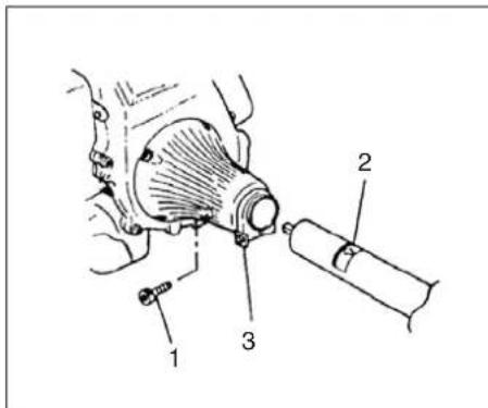
Fig. 1-1 Fig. 1-1B
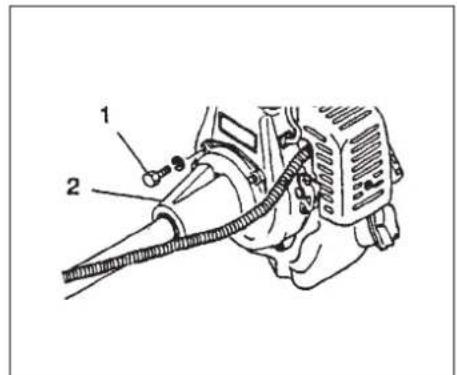

Fig. 1-2
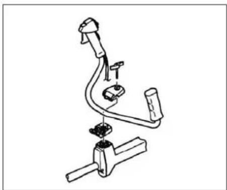
Fig. 1-2B
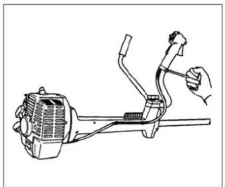
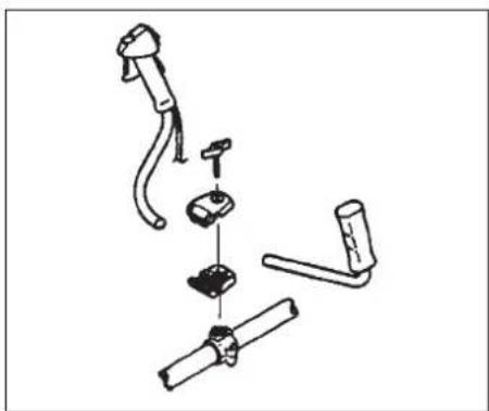
Fig. 1-2C Fig. 1-2D
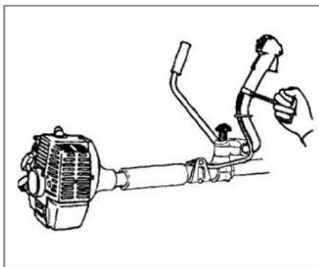
Fig. 1-2E
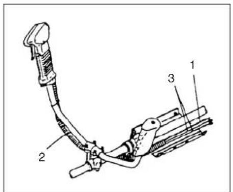
Fig. 1-3
3. Assembly procedures
Drive shaft to engine (Fig. 1-1)
Loosen tube locking bolt (1). Insert the drive shaft into the clutch case of the engine properly until the marked position (2) on the drive shaft tube meets the clutch case.
NOTE!
When it is hard to insert drive shaft up to the marked position on the drive shaft tube, turn drive shaft by the cutter mounting end clockwise or counter-clockwise. Tighten tube locking bolt lining up the hole in the shaft tube. Then tighten clamp bolt securely (3).
Drive shaft to engine for TBC-550DX (Fig.1 -1B)
Attach the engine to the clutch case (2) with the four screws or bolts (1) provided.
NOTE for TBC-600 (Fig. 1-2B, 2C)
The drive shaft and the engine of this model are pre-assembled at the factory. All you have to do is attach throttle grip on the handle with a screw and a nut and then, install it on the handle brackets. Finger-tighten the knob nut securely.
Installation of handle (Fig. 1-2)
Remove the handle bracket (1) from the assembly. (Fig. 1-2) Place the handles and attach the handle bracket with four bolts lightly. Adjust to appropriate position. Then fix it firmly with the bolts.
Installation handle for TBC-550DX
(Fig. 1-2D, 1-2E)
Place the handles and attach the handle bracket with the handle knob lightly. Adjust appropriate position. Then fix it firmly with the handle knob.
Attach throttle grip on the handle with a screw and nut.
Throttle wire/stop cord
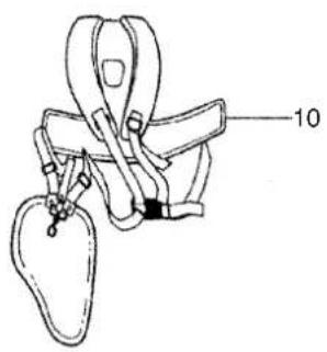
Put stop cords(3) and throttle wire(1) through protection tube(2). Then unhook the hip pad and wrap the protected stop cords and throttle wire (1) with it (Fig.1-3)
NOTE
Fix protection tube on drive shaft(TBC-550) or handle(TBC-550DX) using cord clamps.
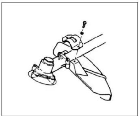
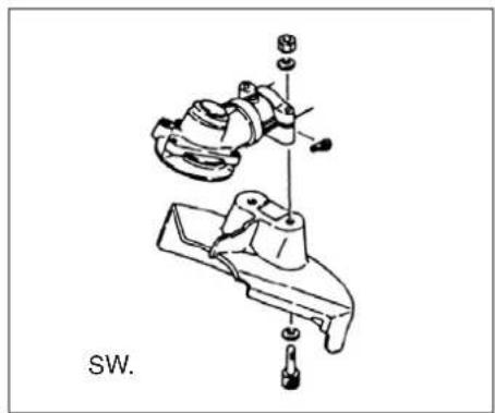
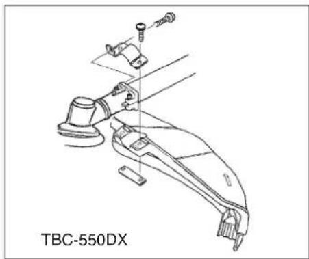
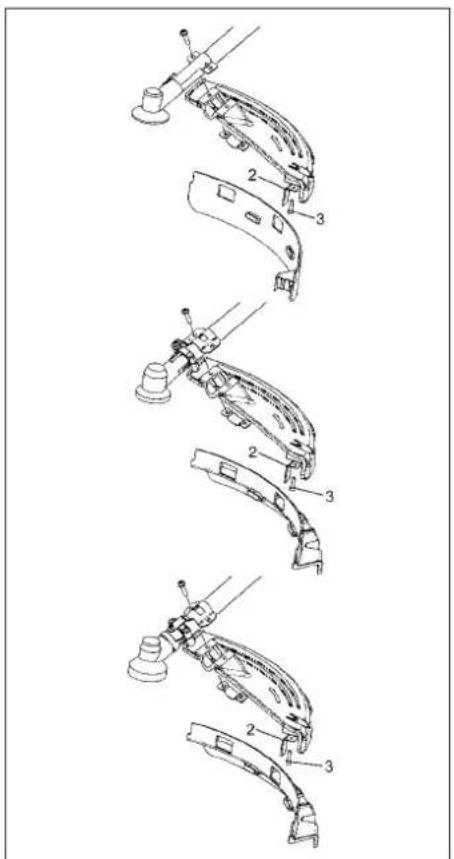
Fig. 1-8 Fig. 1-8DFig. 1-8B
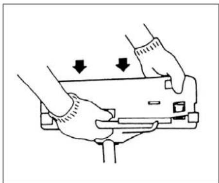
Fig. 1-9
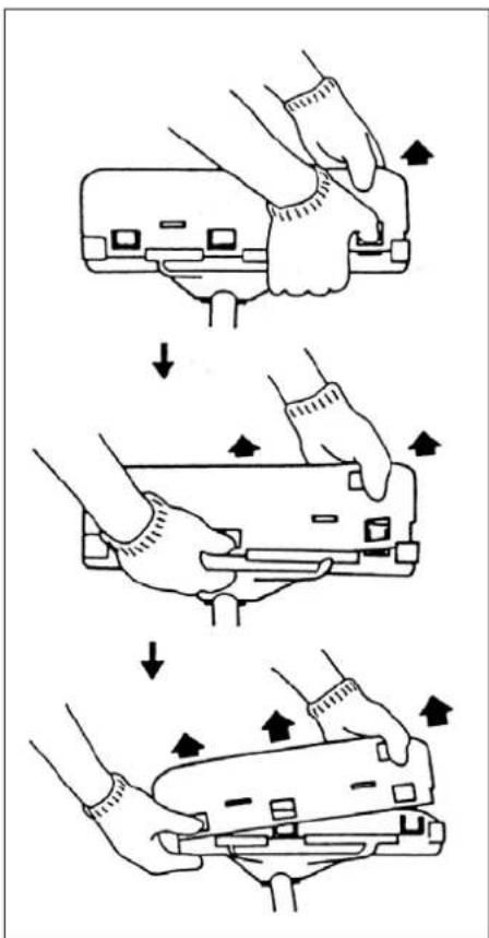
Fig. 1-9CFig. 1-8I
Installation of blade guard (Fig. 1-8, 8B, 8D, 8E)
NOTE!
The guard bracket may come already mounted to the gear case on some models.
Fix the guard bracket to the side the angle transmission (Fig. 1-8D).
Install the blade guard on drive shaft tube against angle transmission. Tighten the guard bracket firmly so that the blade guard does not swing or move down during operation.
CAUTION!
Some blade guards are equipped with sharp line limiters. Be careful with handling it.
NOTE! (Fig. 1-8E)
When using a Tanaka aluminum head (CH-100 or CH-300) on your unit, the sharp line limiter (2) which is included in the tool bag, should be securely fastened to the blade guard using the bolt shown (3).
When using a trimmer head with two piece type blade guard, attach the guard extension to the blade guard. (Fig. 1-9)
NOTE!
If your unit has guard location label on drive shaft tube, follow the indication.
NOTE!
When attaching the guard extension to the blade guard, the sharp line limiter must be removed from the blade guard, (if so installed).
NOTE!
To remove the guard extension, refer to the drawings. Wear gloves as the extension has a sharp line limiter, then push the four square tabs on the guard one by one in order. (Fig. 1-9C)
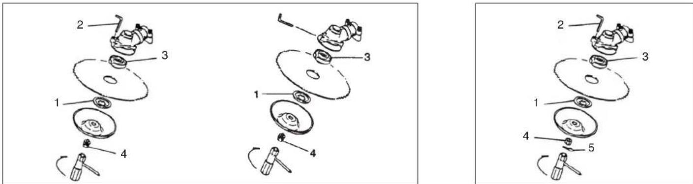
Fig. 1-10 Fig. 1-10B
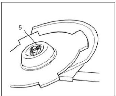
Fig. 1-10C
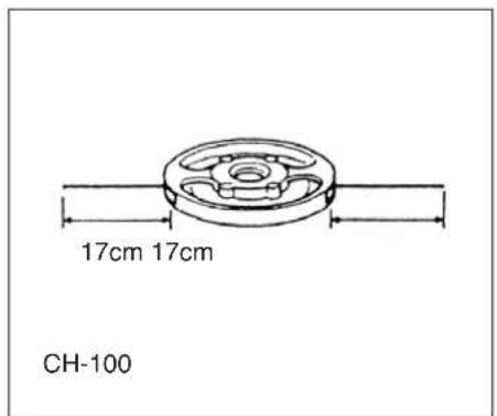
Fig. 1-11
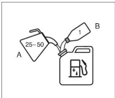
Fig.2-1
Installation of cutting blade (Fig.1-10,10B) (If so equipped)
When installing a cutting blade, make sure that there are no cracks or any damage in it and that the cutting edges are facing the correct direction.
NOTE!
When installing cutter holder cap (1), be sure to set concave side upward. Insert the allen wrench (2) into the hole of the angle transmission in order to lock the cutter holder (3). Please note that the cutter fixing bolt or nut (4) has left-handed threads, clockwise to loosen/counter-clockwise to tighten). Tighten the fixing bolt or nut with the box wrench.
NOTE!
If your unit is of a nut securing type and equipped with a cotter pin, the blade must be retained with a new cotter pin (5) each time installed. (Fig. 1-10C)
CAUTION!
Before operation, make sure the blade has been properly installed.
CAUTION!
If your unit is equipped with protection cover under a cutting blade, check it for wear or cracks before operation. If any damage or wear is found, replace it, as it is an article of consumption.
Installation of the BRAIN cutting head
NOTE!
For installation see your BRAIN Owner's manual, provided with the BRAIN cutting head.
WARNING!
For TANAKA BRAIN heads or TANAKA alloy head, use only flexible, non-metallic line recommended by the manufacturer. Never use wire or wire ropes. They can break off and become a dangerous projectile.
NOTE!
When using TANAKA alloy head (CH-100), initial cutting line length should be about 17cm each. (Fig. 1-11)
4. Operating procedures.
Fuel (Fig. 2-1)
WARNING!
The trimmer is equipped with a two-stroke engine. Always run the engine on fuel, which is mixed with oil. Provide good ventilation, when fueling or handling fuel.
Fuel
Always use branded 89 octane unleaded gasoline.
- Use genuine two-cycle oil or use a mix between 25:1 to 50:1, please consult the oil bottle for the ratio or Tanaka dealer.
-Only for the state of California at 50:1.
If genuine oil is not available, use an antioxidant added quality oil expressly labeled for air-cooled 2-cycle engine use(JASO FC GRADE OIL or ISO EGC GRADE). Do not use BIA or TCW (2-stroke water-cooling type) mixed oil.
- Never use multi-grade oil (10 W/30) or waste oil.
Always mix fuel and oil in a separate clean container.
Always start by filling half the amount of fuel, which is to be used. Then add the whole amount of oil. Mix (shake) the fuel mixture. Add the remaining amount of fuel. Mix (shake) the fuel-mix thoroughly before filling the fuel tank.
Fueling
WARNING!
Always shut off the engine before refueling.
- Slowly open the fuel tank, when filling up with fuel, so that possible over-pressure disappears.
- Tighten the fuel cap carefully, after fueling.
Always move the trimmer at least 3m (10 ft.) from the fueling area before starting.
Before fueling, clean the tank cap area carefully, to ensure that no dirt falls into the tank. Make sure that the fuel is well mixed by shaking the container, before fueling.
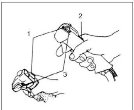
Fig.2-2
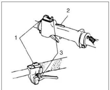
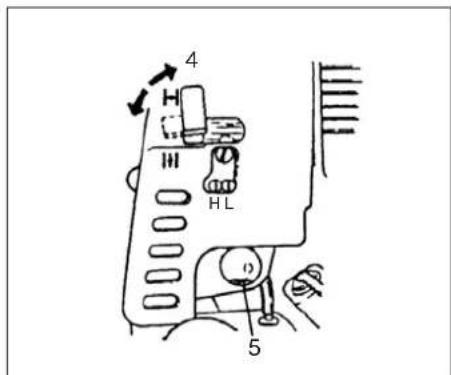
Fig.2-2B Fig.2-3
Starting (Fig. 2-2, 2B)
CAUTION!
Before starting, make sure the cutting attachment does not touch anything.
- Set ignition switch (1) to ON position. (Fig. 2-2, 2B)
*Push priming bulb (5) several times so that fuel flows through return pipe (If so equipped)(Fig. 2-3)
- With the safety trigger (2) pressed (if so equipped), pull throttle trigger and push throttle lock (3), then slowly release the throttle trigger first, then the safety trigger. This will lock the throttle in starting position. (Fig. 2-2, 2B)
- Set choke lever to CLOSED position (4). (Fig. 2-3)
- Pull recoil starter briskly, taking care to keep the handle in your grasp and not allowing it to snap back.
- When you hear the engine want to start, return choke lever to RUN position (open). Then pull recoil starter briskly again.
NOTE!
If engine does not start, repeat procedures from 2 to 5.
- After starting engine, pull throttle trigger to release throttle lock. Then allow the engine about 2-3 minutes to warm up before subjecting it to any load.

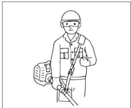
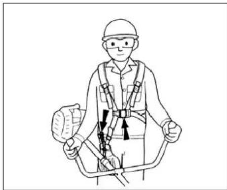
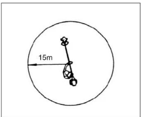
Fig. 2-4 Fig. 2-4B Fig. 2-4C
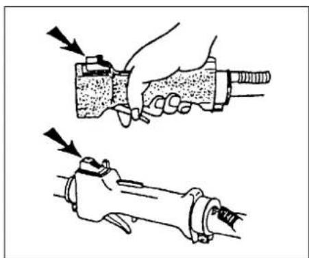
Fig. 2-4D Fig. 2-5
Cutting (Fig. 2-4, 4B, 4C, 4D)
- When cutting, operate engine at over 6500 rpm.
Extended time of use at low rpm may wear out the clutch prematurely.
Cut grass from right to left.
- Blade thrust may occur when the spinning blade contacts a solid object in the critical area. A dangerous reaction may occur causing the entire unit and operator to be thrust violently. This reaction is called BLADE THRUST. As a result, the operator may lose control of the unit which may cause serious or fatal injury. Blade thrust is more likely to occur in areas where it is difficult to see the material to be cut.
Wear the harness as shown in the figure (if so equipped). The blade turns counter-clockwise, therefore, be advised to operate the unit from right to left for efficient cutting. Keep onlookers out of working area at least 15 m (50 ft.).
NOTE!
Press the quick release button or pull emergency release flap (If so equipped) in the event of emergency. (Fig. 2-4C)
WARNING!
If cutting attachment should strike against stones or other debris, stop the engine and make sure that the attachment and related parts are undamaged. When grass or vines wrap around attachment, stop engine and attachment and remove them.
Stopping (Fig. 2-5)
Decrease engine speed and run at an idle for a few minutes, then turn off ignition switch.
WARNING!
A cutting attachment can injure while it continues to spin after the engine is stopped or power control is released.
When the unit is turned off, make sure the cutting attachment has stopped before the unit is set down.
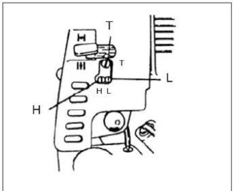
Fig.3-1
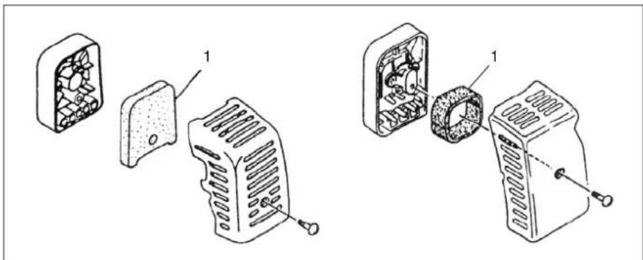
Fig. 3-2
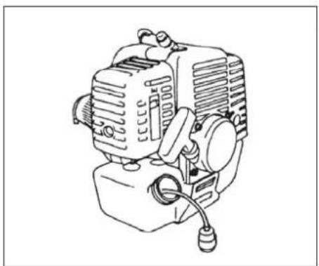
Fig. 3-2B
5. Maintenance
MAINTENANCE, REPLACEMENT, OR REPAIR OF THE EMISSION CONTROL DEVICES AND SYSTEMS MAY BE PERFORMED BY ANY NON-ROAD ENGINE REPAIR ESTABLISHMENT OR INDIVIDUAL.
Carburetor adjustment (Fig. 3-1)

WARNING!
The cutting attachment may be spinning during carburetor adjustments.

WARNING!
Never start the engine without the complete clutch cover and tube assembled! Otherwise the clutch can come loose and cause personal injuries.
In the carburetor, fuel is mixed with air. When the engine is test run at the factory, the carburetor is basically adjusted. A further adjustment may be required, according to climate and altitude. The carburetor has one adjustment possibility:
T = Idle speed adjustment screw.
Idle speed adjustment (T)
Check that the air filter is clean. When the idle speed is correct, the cutting attachment will not rotate. If adjustment is required, close (clockwise) the T-screw, with the engine running, until the cutting attachment starts to rotate. Open (counterclockwise) the screw until the cutting attachment stops. You have reached the correct idle speed when the engine runs smoothly in all positions well below the rpm when the cutting attachment starts to rotate.
If the cutting attachment still rotates after idle speed adjustment, contact Tanaka dealer.
NOTE!
Standard Idle rpm is 2500~3000 m ^-1 .
The standard openings (returns) of L/H screws from lightly seated positions are as follows.
| TBC-500 / 550 / 600 |
| L-SCREW | 1 1/8 |
| H-SCREW | 1 1/4 |

WARNING!
When the engine is Idling the cutting attachment must under no circumstances rotate.
NOTE!
Some models sold areas with strict exhaust emission regulation do not have high and low speed carburetor adjustments. Such adjustments may allow the engine to be operated outside of their emission compliance limits. For these models, the only carburetor adjustment is idle speed.
For models that equipped with low and high speed adjustments; carburetors are pre set at the factory Minor adjustments may optimize performance based on climate, altitude, etc. Never turn the adjustment screws in increments greater than 90 degrees, as engine damage can result from incorrect adjustment If you are not familiar with type of adjustment-assistance Tanaka dealer.
Air filter (Fig. 3-2)
The air filter must be cleaned from dust and dirt in order to avoid:
- Carburetor malfunctions.
Starting problems.
- Engine power reduction.
- Unnecessary wear on the engine parts.
Abnormal fuel consumption.
Clean the air filter daily or more often if working in exceptionally dusty areas.
Cleaning the air filter
Remove the air filter cover and the filter (1). Rinse it in warm soap suds. Check that the filter is dry before reassembly. An air filter that has been used for some time cannot be cleaned completely. Therefore, it must regularly be replaced with a new one. A damaged filter must always be replaced.
Fuel filter (Fig. 3-2B)
Drain all fuel from fuel tank and pull fuel filter line from tank. Pull filter element out of holder assembly and rinse element in warm water with detergent.
Rinse thoroughly until all traces of detergent are eliminated. Squeeze, do not wring, away excess water and allow element to air dry.
NOTE!
If element is hard due to excessive dirt buildup, replace it.
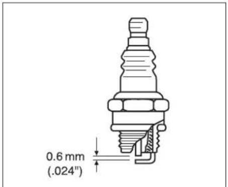
Fig.3-3
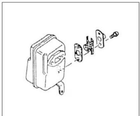
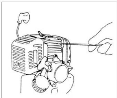
Fig.3-4 Fig.3-4B
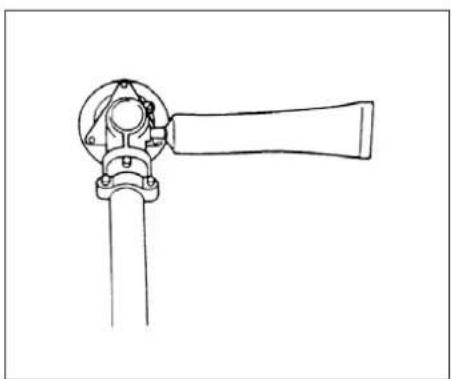
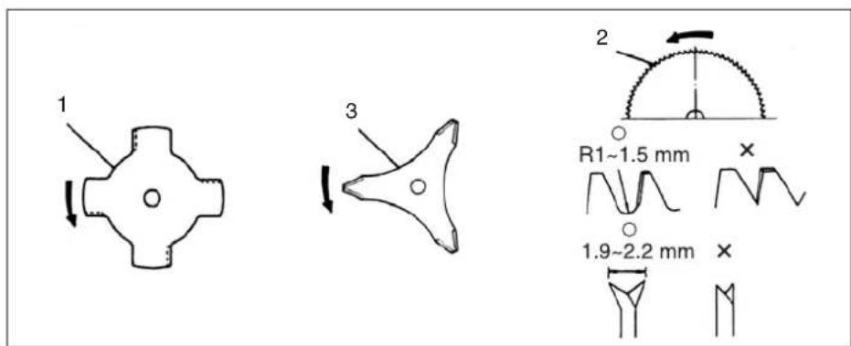
Fig.3-5 Fig.3-6
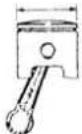
Spark plug (Fig. 3-3)
The spark plug condition is influenced by:
An incorrect carburetor setting.
- Wrong fuel mixture (too much oil in the gasoline)
- A dirty air filter.
- Hard running conditions (such as cold weather). These factors cause deposits on the spark plug electrodes, which may result in malfunction and starting difficulties. If the engine is low on power, difficult to start or runs poorly at idling speed, always check the spark plug first. If the spark plug is dirty, clean it and check the electrode gap.
Readjust if necessary. The correct gap is 0.6mm . The spark plug should be replaced after about 100 operation hours or earlier if the electrodes are badly eroded.
NOTE!
In some areas, local law requires using a resistor spark plug to suppress ignition signals. If this machine was originally equipped with resistor spark plug, use same type of spark plug for replacement.
Muffler (Fig. 3-4)
Remove the muffler and clean out any excess carbon from the exhaust port or muffler inlet every 100 hours of operation.
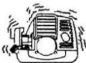
Cylinder (Engine cooling) (Fig. 3-4B)
The engine is air cooled, and air must circulate freely around engine and over cooling fins on cylinder head to prevent overheating.
Every 100 operating hours, or once a year, (more often if conditions require) clean fins and external surfaces of engine of dust, dirt and oil deposits which can contribute to improper cooling.
NOTE!
Do not operate engine with engine shroud or muffler guard removed as this will cause overheating and engine damage.
Angle transmission (Fig.3-5)
Check angle transmission or angle gear for grease level about every 50 hours of operation by removing the grease filler plug on the side of angle transmission.
If no grease can be seen on the flanks of the gears, fill the transmission with quality lithium based multipurpose grease up to 3/4. Do not completely fill the transmission.
Blade (Fig. 3-6)

WARNING!
Wear protective gloves when handling or performing maintenance on the blade.
- Use a sharp blade. A dull blade is more likely to snag and thrust. Replace the fastening nut if it is damaged and hard to tighten.
- When replacing blade, purchase one recommended by TANAKA, with a 25.4mm (one inch) fitting hole.
- When installing saw blade (2), always face the stamped side up. In the case of a 3 or 4 tooth blade (1, 3), it can be used on either side.
- Use correct blade for the type of work.
- When replacing blade, use appropriate tools.
- When cutting edges become dull, re-sharpen or file as shown in figure. Incorrect sharpening may cause excessive vibration.
- Discard blades that are bent, warped, cracked, broken or damaged in any way.
NOTE!
When sharpening blade it is important to maintain an original shape of radius at the base of the tooth to avoid cracking.
Maintenance schedule
Below you will find some general maintenance instructions. For further information please contact Tanaka dealer.
Daily maintenance
Clean the exterior of the unit.
- Check that the harness is undamaged.
- Check the blade guard for damage or cracks. Change the guard in case of impacts or cracks.
- Check that the cutting attachment is properly centred, sharp, and without cracks. An off-centred cutting attachment induces heavy vibrations that may damage the unit.
- Check that the cutting attachment nut is sufficiently tightened.
Make sure that the blade transport guard is undamaged and that it can be securely fitted.
- Check that nuts and screws are sufficiently tightened.
Weekly maintenance
Check the starter, especially cord and return spring.
Clean the exterior of the spark plug.
- Remove it and check the electrode gap. Adjust it to 0.6mm or change the spark plug.
Clean the cooling fins on the cylinder and check that the air intake at the starter is not clogged.
Check that the angle gear is filled with grease up to 3/4.
Clean the air filter.
Monthly maintenance
Rinse the fuel tank with gasoline.
Clean the exterior of the carburetor and the space around it.
Clean the fan and the space around it.
Spark arrester
If your unit comes with spark arrester screen and your local regulations require use of spark arrester for prevention against a possible fire, please attach it to the muffler by removing muffler protector and other related parts. [The spark arrester meets the regulation of SAE J335-SEP90 and CSA CAN3-Z62.1-M77]
6. Specifications
MODEL
Engine Size (mt)

Spark Plug

Fuel Tank Capacity (t)

Dry Weight (kg).

Sound pressure level (dB(A)) LpA
(EN 27917)

Sound power level (dB(A)) LwA
TBC-500/600 TBC-550/DX
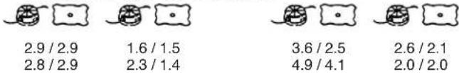
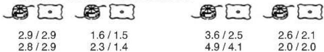
Vibration level (m / s^2) (ISO 7916)
Left handle.
Right handle.
47.0 (2.87 cu. in.)
NGK BPM-6A
or BPMR-6A
1.0 (33.8 fl. oz)
7.9 (17.4 lbs) / 8.7 (19.2 lbs) 8.7 (19.2 lbs) / 8.2 (18.1 lbs)
92.1/101.2 101.2/
TBC-500 TBC-550 116
TBC-600 116 TBC-550DX 116
TBC-500 TBC-5BBC-600 TBC-550DX
NOTE : Sound levels are calculated as the time-weighted energy total under various working conditions with the following time distribution:
1/2 idle, 1/2 racing.
- All data subject to change without notice.
Tanaka®
TBC-500
TBC-550/DX
TBC-600


7.9 (17.4 lbs) / 8.7 (19.2 lbs) 8.7 (19.2 lbs) / 8.2 (18.1 lbs)

Fare attenuation a oggetti lanciati a distance.

Do not attach handle above this point
7.9 (17.4 lbs) / 8.7 (19.2 lbs) 8.7 (19.2 lbs) / 8.2 (18.1 lbs)
92.1/101.2 101.2/
TBC-500 TBC-550 116
TBC-600 116 TBC-550DX 116
TBC-500 TBC-5BBC-600 TBC-550DX

2.9/2.9 1.6/1.5
2.8/2.9 2.3/1.4

3.6/2.5
4.9/4.1

2.6/2.1
2.0/2.0
Do not attach handle above this point
7.9 (17.4 lbs) / 8.7 (19.2 lbs) 8.7 (19.2 lbs) / 8.2 (18.1 lbs)
Gerauschpegel (dB(A)) LpA EN 27917

92.1/101.2 101.2/
7.9 (17.4 lbs) / 8.7 (19.2 lbs) 8.7 (19.2 lbs) / 8.2 (18.1 lbs)
92.1/101.2 101.2/
TBC-500 TBC-600 116
TBC-550 116
TBC-550DX 116
TBC-500 TBC-588C-600 TBC-550DX
Wij, Nikko Tanaka Engineering Co., Ltd., 3-4-29 Tsudanuma, Narashino, Chiba, Japan
Linker handgreep. Rechter handgreep
TBC-500/600 TBC-550/DX
47.0 (2.87 cu. in.)
NGK BPM-6A of BPMR-6A
1.0 (33.8 fl. oz)
7.9 (17.4 lbs) / 8.7 (19.2 lbs) 8.7 (19.2 lbs) / 8.2 (18.1 lbs)
92.1/101.2 101.2/
TBC-500 TBC-600 116
TBC-550 116
TBC-550DX 116
TBC-500 TBC-5BBC-600 TBC-550DX

2.9/2.9
2.8/2.9

1.6/1.5
2.3/1.4

3.6/2.5
4.9/4.1

2.6/2.1
2.0/2.0
7.9 (17.4 lbs) / 8.7 (19.2 lbs) 8.7 (19.2 lbs) / 8.2 (18.1 lbs)
92.1/101.2101.2/
TBC-500 TBC-550 116
TBC-600 116 TBC-550DX 116
TBC-500 TBC-588C-600 TBC-550DX

2.9/2.9 1.6/1.5
2.8/2.9 2.3/1.4

3.6/2.5 2.6/2.1
4.9/4.1 2.0/2.0
7.9 (17.4 lbs) / 8.7 (19.2 lbs) 8.7 (19.2 lbs) / 8.2 (18.1 lbs)
92.1/101.2 101.2/
TBC-500 TBC-550 116
TBC-600 116 TBC-550DX 116
2.9/2.9 1.6/1.5 3.6/2.5 2.6/2.1
2.8/2.9 2.3/1.4 4.9/4.1 2.0/2.0
SHMEIOH: Ta 10oobvapa enineda uouc oopbou/odvno n cival unoloyioeva ng n staumieyn oTo xpovo uovolki evepyia yia ta eine da bopou/odvno n ckat ano diapopetikc ouvntknc spyaiaac me tvn akolouon katavoum tou xpvou:
Nikko Tanaka Engineering Co., Ltd.