
6992D - Screwdriver MAKITA - Free user manual and instructions
Find the device manual for free 6992D MAKITA in PDF.
| Product type | Cordless screwdriver |
| Brand | Makita |
| Model | 6992D |
| Standard bolt capacity | M8 – M14 |
| High strength bolt capacity | M6 – M10 |
| Square bit | 12,7 mm |
| No load speed | 0 – 2 300 min⁻¹ |
| Impacts per minute | 0 – 3 000 min⁻¹ |
| Max tightening torque | 100 N·m |
| Overall length | 176 mm |
| Net weight (with battery) | 1,4 kg |
| Rated voltage | 9.6 V DC |
| Battery type | Makita rechargeable battery (models 9122, 9133, 9134, 9135) |
| Charger | DC1411 |
| Typical charging time | 60 to 90 minutes depending on capacity |
| Charging temperature range | 10 °C to 40 °C |
| Main functions | Reverse switch, variable speed trigger, automatic stop |
| Safety | Reverse switch in neutral locks trigger, overload and overheat protection |
| Maintenance | Replace carbon brushes when wear mark is reached, regular cleaning |
| Included accessories | Socket with O-ring and rod |
Frequently Asked Questions - 6992D MAKITA
User questions about 6992D MAKITA
0 question about this device. Answer the ones you know or ask your own.
Ask a new question about this device
Download the instructions for your Screwdriver in PDF format for free! Find your manual 6992D - MAKITA and take your electronic device back in hand. On this page are published all the documents necessary for the use of your device. 6992D by MAKITA.
USER MANUAL 6992D MAKITA
GB Cordless Impact Wrench Instruction Manual
natural_image
Line drawing of a Tokalda electric drill press with attached battery pack (no text or symbols)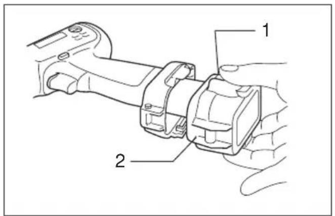
1
2
3
4
5
6
line
| N·m (kgf·cm) | M10 | M12 | M14 | | ------------ | ------- | ------- | ------- | | 15 | 204 | 408 | 612 | | 16 | - | - | - |7
GB Standard bolt
F Boulon standard
D Standardschrauben
I Bullone standard
NL Standaard bout
E Tornillo estándar
P Porca normal
DK Standardbolt
s Standardbult
N Standardbolt
SF Nornaali pultti
GR Kavovikó μπουλόνι
line
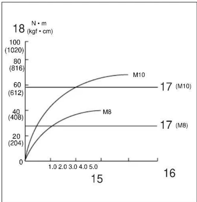
| x | M8 | M10 | M17 | | ---- | ------ | ------ | ------ | | 0 | 0 | 0 | 0 | | 1.0 | ~204 | ~408 | 612 | | 2.0 | ~308 | ~556 | 612 | | 3.0 | ~356 | ~652 | 612 | | 4.0 | ~408 | ~724 | 612 | | 5.0 | ~456 | ~788 | 612 | | 15 | ~408 | ~816 | 612 | | 16 | ~356 | ~816 | 612 |8
GB High tensile bolt
F Boulon à haute résistance
D HV-Schrauben
I Bullone altamente tensile
NL Bout met grote treksterkte
E Tornillo de alta resistencia
P Porca de grande elasticidade
DK Kvalitetsstålbolt
s Bult med hög hållfasthet
N Høy strekkbolt
SF Suurvetolujuuspultti
GR Μπουλόνι υψηλής εκτατικότητος
9
10
11
ENGLISH
| 1 Push button | 9 Switch trigger | 17 Proper fastening torque for |
| 2 Battery cartridge | 10 Reversing switch lever | 18 Fastening torque |
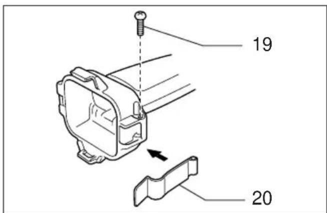
| 3 Charging light | 11 A side | 19 Screw |
| 4 Fast charger | 12 B side | 20 Set plate |
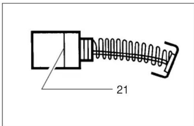
| 5 Socket | 13 Clockwise | 21 Limit mark |
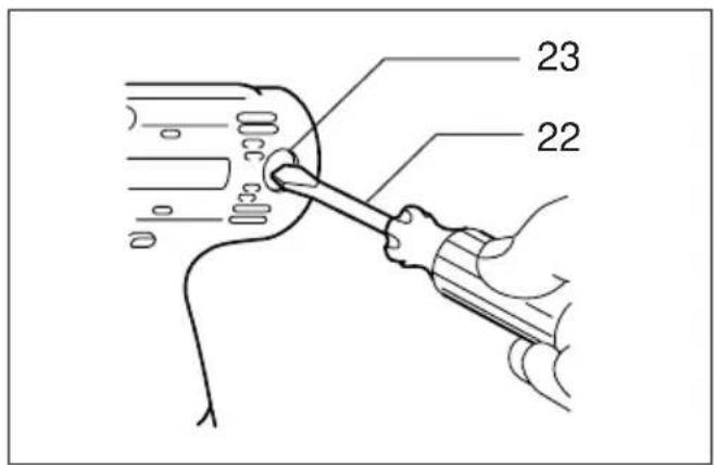
| 6 Anvil | 14 Counterclockwise | 22 Screwdriver |
| 7 Pin | 15 Fastening time | 23 Brush holder cap |
| 8 O-ring | 16 Seconds |
SPECIFICATIONS
Model 6991D 6992D
| Capacities | |
| Standard bolt | M8 — M14 M8 — M14 |
| High tensile bolt | M6 — M10 M6 — M10 |
| Square drive | 9.5 mm 12.7 mm |
| No load speed (mirl) | 0 — 2,300 0 — 2,300 |
| Impacts per minute | 0 — 3,000 0 — 3,000 |
| Max. fastening torque | 100 .M 100 N ·m |
| Overall length | 168 mm 176 mm |
| Net weight (with battery cartridge) | 1.3 kg 1.4 kg |
| Rated voltage | D.C. 9.6 V D.C. 9.6 V |
- Due to our continuing program of research and development, the specifications herein are subject to change without notice.
- Note: Specifications may differ from country to country.
Safety Hints
For your own safety, please refer to the enclosed safety instructions.
IMPORTANT SAFETY INSTRUCTIONS FOR CHARGER & BATTERY CARTRIDGE
ENC001-2
-
SAVE THESE INSTRUCTIONS — This manual contains important safety and operating instructions for battery charger.
-
Before using battery charger, read all instructions and cautionary markings on (1) battery charger, (2) battery, and (3) product using battery.
-
CAUTION — To reduce risk of injury, charge only MAKITA type rechargeable batteries. Other types of batteries may burst causing personal injury and damage.
-
Do not expose charger to rain or snow.
-
Use of an attachment not recommended or sold by the battery charger manufacturer may result in a risk of fire, electric shock, or injury to persons.
-
To reduce risk of damage to electric plug and cord, pull by plug rather than cord when dis-3-connecting charger.
-
Make sure cord is located so that it will not be stepped on, tripped over, or otherwise subjected to damage or stress.
-
Do not operate charger with damaged cord o5 plug — replace them immediately.
-
Do not operate charger if it has received a sharp blow, been dropped, or otherwise damaged in any way; take it to a qualified serviceman.
- Do not disassemble charger or battery cartridge; take it to a qualified serviceman when service or repair is required. Incorrect reassembly may result in a risk of electric shock or fire.
- To reduce risk of electric shock, unplug charger from outlet before attempting any maintenance or cleaning. Turning off controls will not reduce this risk.
- The battery charger is not intended for use by young children or infirm persons without supervision.
- Young children should be supervised to ensure that they do not play with the battery charger.
ADDITIONAL SAFETY RULES FOR CHARGER & BATTERY CARTRIDGE
-
Do not charge battery cartridge when temperature is BELOW 10^ C ( 50^ F) or ABOVE 40^ C ( 104^ F).
-
Do not attempt to use a step-up transformer, an engine generator or DC power receptacle.
- Do not allow anything to cover or clog the charger vents.
4be Always cover the battery terminals with the battery cover when the battery cartridge is not used.
Do not short the battery cartridge: (1) Do not touch the terminals with any conductive material.
(2) Avoid storing battery cartridge in a container with other metal objects such as nails, coins, etc.
(3) Do not expose battery cartridge to water rain.
A battery short can cause a large current flow overheating, possible burns and even a breakdown.
- Do not store the tool and battery cartridge in locations where the temperature may reach or exceed 50°C (122°F).
- Do not incinerate the battery cartridge even if it is severely damaged or is completely worn out. The battery cartridge can explode in a fil
- Be careful not to drop, shake or strike battery
- Do not charge inside a box or container of a kind. The battery must be placed in a well ventilated area during charging.
ADDITIONAL SAFETY RULES FOR TOOL
ENB025-1
- Be aware that this tool is always in an operating condition, because it does not have to be plugged into an electrical outlet.
- Hold tool by insulated gripping surfaces when performing an operation where the cutting too
may contact hidden wiring. Contact with a "live" wire will also make exposed metal p of the tool "live" and shock the operator.
- Wear ear protectors.
- Check the socket carefully for wear, cracks or damage before installation.
5r Hold the tool firmly.
- Always be sure you have a firm footing.
Be sure no one is below when using the tool in high locations. - The proper fastening torque may differ depending upon the kind or size of the bolt. Check the torque with a torque wrench.
SAVE THESE INSTRUCTIONS.
OPERATING INSTRUCTIONS
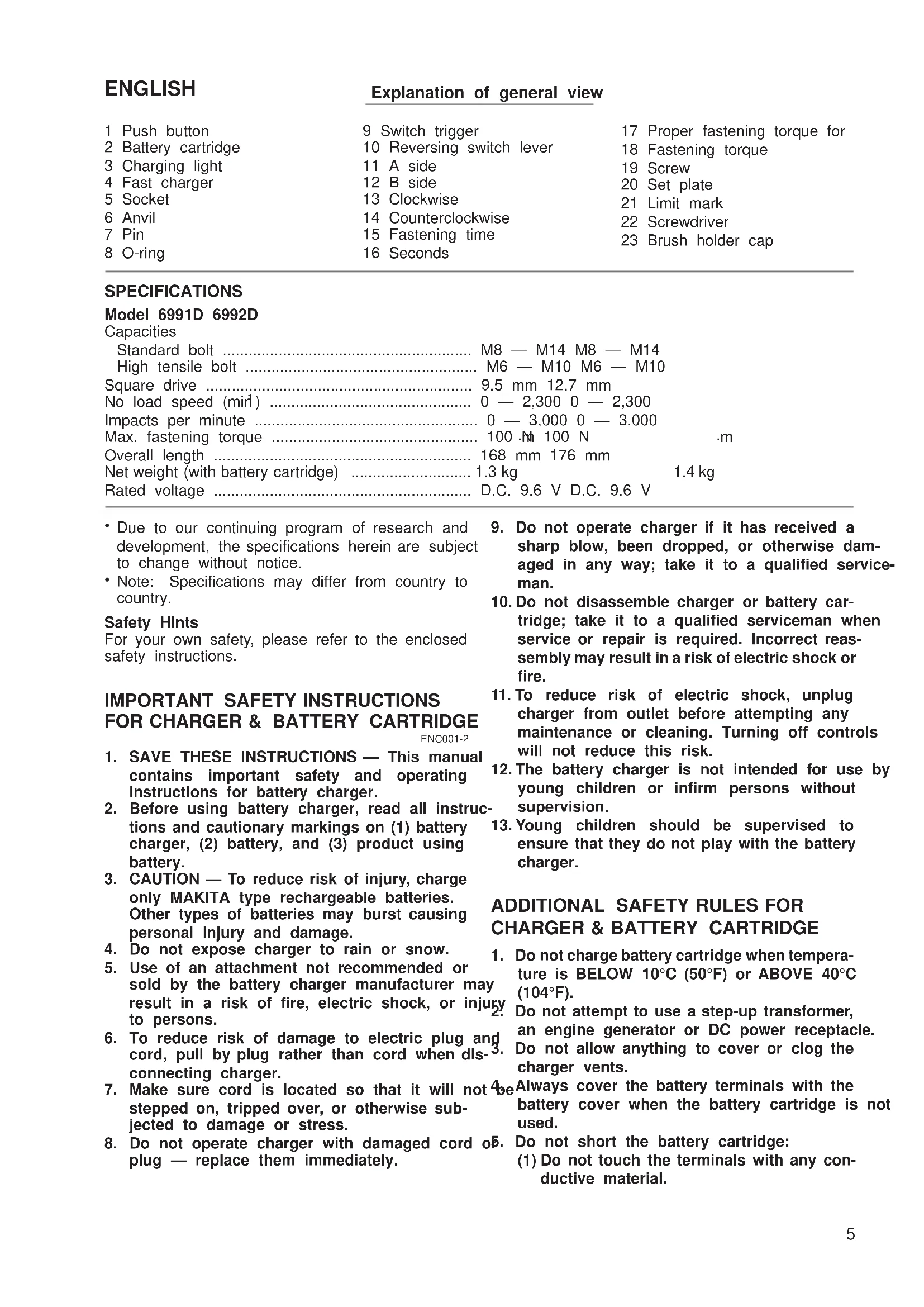
ryInstalling or removing battery cartridge and (Fig. 1)
• Always switch off the tool before insertion or removal of the battery cartridge.
- To remove the battery cartridge, withdraw it from the tool while pressing the push buttons on both sides of the cartridge.
- To insert the battery cartridge, align the tongue on at-the battery cartridge with the groove in the housing e and slip it into place. Always insert it all the way until it locks in place with a little click. If not, it may n accidentally fall out of the tool, causing injury to you ol or someone around you.
- Do not use force when inserting the battery cartridge. If the cartridge does not slide in easily, it is not being inserted correctly.
Charging (Fig. 2)
Your new battery cartridge is not charged. You will need to charge it before use. Use the battery charger Mo DC1411 to charge the battery cartridge.
Plug the battery charger into the proper A/C voltage source. The charging light will flash in green color. Insert the battery cartridge so that the plus and minus terminals on the battery cartridge are on the same sides as respective markings on the battery charger. Insert the cartridge fully into the port so that it rests on the charge port floor. When the battery cartridge is inserted, the charging light color will change from green to red and charging will begin. The charging light will remain lit steadily during charging. When the charging light color changes from red to green, the charging cycle is complete.
If you leave the battery cartridge in the charger after the charging cycle is complete, the charger will switch in its “trickle charge (maintenance charge)” mode which will last approximately 24 hours. After charging, unplug the charger from the power source. Refer to the table below for the charging time.
| Battery type Capacity (mAh) Number of cells | Charging time | ||
| 9122 | 2,000 | 8 | Approx. 60 min. |
| 9133 | 2,200 | 8 | Approx. 65 min. |
| 9134 | 2,600 | 8 | Approx. 75 min. |
| 9135 | 3,000 | 8 | Approx. 90 min. |
CAUTION:
- The battery charger Model DC1411 is for charging Makita battery cartridge. Never use it for other purposes or for other manufacturer's batteries.
- When you charge a new battery cartridge or a battery cartridge which has not been used for a long period time, it may not accept a full charge. This is a normal condition and does not indicate a problem. You can recharge the battery cartridge fully after discharging it completely and recharging a couple of times.
- If you charge a battery cartridge from a just-operated tool or a battery cartridge which has been left in a location exposed to direct sunlight or heat for a long time, the charging light may flash in red color. If this occurs, wait for a while. Charging will begin after the battery cartridge cools. The battery cartridge will cool faster if you remove the battery cartridge from the battery charger.
- If the charging light flashes alternately in green and red color, a problem exists and charging is not po: The terminals on the charger or battery cartridge are clogged with dust or the battery cartridge is worn damaged.
Trickle charge (Maintenance charge)
If you leave the battery cartridge in the charger to prevent spontaneous discharging after full charge, the charger will switch into its “trickle charge (maintenance charge)” mode and keep the battery cartridge fres fully charged.
Tips for maintaining maximum battery life
- Charge the battery cartridge before completely discharged.
Always stop tool operation and charge the battery cartridge when you notice less tool power.
- Never recharge a fully charged battery cartridge.
Overcharging shortens the battery service life.
- Charge the battery cartridge with room temperature at 10°C - 40°C (50°F - 104°F).
Let a hot battery cartridge cool down before charging it.
- Charge the Nickel Metal Hydride battery cartridge when you do not use it for more than six months.
Selecting correct socket
Always use the correct size socket for bolts and nut. An incorrect size socket will result in inaccurate and inconsistent fastening torque and/or damage to the bolt or nut.
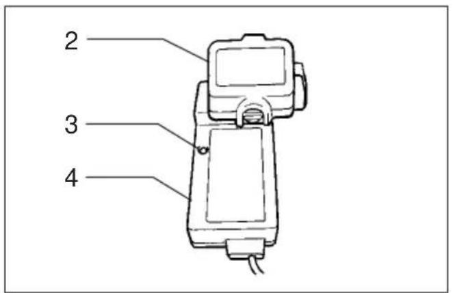
Installing or removing socket (Fig. 3 & 4)
CAUTION:
Always be sure that the tool is switched off and the battery cartridge is removed before installing or removing the socket.
1. For socket without O-ring and pin (Model 6991D & 6992D)
To install the socket, push it onto the anvil of tool until it locks into place.
To remove the socket, simply pull it off.
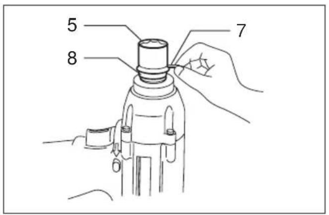
2. For socket with O-ring and pin (Model 6992D)
Move the O-ring out of the groove in the socket and remove the pin from the socket. Fit the socket onto the anvil of the tool so that the hole in the socket is aligned with the hole in the anvil. Inse
the pin through the hole in the socket and anvilHold the tool firmly and place the socket over the bol Then return the O-ring to the original position inor nut. Turn the tool on and fasten for the proper the socket groove to retain the pin. To remove fastening time.
socket, follow the installation procedures in reverse.
Switch action (Fig. 5)
CAUTION:
Before inserting the battery cartridge into the tool, always check to see that the switch trigger actuates properly and returns to the "OFF" position when released.
To start the tool, simply pull the trigger. Tool speed increased by increasing pressure on the trigger.
Release the trigger to stop.
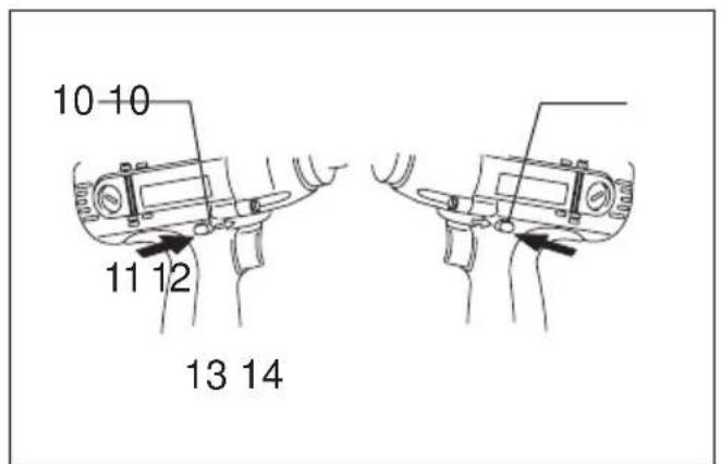
Reversing switch action (Fig. 6)
tsCAUTION:
Always check the direction of rotation before operation.
- Use the reversing switch only after the tool comes to a complete stop. Changing the direction of rotation before the tool stops may damage the tool.
- When not operating the tool, always set the reversing switch lever to the neutral position.
This tool has a reversing switch to change the direction of rotation. Depress the reversing switch lever from the A side for clockwise rotation or from the B side for counterclockwise rotation. When the switch lever is in the neutral position, the switch trigger cannot be pulled.
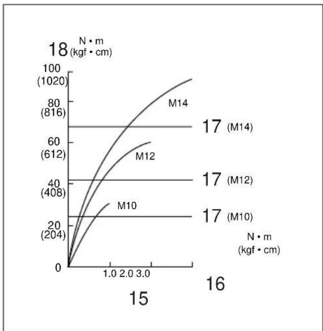
Operation (Fig. 7 & 8)
The proper fastening torque may differ depending upon the kind or size of the bolt. The relation between fastening torque and fastening time is shown in the figures.
IHold the tool firmly and place the socket over the bol nor nut. Turn the tool on and fasten for the proper fastening time.
NOTE:
- Hold the tool pointed straight at the bolt or nut without applying excessive pressure on the tool.
- Excessive fastening torque may damage the bolt or nut. Before starting your job, always perform a test operation to verify the adequate fastening speed and time for your bolt or nut.
The fastening torque is affected by a wide variety of factors including the following. After fastening, always check the torque with a torque wrench.
- When the battery cartridge is discharged almost completely, voltage will drop and the fastening torque will be reduced.
2. Socket
- Failure to use the correct size socket will cause a reduction in the fastening torque.
- A worn socket (wear on the hex end or square end) will cause a reduction in the fastening torque.
3. Bolt
MAINTENANCE
- Even though the torque coefficient and the c of bolt are the same, the proper fastening to will differ according to the diameter of the b
- Even though the diameters of bolts are the same, the proper fastening torque will differ according to the torque coefficient, the class bolt and the bolt length.
- The use of the universal joint or the extension somewhat reduces the fastening force of the impact wrench. Compensate by fastening for a longer period of time.
- Type of materials to be fastened, the manner of holding the tool and the tool speed will affect the torque.
CAUTION:
If the tool is operated continuously until the battery cartridge has discharged, allow the tool to rest for 15 minutes before proceeding with a fresh battery.
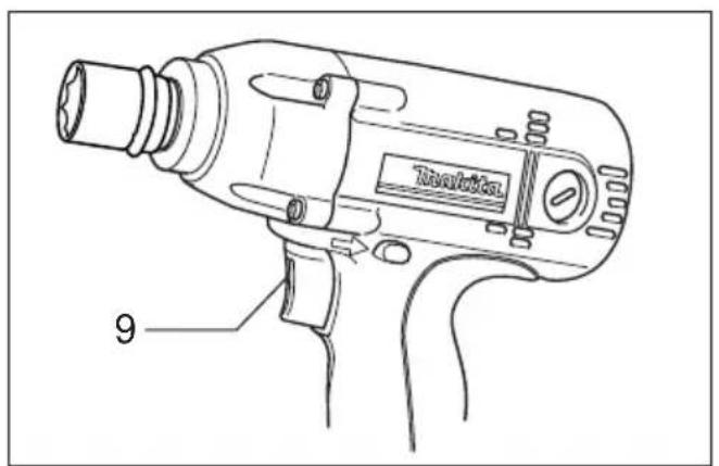
Installing set plate (Optional accessory)
(Fig. 9)
Always install the set plate when using battery cartridges 9100, 9102 or 9102A. Install the set plate on the tool with the screw provided.
ass CAUTION:
Always be sure that the tool is switched off and the battery cartridge is removed before carrying out any work on the tool.
Replacement of carbon brushes (Fig. 10 & 11)
Replace carbon brushes when they are worn down to the limit mark. Both identical carbon brushes should be replaced at the same time.
To maintain product safety and reliability, repairs, maintenance or adjustment should be carried out by a Makita Authorized Service Center.
FRANÇAIS
Descriptif
Reversbryter (Fig. 6)
NB!
These accessories or attachments are recommended for use with your Makita tool specified in this manual use of any other accessories or attachments might present a risk of injury to persons. The accessories of attachments should be used only in the proper and intended manner.
F ACCESSOIRES
ATTENTION :
- Use bit No. 2 when fastening machine screws M4 – M5, or wood screws 3.1 mm – 4.8 mm.
- Use bit No. 3 when fastening machine screws M6 – M8, or wood screws 5.1 mm – 6.1 mm.
Note :

- Safety Hints
- IMPORTANT SAFETY INSTRUCTIONS FOR CHARGER & BATTERY CARTRIDGE
- ENC001-2
- ADDITIONAL SAFETY RULES FOR CHARGER & BATTERY CARTRIDGE
- ADDITIONAL SAFETY RULES FOR TOOL
- SAVE THESE INSTRUCTIONS.
- OPERATING INSTRUCTIONS
- ryInstalling or removing battery cartridge and (Fig. 1)
- Charging (Fig. 2)
- CAUTION:
- Trickle charge (Maintenance charge)
- Tips for maintaining maximum battery life
- Selecting correct socket
- Installing or removing socket (Fig. 3 & 4)
- For socket without O-ring and pin (Model 6991D & 6992D)
- For socket with O-ring and pin (Model 6992D)
- Switch action (Fig. 5)
- Reversing switch action (Fig. 6)
- Operation (Fig. 7 & 8)
- NOTE:
- Socket
- Bolt
- MAINTENANCE
- Installing set plate (Optional accessory)
- (Fig. 9)
- Replacement of carbon brushes (Fig. 10 & 11)
- Reversbryter (Fig. 6)
- F ACCESSOIRES
- ATTENTION :
- Note :
Brand : MAKITA
Model : 6992D
Category : Screwdriver