
BTW150 - Screwdriver MAKITA - Free user manual and instructions
Find the device manual for free BTW150 MAKITA in PDF.

| Brand | Makita |
| Model | BTW150 |
| Product type | Cordless Impact Driver |
| Rated voltage | 14.4 V DC |
| Screwing capacity (standard bolt) | 10 mm – 16 mm |
| Screwing capacity (high-strength bolt) | 8 mm – 12 mm |
| Drive | Square for socket |
| Cooling system | Built-in fan |
| Compatible battery type | Makita rechargeable battery (Li-ion / Ni-MH) |
| Charging time (battery BH1420 2 Ah) | Approximately 30 min |
| Charging time (battery BH1433 3.3 Ah) | Approximately 50 min |
| Charging temperature range | 10 °C – 40 °C |
| Rotation direction switch | Yes (3 positions: right, left, neutral) |
| Charge indicators | Two LEDs (green/red) |
| Overload protection | Yes (flashing charge indicator) |
| Compensation charge function (maintenance) | Yes (after full charge) |
| Cooling fan | Yes |
| Brush wear indicator | Yes |
| Maintenance | Replaceable brushes (pair) |
| Drive pin | Yes |
| Safety | Trigger lock in neutral position |
Frequently Asked Questions - BTW150 MAKITA
User questions about BTW150 MAKITA
0 question about this device. Answer the ones you know or ask your own.
Ask a new question about this device
Download the instructions for your Screwdriver in PDF format for free! Find your manual BTW150 - MAKITA and take your electronic device back in hand. On this page are published all the documents necessary for the use of your device. BTW150 by MAKITA.
USER MANUAL BTW150 MAKITA
natural_image
Line drawing of a handheld electric drill putter with control panel and base (no text or symbols)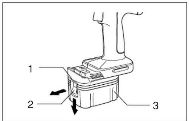
1
2
3
4
5
6
line
| M | N·m (kgf·cm) | | ---- | ------------ | | M12 | 816 | | M14 | 1020 | | M16 | 1224 | | 19 | 1428 |7
line
| Series | X Value | Y Value | |--------|---------|-------------| | M8 | 0.0 | 30 | | M8 | 1.0 | 408 | | M8 | 2.0 | 500 | | M8 | 3.0 | 600 | | M8 | 4.0 | 700 | | M8 | 5.0 | 816 | | M10 | 0.0 | 408 | | M10 | 1.0 | 600 | | M10 | 2.0 | 750 | | M10 | 3.0 | 900 | | M10 | 4.0 | 1050 | | M10 | 5.0 | 1200 | | M12 | 0.0 | 204 | | M12 | 1.0 | 408 | | M12 | 2.0 | 600 | | M12 | 3.0 | 800 | | M12 | 4.0 | 1000 | | M12 | 5.0 | 1224 | | M12 | 6.0 | 1428 | | M12 | 7.0 | 1632 | | M12 | 8.0 | 1848 | | M12 | 9.0 | 2074 | | M12 | 10.0 | 2300 | | M12 | 11.0 | 2536 | | M12 | 12.0 | 2772 | | M12 | 13.0 | 3018 | | M12 | 14.0 | 3274 | | M12 | 15.0 | 3538 | | M12 | 16.0 | 3804 | | M12 | 17.0 | 4078 | | M12 | 18.0 | 4354 | | M12 | 19.0 | 4638 | | M12 | 20.0 | 4924 | | M12 | 21.0 | 5218 | | M12 | 22.0 | 5514 | | M12 | 23.0 | 5818 | | M12 | 24.0 | 6114 | | M12 | 25.0 | 6408 | | M12 | 26.0 | 6704 | | M12 | 27.0 | 7008 | | M12 | 28.0 | 7314 | | M12 | 29.0 | 7618 | | M12 | 30.0 | 7924 | | M12 | 31.0 | 8228 | | M12 | 32.0 | 8534 | | M12 | 33.0 | 8848 | | M12 | 34.0 | 9164 | | M12 | 35.0 | 9488 | | M12 | 36.0 | 9814 | | M12 | 37.0 | 10138 | | M12 | 38.0 | 10474 | | M12 | 39.0 | 10814 | | M12 | 40.0 | 11156 | | M12 | 41.0 | 11508 | | M12 | 42.0 | 11876 | | M12 | 43.0 | 12248 | | M12 | 44.0 | 12632 | | M12 | 45.0 | 13024 | | M12 | 46.0 | 13428 | | M12 | 47.0 | 13836 | | M12 | 48.0 | 14248 | | M12 | 49.0 | 14664 | | M12 | 50.0 | 15088 | | M12 | 51.0 | 15516 | | M12 | 52.0 | 15944 | | M12 | 53.0 | 16388 | | M12 | 54.0 | 16836 | | M12 | 55.0 | 17294 | | M12 | 56.0 | 17756 | | M12 | 57.0 | 18216 | | M12 | 58.0 | 18676 | | M12 | 59.0 | 19138 | | M12 | 60.0 | 19596 | | M12 | 61.0 | 20068 | | M12 | 62.0 | 20548 | | M12 | 63.0 | 21038 | | M12 | 64.0 | 21536 | | M12 | 65.0 | 22036 | | M12 | 66.0 | 22536 | | M12 | 67.0 | 23036 | | M12 | 68.0 | 23536 | | M12 | 69.0 | 24036 | | M12 | 70.0 | 24536 | | M12 | 71.0 | 25036 | | M12 | 72.0 | 25536 | | M12 | 73.0 | 26036 | | M12 | 74.0 | 26536 | | M12 | 75.0 | 27036 | | M12 | 76.0 | 27536 | | M12 | 77.0 | 28036 | | M12 | 78.0 | 28536 | | M12 | 79.0 | 29036 | | M12 | 80.0 | 29536 | | M12 | 81.0 | 30036 | | M12 | 82.0 | 30536 | | M12 | 83.0 | 31036 | | M12 | 84.0 | 31536 | | M12 | 85.0 | 32036 | | M12 | 86.0 | 32536 | | M12 | 87.0 | 33036 | | M12 | 88.0 | 33536 | | M12 | 89.0 | 34036 | | M12 | 90.0 | 34536 | | M12 | 91.0 | 35036 | | M12 | 92.0 | 35536 | | M12 | 93.0 | 36036 | | M12 | 94.0 | 36536 | | M12 | 95.0 | 37036 | | M12 | 96.0 | 37536 | | M12 | 97.0 | 38036 | | M12 | 98.0 | 38536 | | M12 | 99.0 | 39036 | | M12 | 100.0 | - | The chart displays a line graph with X-axis labeled 'X' and Y-axis labeled 'N·m (kgf·cm)' for three distinct series: 'M', 'M', and 'M'. The lines are annotated with their respective labels and values, but they are not explicitly labeled in the chart.8
9
10
ENGLISH
Explanation of general view
| 1 Red part | 9 Pin | 17 Fastening time |
| 2 Button | 10 O-ring | 18 Seconds |
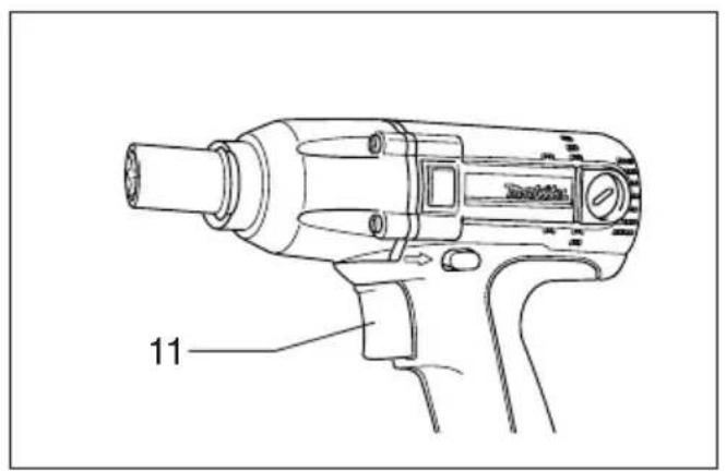
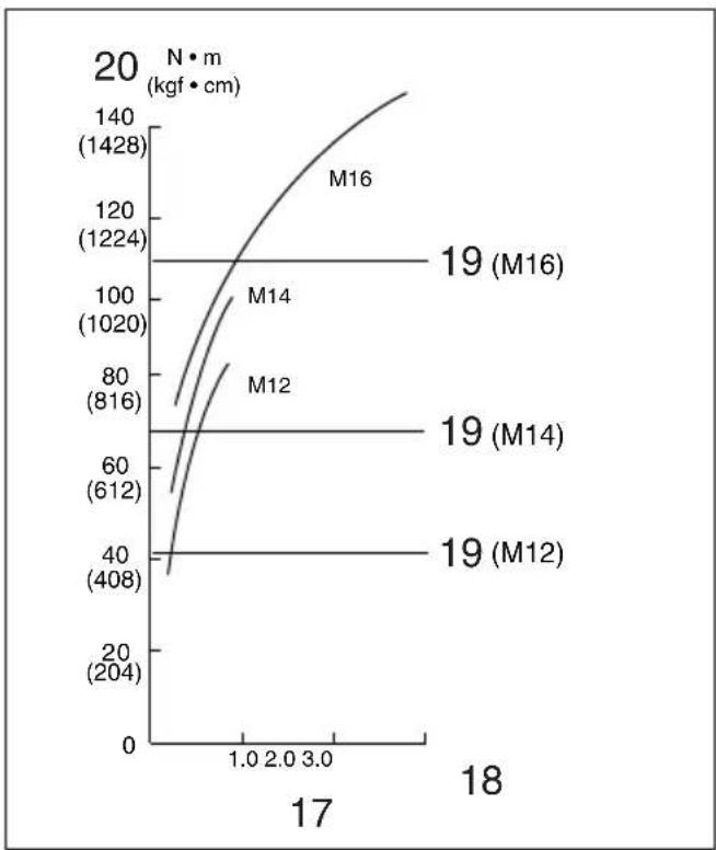
| 3 Battery cartridge | 11 Switch trigger | 19 Proper fastening torque for |
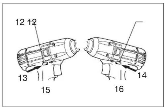
| 4 Terminal cover | 12 Reversing switch lever | 20 Fastening torque |
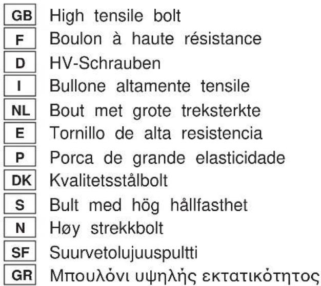
| 5 Charging lights | 13 A side | 21 Limit mark |
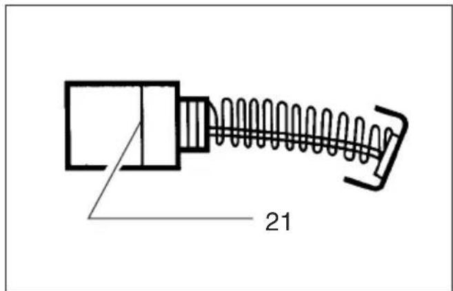
| 6 Battery charger | 14 B side | 22 Brush holder cap |
| 7 Socket | 15 Clockwise | 23 Screwdriver |
| 8 Anvil | 16 Counterclockwise |
SPECIFICATIONS
Model BTW150
Capacities
Standard bolt 10 mm — 16 mm
High tensile bolt 8 mm — 12 mm
Square drive 12.7 mm
No load speed (min) 0 — 2,300
Impacts per minute 0 — 3,000
Max. fastening torque 150·mN
Overall length 193 mm
Net weight (with battery cartridge) 1.9 kg
Rated voltage D.C. 14.4 V
- Due to our continuing program of research and development, the specifications herein are subject to change without notice.
• Note: Specifications may differ from country to country.
Safety Hints
For your own safety, please refer to the enclosed safety instructions.
IMPORTANT SAFETY INSTRUCTIONS FOR CHARGER & BATTERY CARTRIDGE ENC00
- SAVE THESE INSTRUCTIONS — This manual contains important safety and operating instructions for battery charger.
- Before using battery charger, read all instructions and cautionary markings on (1) battery charger, (2) battery, and (3) product using battery.
- CAUTION — To reduce risk of injury, charge only MAKITA type rechargeable batteries. Other types of batteries may burst causing personal injury and damage.
- Do not expose charger to rain or snow.
- Use of an attachment not recommended or sold by the battery charger manufacturer may result in a risk of fire, electric shock, or injury to persons.
- To reduce risk of damage to electric plug and cord, pull by plug rather than cord when disconnecting charger.
- Make sure cord is located so that it will not be stepped on, tripped over, or otherwise subjected to damage or stress.
- Do not operate charger with damaged cord or plug — replace them immediately.
- Do not operate charger if it has received a sharp blow, been dropped, or otherwise damaged in any way; take it to a qualified serviceman.
- Do not disassemble charger or battery cartridge; take it to a qualified serviceman when service or repair is required. Incorrect reassembly may result in a risk of electric shock or fire.
-
To reduce risk of electric shock, unplug charger from outlet before attempting any maintenance or cleaning. Turning off controls will not reduce this risk.
-
The battery charger is not intended for use by young children or infirm persons without supervision.
- Young children should be supervised to ensure that they do not play with the battery charger.
- If operating time has become excessively shorter, stop operating immediately. It may result in a risk of overheating, possible burns and even an explosion.
- If electrolyte gets into your eyes, rinse them out with clear water and seek medical attention right away. It may result in loss of your eyesight.
ADDITIONAL SAFETY RULES FOR CHARGER & BATTERY CARTRIDGE
- Do not charge battery cartridge when temperature is BELOW 10°C (50°F) or ABOVE 40°C (104°F).
- Do not attempt to use a step-up transformer, an engine generator or DC power receptacle.
- Do not allow anything to cover or clog the charger vents.
- Do not short the battery cartridge:
(1) Do not touch the terminals with any conductive material.
(2) Avoid storing battery cartridge in a container with other metal objects such as nails, coins, etc.
(3) Do not expose battery cartridge to water or rain. A battery short can cause a large current flow, overheating, possible burns and even a breakdown.
- Do not store the tool and battery cartridge in locations where the temperature may reach or exceed 50^ C ( 122^ F).
- Do not incinerate the battery cartridge even if it is severely damaged or is completely worn out. The battery cartridge can explode in a fire.
Be careful not to drop, shake or strike battery. - Do not charge inside a box or container of any kind. The battery must be placed in a well ventilated area during charging.
ADDITIONAL SAFETY RULES FOR TOOL
ENB025-1
- Be aware that this tool is always in an operating condition, because it does not have to be plugged into an electrical outlet.
-
Hold tool by insulated gripping surfaces when per- forming an operation where the cutting tool may contact hidden wiring. Contact with a "live" wire will ow, also make exposed metal parts of the tool "live" and make shock the operator.
-
Wear ear protectors.
Check the socket carefully for wear, cracks or damage before installation.
5. Hold the tool firmly.
6. Always be sure you have a firm footing.
7m Be sure no one is below when using the tool in high locations.
- The proper fastening torque may differ depending upon the kind or size of the bolt. Check the torque with a torque wrench.
SAVE THESE INSTRUCTIONS.
OPERATING INSTRUCTIONS
Installing or removing battery cartridge (Fig. 1)
- Always switch off the tool before insertion or removal of battery cartridge.
- To remove the battery cartridge, withdraw it from the tool while sliding the button on the side of the cartridge.
• To insert the battery cartridge, align the tongue on the battery cartridge with the groove in the housing and slip it into place. Always insert it all the way until it locks in place with a little click. If you can see the red part on the upper side of the button, it is not locked completely. Insert it fully until the red part cannot be seen. If not, it may accidentally fall out of the tool, causing injury to you or someone around you.
- Do not use force when inserting the battery cartridge. If the cartridge does not slide in easily, it is not being inserted the correctly.
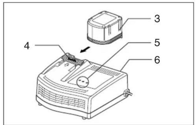
Charging (Fig. 2)
-
Plug the battery charger into the proper A/C voltage source. Two charging lights will flash in green color repeatedly.
-
Insert the battery cartridge into charger until it stops adjusting to the guide of charger. Terminal cover of charger can be opened with inserting and closed with pulling out the battery cartridge.
-
When the battery cartridge is inserted, the charging light color will change from green to red and charging will begin. The charging light will keep lighting up lit steadily during charging. One red charging light indicates charged condition in 0 – 80% and two red ones indicates 80 – 100%.
-
With finish of charge, the charging lights will change from two red ones to two green ones.
-
If you leave the battery cartridge in the charger after the charging cycle is complete, the charger will switch into its "trickle charge (maintenance charge)" mode which will last approximately 24 hours.
-
After charging, unplug the charger from the power source. Refer to the table below for the charging time.
| Battery type Capacity (mAh) Number of cells Charging time | ||||
| BH1420 2,000 12 Approx. 30 min. | ||||
| BH1433 3,300 12 Approx. 50 min. | ||||
NOTE:
- The battery charger is for charging Makita-battery cartridge. Never use it for other purposes or for other manufacture batteries.
- When you charge a new battery cartridge or a battery cartridge which has not been used for a long period of it may not accept a full charge. This is a normal condition and does not indicate a problem. You can recharge the battery cartridge fully after discharging it completely and recharging a couple of times.
- If you charge a battery cartridge from a just-operated battery cartridge which has been left in a location exposure to direct sunlight for a long time, the charging light may flash in red color. If this occurs, wait for a while. Charging will begin after the battery cartridge is cooled by the cooling installed in the charger. When the temperature on batteries more than approx. 70°C, two charging lights may flash in red color, and when approx. 50°C – 70°C, one charging light in red color.
- If the charging light flashes alternately in green and red color, charging is not possible. The terminals on the cha or battery cartridge are clogged with dust or the battery cartridge is worn out or damaged.
Cooling system
- This charger is equipped with cooling fan for heated battery in order to enable the battery to prove its own performance. Sound of cooling air comes out during cooling, which means no trouble on the charger.
- Yellow light will flash for warning in the following cases. - Trouble on cooling fan
- Incomplete cool down of battery, such as, being clogg with dust
The battery can be charged in spite of the yellow warm light. But the charging time will be longer than usual in case.
Check the sound of cooling fan, vent on the charger and battery, which can be sometime clogged with dust.
- The cooling system is in order although no sound of cooling. e. fan comes out, if the yellow warning light will not flash.
- 's Always keep clean the vent on charger and battery for cooling.
• The products should be sent to repair or maintenance, if the time yellow warning light will frequently flash.
Conditioning charge
Conditioning charge can extend the life of battery by automatically searching the optimum charging condition for the batteries in every situation.
The battery employed in the following conditions repeatedly, will be worn out shortly, and yellow warning light may flash.
1. Recharge of battery with its high temperature
2. Recharge of battery with its low temperature
3. Recharge of full charged battery
14. Over-discharge of battery (continue to discharge battery in spite of down of power.)
5. Recharge under broken cooling system
The charging time of such battery is longer than usual.
Trickle charge (Maintenance charge)
If you leave the battery cartridge in the charger to prevent spontaneous discharging after full charge, the charger will switch into its “trickle charge (maintenance charge)” mode
and keep the battery cartridge fresh and fully charged.
Tips for maintaining maximum battery life
- Charge the battery cartridge before completely discharged.
Always stop tool operation and charge the battery cartridge when you notice less tool power.
- Never recharge a fully charged battery cartridge.
Overcharging shortens the battery service life.
this Charge the battery cartridge with room temperature at 10^ C – 40^ C ( 50^ F – 104^ F).
Let a hot battery cartridge cool down by inserting it into the charger.
- Charge the Nickel Metal Hydride battery cartridge when NOTE:
you do not use it for more than six months.
Selecting correct socket
Always use the correct size socket for bolts and nuts. An incorrect size socket will result in inaccurate and inconsistent fastening torque and/or damage to the bolt or nut.
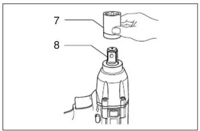
Installing or removing socket (Fig. 3 & 4)
CAUTION:
Always be sure that the tool is switched off and the battery cartridge is removed before installing or removing the socket.
1. For socket without O-ring and pin
To install the socket, push it onto the anvil of the tool it locks into place.
To remove the socket, simply pull it off.
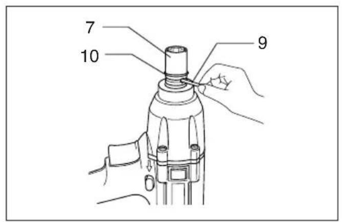
2. For socket with O-ring and pin
Move the O-ring out of the groove in the socket and remove the pin from the socket. Fit the socket onto the 2. anvil of the tool so that the hole in the socket is aligned with the hole in the anvil. Insert the pin through the hole, the socket and anvil. Then return the O-ring to the original position in the socket groove to retain the pin. To remove the socket, follow the installation procedures in reverse. 3.
Switch action (Fig. 5)
CAUTION:
Before inserting the battery cartridge into the tool, always check to see that the switch trigger actuates properly and returns to the "OFF" position when released.
To start the tool, simply pull the trigger. Tool speed is increased by increasing pressure on the trigger. Release the trigger to stop.
Reversing switch action (Fig. 6)
CAUTION:
- Always check the direction of rotation before operation.
- Use the reversing switch only after the tool comes to a complete stop. Changing the direction of rotation before the tool stops may damage the tool.
- When not operating the tool, always set the reversing swift lever to the neutral position.
This tool has a reversing switch to change the direction of rotation. Depress the reversing switch lever from the Aside clockwise rotation or from the B side for counterclockwise rotation. When the reversing switch lever is in the neutral position, the switch trigger cannot be pulled.
Operation
CAUTION:
Always insert the battery cartridge all the way until it locks in place. If you can see the red part on the upper side of the button, it is not locked completely. Insert it fully until the red part cannot be seen. If not, it may accidentally fall out of the tool, causing injury to you or someone around you.
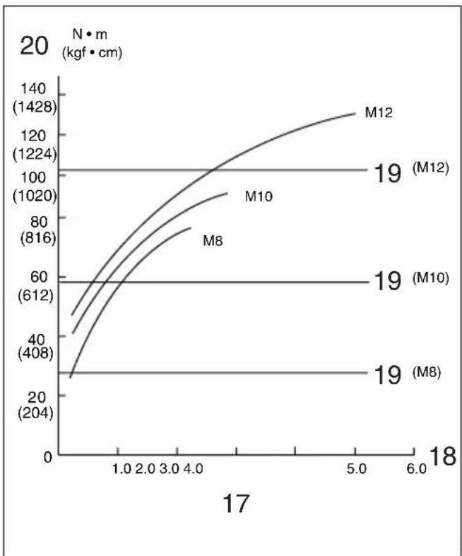
The proper fastening torque may differ depending upon the kind or size of the bolt, the material of the workpiece to be fastened, etc. The relation between fastening torque and fastening time is shown in Fig. 7 for standard bolt or Fig. 8 for high tensile bolt. Hold the tool firmly and place the socket over the bolt or nut. Turn the tool on and fasten for the proper fastening time.
- When fastening screw M8 or smaller, carefully adjust pressure on the switch trigger so that the screw is not damaged.
- Hold the tool pointed straight at the bolt.
If you fasten the bolt for a time longer than shown in the figure, the bolt or the socket may be overstressed, damaged, etc. Before starting your job, always perform a test operation to determine the proper fastening time for your bolt. Especially for the bolt other than M8, perform the above test operation to prevent the trouble on socket or bolt, etc.
The fastening torque is affected by a wide variety of factors including the following. After fastening, always check the torque with a torque wrench.
- When the battery cartridge is discharged almost completely, voltage will drop and the fastening torque will be reduced.
Socket
- Failure to use the correct size socket will cause a in reduction in the fastening torque.
• A worn socket (wear on the hex end or square end) will cause a reduction in the fastening torque.
Bolt
- Even though the torque coefficient and the class of bolt are the same, the proper fastening torque will differ according to the diameter of the bolt.
-
Even though the diameters of bolts are the same, the proper fastening torque will differ according to the torque coefficient, the class of bolt and the bolt length.
-
The manner of holding the tool or the material of driving position to be fastened will affect the torque.
- Operating the tool at low speed will cause a reduction in the fastening torque.
MAINTENANCE
CAUTION:
Always be sure that the tool is switched off and the battery cartridge is removed before carrying out any work on the tool.
Replacement of carbon brushes (Fig. 9 & 10)
Replace carbon brushes when they are worn down to the limit mark. Both identical carbon brushes should be replaced at the same time.
To maintain product safety and reliability, repairs, maintenance or adjustment should be carried out by a Makita Authorized Service Center.
1 Partie rouge
2 Bouton
3 Batterie
4 Couvre-bornes
VEILIGHEIDSVOORSCHRIFTEN VOOR ACCULADER EN ACCU
VEILIGHEIDSVOORSCHRIFTEN VOOR ACCULADER EN ACCU
Reversbryter (Fig. 6)
NB!
EC-DECLARATION OF CONFORMITY
The undersigned, Yasuhiko Kanzaki, authorized by Makita Corporation, 3-11-8 Sumiyoshi-Cho, Anjo, Aichi 446-8502 Japan declares that this product
(Serial No.: series production)
manufactured by Makita Corporation in Japan is in compliance with the following standards or standardized documents,
EN50260, EN55014,
in accordance with Council Directives, 89/336/EEC and 98/37/EC.
FRANÇAISE
DÉCLARATION DE CONFORMITÉ CE
Michigan Drive, Tongwell, Milton Keynes,
Bucks MK15 8JD, ENGLAND
PORTUGUÊS
EU-DEKLARATION OM KONFORMITET
Undertegnede, Yasuhiko Kanzaki, med fuldmagt fra Makita Corporation, 3-11-8 Sumiyoshi-Cho, Anjo, Aichi 446-8502
Michigan Drive, Tongwell, Milton Keynes,
Bucks MK15 8JD, ENGLAND
ENGLISH
EC-DECLARATION OF CONFORMITY
The undersigned, Yasuhiko Kanzaki, authorized by Kao Lung Tamura Electronics Co., Ltd. No. 4 Industry 1st St Ping Tung Industry District Chiao Nan Li, Ping Tung City Taiwan declares that this battery charger
(Serial No.: series production)
manufactured by Kao Lung Tamura Electronics Co., Ltd. Taiwan is in compliance with the following standards or standardized documents,
in accordance with Council Directives, 73/23/EEC and 89/336/EEC.
ITALIANO
DÉCLARATION DE CONFORMITÉ CE
Michigan Drive, Tongwell, Milton Keynes,
Bucks MK15 8JD, ENGLAND
PORTUGUÊS
Lung Tamura Electronics Co., Ltd. No. 4 Industry 1st Street
Ping Tung Industry District Chiao Nan Li, Ping Tung City
Taiwan, declara que este carregador de bateria
Ping Tung Industry District Chiao Nan Li, Ping Tung City, Taiwan bekrefter herved at dette batterilader
EU-DEKLARATION OM KONFORMITET
Lung Tamura Electronics Co., Ltd. No. 4 Industry 1st Str
Ping Tung Industry District Chiao Nan Li, Ping Tung City,
Taiwan, erklærer hermed, at dette batteriopladeren
(Løbenummer: serieproduktion)
fremstillet af Kao Lung Tamura Electronics Co., Ltd. i
Kao Lung Tamura Electronics Co., Ltd. No. 4 Industry 1st Street, Ping Tung Industry District Chiao Nan Li, Ping Tung
Lung Tamura Electronics Co., Ltd. No. 4 Industry 1st
Ping Tung Industry District Chiao Nan Li, Ping Tung
Ltd. No. 4 Industry 1st Street, Ping Tung Industry District
Chiao Nan Li, Ping Tung City, Taiwan, δηλώνει ότι αυτό
Michigan Drive, Tongwell, Milton Keynes,
Bucks MK15 8JD, ENGLAND
ENGLISH
Noise And Vibration Of Model
The typical A-weighted noise levels are
sound pressure level: 90 dB (A)
sound power level: 103 dB (A)
- Wear ear protection. -

- SPECIFICATIONS
- Model BTW150
- Safety Hints
- IMPORTANT SAFETY INSTRUCTIONS FOR CHARGER & BATTERY CARTRIDGE ENC00
- ADDITIONAL SAFETY RULES FOR CHARGER & BATTERY CARTRIDGE
- ADDITIONAL SAFETY RULES FOR TOOL
- SAVE THESE INSTRUCTIONS.
- OPERATING INSTRUCTIONS
- Installing or removing battery cartridge (Fig. 1)
- Charging (Fig. 2)
- NOTE:
- Cooling system
- Conditioning charge
- Trickle charge (Maintenance charge)
- Tips for maintaining maximum battery life
- Selecting correct socket
- Installing or removing socket (Fig. 3 & 4)
- CAUTION:
- For socket without O-ring and pin
- For socket with O-ring and pin
- Switch action (Fig. 5)
- Reversing switch action (Fig. 6)
- Operation
- Socket
- Bolt
- MAINTENANCE
- Replacement of carbon brushes (Fig. 9 & 10)
- VEILIGHEIDSVOORSCHRIFTEN VOOR ACCULADER EN ACCU
- Reversbryter (Fig. 6)
- NB!
- EC-DECLARATION OF CONFORMITY
- FRANÇAISE
- DÉCLARATION DE CONFORMITÉ CE
- PORTUGUÊS
- EU-DEKLARATION OM KONFORMITET
- ENGLISH
- ITALIANO
- Noise And Vibration Of Model
Brand : MAKITA
Model : BTW150
Category : Screwdriver