Warm - Frying Pan EDILKAMIN - Free user manual and instructions
Find the device manual for free Warm EDILKAMIN in PDF.



| Product type | Wood stove with water heater (thermostove) |
| Brand | Edilkamin |
| Model | Warm |
| Useful power | 19.7 kW |
| Overall efficiency | 80.7 % |
| Max heating volume | 515 m³ |
| Fuel | Dry wood (logs), <20% humidity |
| Water content | 40 liters |
| Max circuit pressure | 1.5 bar |
| Flue gas temperature | 225 °C |
| Flue outlet diameter | 150 mm |
| Weight (base version) | 250 kg |
| Weight (with plate warmer) | 274 kg |
| Dimensions (H x W x D) | 1060 x 566 x 640 mm (approximate) |
| Power supply | 230 V / 50 Hz |
| Protection rating | IP 40 |
| Air regulation | Automatic primary air, fixed secondary air |
| Safety | Thermal safety valve, overheat alarm, differential switch |
| Maintenance | Cold glass cleaning, ash vacuuming, annual flue sweeping |
| Optional kits | Hydraulic kits for domestic hot water production and open/closed expansion tank installation |
Frequently Asked Questions - Warm EDILKAMIN
User questions about Warm EDILKAMIN
0 question about this device. Answer the ones you know or ask your own.
Ask a new question about this device
Download the instructions for your Frying Pan in PDF format for free! Find your manual Warm - EDILKAMIN and take your electronic device back in hand. On this page are published all the documents necessary for the use of your device. Warm by EDILKAMIN.
USER MANUAL Warm EDILKAMIN
natural_image
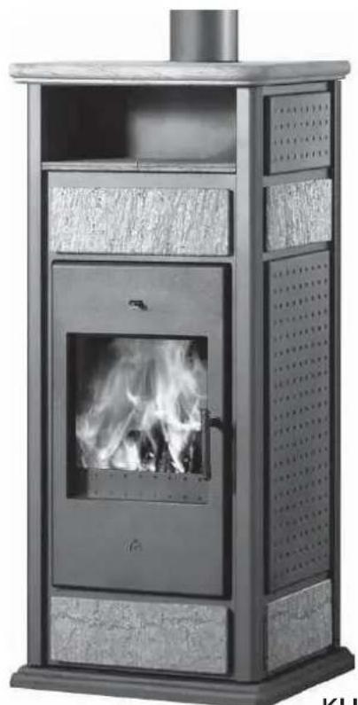
Exterior view of a modern outdoor stove with visible flames and ventilation grilles (no text or symbols)UK Installation, use and maintenance pag. 25
F Installation, usage et maintenance pag. 48
TERMOSTUFE A LEGNA, a marchio commerciale EDILKAMIN, denominate KLIMA - WARM e KLIMA/CS - WARM/CS
natural_image
Exterior view of a portable stove with visible flames and ventilation grilles (no text or symbols)KLIMA BASE
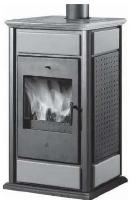
natural_image
Modern portable stove with visible flame inside, mounted on a metal frame (no text or symbols)WARM BASE
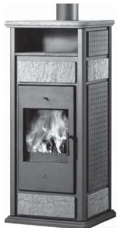
natural_image
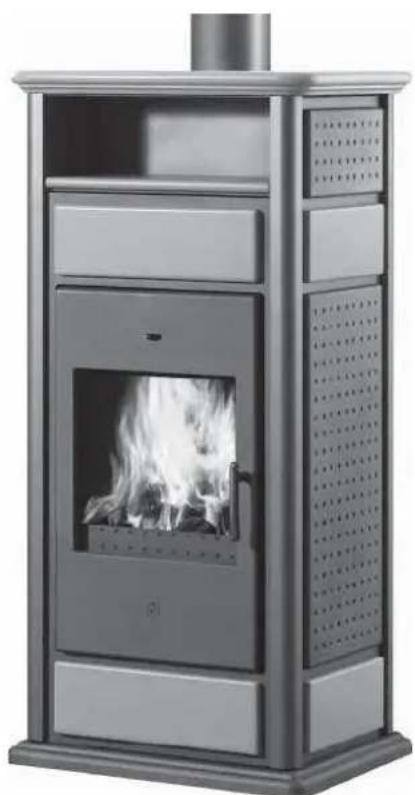
Exterior view of a modern outdoor stove with visible flames and ventilation grilles (no text or symbols)KLIMA con SCALDAVIVANDE
natural_image
Exterior view of a modern metal portable stove with visible flames and ventilation grilles (no text or symbols)natural_image
Close-up of a hand using a tool to adjust or install a component on a metal panel (no visible text or symbols)BY-PASS FUMI AUTOMATICO
natural_image
Close-up of a mechanical joint or bracket with a metallic component and a curved arrow indicating direction (no text or symbols visible)CHIUSURA AUTOMATICA ANTINA
natural_image
Interior view of a laboratory instrument cabinet with tubing and ventilation ducts (no visible text or labels)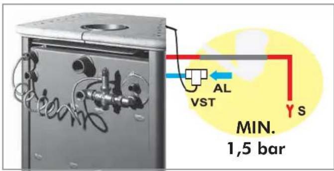
natural_image
Exterior view of a gray rectangular device with a small mark on the left, next to a large black question mark symbol on white background (no text or symbols on device)1 Anno
natural_image
Technical line drawing of a mechanical assembly with a vertical component and support structure (no text or symbols)2
3
4
- Canale da fumo
natural_image
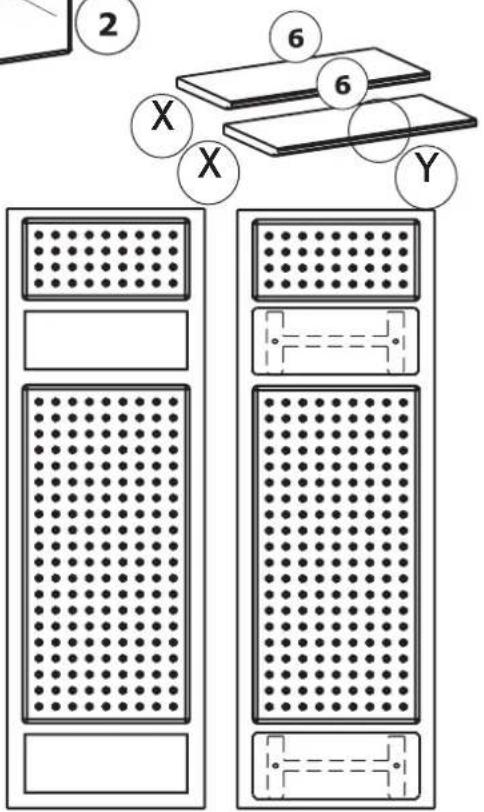
Two identical rectangular panels with dot patterns, each containing a grid of dots, and no text or symbols present.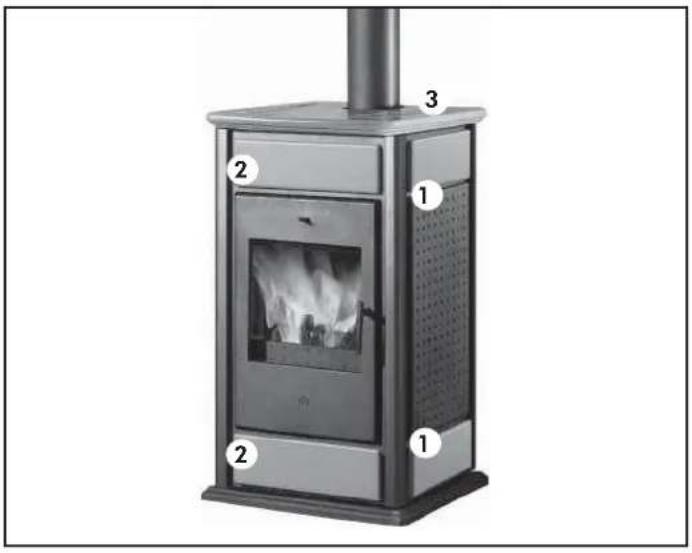
SET CERAMICHE
WARM / KLIMA BASE
Per WARM / KLIMA BASE:
SET CERAMICHE
WARM / KLIMA con scaldavivande
6 Raccorderia in rame
natural_image
Industrial piping system mounted on a metal frame, no visible text or symbolsKIT 1
cod. 261880
ESEMPIO DI IMPIANTO IDRAULICO PER TERMOSTUFA SENZA PRODUZIONE DI ACQUA CALDA SANITARIA + CALDAIA MURALE
CON UTILIZZO DI KIT 2
flowchart
graph TD
    A["RETE"] --> B["ST"]
    B --> C["TM"]
    C --> D["S"]
    D --> E["VE"]
    E --> F["V"]
    F --> G["AF"]
    G --> H["CA"]
    H --> I["MI"]
    I --> J["collettore"]
    J --> K["RA"]
    K --> L["RI"]
    L --> M["T"]
    M --> N["ACS"]
    N --> O["V"]
    O --> P["VR"]
    P --> Q["mi"]
    Q --> R["CO2"]
    R --> S["CO2"]
    S --> T["CO2"]
    T --> U["CO2"]
    U --> V["CO2"]
    V --> W["CO2"]
    W --> X["CO2"]
    X --> Y["CO2"]
    Y --> Z["CO2"]
    Z --> AA["CO2"]
    AA --> AB["CO2"]
    AB --> AC["CO2"]
    AC --> AD["CO2"]
    AD --> AE["CO2"]
    AE --> AF["CO2"]
    AF --> AG["CO2"]
    AG --> AH["CO2"]
    AH --> AI["CO2"]
    AI --> AJ["CO2"]
    AJ --> AK["CO2"]
    AK --> AL["CO2"]
    AL --> AM["CO2"]
    AM --> AN["CO2"]
    AN --> AO["CO2"]
    AO --> AP["CO2"]
    AP --> AQ["CO2"]
    AQ --> AR["CO2"]
AF: Acqua Fredda
CA: Caldaia murale
6 Raccorderia in rame
natural_image
Industrial piping system with valves and fittings (no visible text or symbols)KIT 2
cod. 261890
ESEMPIO DI IMPIANTO IDRAULICO PER TERMOSTUFA CON PRODUZIONE DI ACQUA CALDA SANITARIA + CALDAIA MURALE
CON UTILIZZO DI
KIT 3
flowchart
graph TD
    A["RE"] --> B["ST"]
    B --> C["TC"]
    C --> D["Ja"]
    D --> E["S"]
    E --> F["VE"]
    F --> G["V"]
    G --> H["AF"]
    H --> I["Tube di sciuvera @ 20 min"]
    I --> J["Tube di carico @ 18 min"]
    J --> K["CA"]
    K --> L["VI"]
    L --> M["RC"]
    M --> N["NI"]
    N --> O["mi"]
    O --> P["RA"]
    P --> Q["RI"]
    Q --> R["ACS"]
    R --> S["ACS"]
    S --> T["VST"]
    T --> U["VSP"]
    U --> V["SC 30"]
    V --> W["NC"]
    W --> X["VA"]
    X --> Y["SC 20"]
    Y --> Z["VR"]
    Z --> AA["PA"]
    AA --> AB["V"]
    AB --> AC["ACS"]
    AC --> AD["ACS"]
    AD --> AE["COLETTORE"]
    AE --> AF["MI"]
    AF --> AG["RF"]
    AG --> AH["VA"]
    AH --> AI["ACS"]
    AI --> AJ["ACS"]
ACS: Acqua Calda Sanitoria
AF: Acqua Fredda
CA: Caldaia murale
6 Raccorderia in rame
natural_image
Industrial piping system with valves and valves mounted on a metal frame (no visible text or labels)KIT 3
cod. 261900
ESEMPIO DI IMPIANTO IDRAULICO PER TERMOSTUFA CON PRODUZIONE DI ACQUA CALDA SANITARIA + CALDAIA MURALE
CON UTILIZZO DI KIT N3
flowchart
graph TD
    A["Tube di cosistenza Φ=28 mm"] --> B["S"]
    B --> C["VE"]
    C --> D["RF"]
    D --> E["RE"]
    E --> F["CA"]
    F --> G["TA"]
    G --> H["RETTE ELETTRICA"]
    H --> I["INT"]
    I --> J["RA"]
    J --> K["ACB"]
    K --> L["ACB"]
    L --> M["RCLETTORE"]
    M --> N["VA"]
    N --> O["V"]
    O --> P["VA"]
    P --> Q["V"]
    Q --> R["VA"]
    R --> S["V"]
    S --> T["VA"]
    T --> U["VA"]
    U --> V["VA"]
    V --> W["VA"]
    W --> X["V"]
    X --> Y["VA"]
    Y --> Z["V"]
    Z --> AA["VA"]
    AA --> AB["VA"]
    AB --> AC["V"]
    AC --> AD["VA"]
    AD --> AE["VA"]
    AE --> AF["VA"]
    AF --> AG["V"]
    AG --> AH["VA"]
    AH --> AI["VA"]
    AI --> AJ["V"]
    AJ --> AK["VA"]
    AK --> AL["VA"]
    AL --> AM["V"]
    AM --> AN["VA"]
    AN --> AO["V"]
    AO --> AP["VA"]
    AP --> AQ["V"]
    AQ --> AR["VA"]
    AR --> AS["V"]
    AS --> AT["VA"]
    AT --> AU["VA"]
    AU --> AV["VA"]
natural_image
Technical diagram of a mechanical or industrial system with pipes, valves, and a central heat exchanger (no text or labels visible)KIT N3
cod. 627690
ESEMPIO DI IMPIANTO IDRAULICO PER TERMOSTUFA CON PRODUZIONE DI ACQUA CALDA SANITARIA + CALDAIA MURALE
CON UTILIZZO DI KIT N3 BIS
flowchart
graph TD
    A["ST"] --> B["TCN"]
    B --> C["VA"]
    C --> D["VE"]
    D --> E["RF"]
    E --> F["CA"]
    F --> G["TA"]
    G --> H["RE"]
    H --> I["RC"]
    I --> J["COLLECTORE"]
    J --> K["RA"]
    K --> L["ACS"]
    L --> M["VR"]
    M --> N["BY-pass"]
    N --> O["V"]
    O --> P["ACS"]
    P --> Q["V"]
    Q --> R["VA"]
    R --> S["ACS"]
    S --> T["VR"]
    T --> U["V"]
    U --> V["ACS"]
    V --> W["VR"]
    W --> X["V"]
    X --> Y["ACS"]
    Y --> Z["V"]
    Z --> AA["VA"]
    AA --> AB["ACS"]
    AB --> AC["V"]
    AC --> AD["VR"]
    AD --> AE["V"]
    AE --> AF["ACS"]
    AF --> AG["V"]
    AG --> AH["VA"]
    AH --> AI["ACS"]
    AI --> AJ["V"]
    AJ --> AK["VR"]
    AK --> AL["V"]
    AL --> AM["ACS"]
    AM --> AN["V"]
    AN --> AO["VA"]
    AO --> AP["ACS"]
    AP --> AQ["V"]
    AQ --> AR["VR"]
    AR --> AS["V"]
    AS --> AT["ACS"]
    AT --> AU["V"]
    AU --> AV["VA"]
    AV --> AW["ACS"]
CA Caldaia murale
natural_image
Technical diagram of a mechanical piping system with valves, actuators, and control panel (no text or labels)KIT N3 BIS
cod. 627860
ESEMPIO DI IMPIANTO IDRAULICO PER TERMOSTUFA CON PRODUZIONE DI ACQUA CALDA SANITARIA IN ACCUMULO + CALDAIA MURALE
CON UTILIZZO DI IDROKIT
flowchart
graph TD
    A["Tubo di sicurazza @ > 28 mm"] --> B["VEa"]
    B --> C["S"]
    C --> D["Tubo di carico @ > 18 mm"]
    D --> E["BoILER"]
    E --> F["TC"]
    F --> G["EV"]
    G --> H["SC 30"]
    H --> I["Jm"]
    I --> J["P"]
    J --> K["P"]
    K --> L["CA"]
    L --> M["Collettore"]
    M --> N["MI"]
    N --> O["RA"]
    O --> P["RI"]
    P --> Q["V"]
    Q --> R["ACS"]
    R --> S["Accumulate Valve"]
    S --> T["VR"]
    T --> U["VA"]
    U --> V["VR"]
    V --> W["VA"]
    W --> X["VA"]
    X --> Y["VA"]
    Y --> Z["VA"]
    Z --> AA["VA"]
    AA --> AB["VA"]
    AB --> AC["VA"]
    AC --> AD["VA"]
    AD --> AE["VA"]
    AE --> AF["VA"]
    AF --> AG["VA"]
    AG --> AH["VA"]
    AH --> AI["VA"]
    AI --> AJ["VA"]
    AJ --> AK["VA"]
    AK --> AL["VA"]
    AL --> AM["VA"]
    AM --> AN["VA"]
    AN --> AO["VA"]
    AO --> AP["VA"]
    AP --> AQ["VA"]
    AQ --> AR["VA"]
    AR --> AS["VA"]
    AS --> AT["VA"]
    AT --> AU["VA"]
    AU --> AV["VA"]
    AV --> AW["VA"]
    AW --> AX["VA"]
    AX --> AY["VA"]
    AY --> AZ["VA"]
    AZ --> BA["VA"]
    BA --> BB["VA"]
    BB --> BC["VA"]
    BC --> BD["VA"]
    BD --> BE["VA"]
    BE --> BF["VA"]
    BF --> BG["VA"]
    BG --> BH["VA"]
    BH --> BI["VA"]
    BI --> BJ["VA"]
    BJ --> BK["VA"]
    BK --> BL["VA"]
    BL --> BM["VA"]
    BM --> BN["VA"]
    BN --> BO["VA"]
    BO --> BP["VA"]
    BP --> BQ["VA"]
    BQ --> BR["VA"]
    BR --> BS["VA"]
    BS --> BT["VA"]
    BT --> BU["VA"]
    BU --> BV["VA"]
    BV --> BW["VA"]
    BW --> BX["VA"]
    BX --> BY["VA"]
    BY --> BZ["VA"]
ACS: Acqua Calda Sanitaria
AF: Acqua Fredda
natural_image
Industrial piping and valve assembly (no visible text or symbols)KIT 5
cod. 280590
ESEMPIO DI IMPIANTO IDRAULICO PER TERMOSTUFA CON PRODUZIONE DI ACQUA CALDA SANITARIA
CON UTILIZZO DI KIT 6
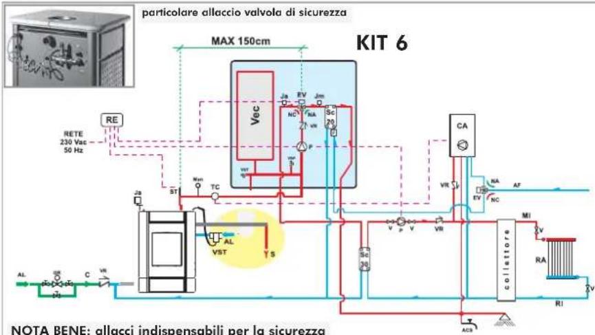
ACS: Acqua Calda Sanitaria
AF: Acqua Freddo
natural_image
Industrial equipment setup with pressure vessel, pipes, and control panel (no visible text or symbols)KIT 6
cod. 280600
thank you for choosing our KLIMA and WARM boiler-stoves
Before using your boiler-stove, please read this booklet carefully: it explains how to exploit all its features to the full in complete safety.
Please remember that installation MUST be carried out by qualified staff authorized according to Italian law 46/90.
Every country must refer to its own national regulations. If you require, EDILKAMIN can provide trained staff in every region in Italy (website www.edilkamin.com, under "technical assistance centres").
The manufacturer cannot be held liable for any damage deriving from boiler-stove use following incorrect installation, incorrect maintenance or misuse.
SAFETY INFORMATION:
THE BOILER-STOVE MUST NEVER BE RUN WITHOUT WATER IN THE SYSTEM.
"WATERLESS" IGNITION DAMAGES THE BOILER-STOVE.
•The boiler-stove is designed to heat water through the automatic combustion of wood in a firebox.
- The only risks which may derive from using the boiler-stove are linked with noncompliance with the installation instructions, direct contact with live electrical parts (outside) or with the fire or hot parts, and the introduction of foreign substances.
- Do not use flammable products to clean the smoke duct.
- Firebox components must only be cleaned WHEN COLD using a vacuum cleaner.
•The glass must be cleaned when COLD with a special cleaner (e.g. GlassKamin) and cloth. Do not clean when hot.
- During boiler-stove operation, the outlet pipes and door reach high temperatures.
- Do not keep objects which are not able to withstand heat in the immediate vicinity of the boiler-stove.
- NEVER use liquid fuels to light the boiler-stove or rekindle the embers.
- Do not block ventilation openings in the room where the boiler-stove is installed or air inlets in the boiler-stove itself.
- Do not get the boiler-stove wet, and do not put wet hands near electrical parts.
- Do not fit reducers on the smoke outlet pipes.
- The boiler-stove must be installed in a suitable place as regards fire regulations, and provided with all the facilities (power supply and outlet) it requires for correct operation.
Declaration of conformity
The undersigned EDILKAMIN S.p.a. with head office headquarters at Via Vincenzo Monti 47 - 20123 Milan - Italy - VAT IT00192220192
Declares under its own responsibility as follows:
The boiler-stoves specified below is in accordance with the 89/106/EEC (Construction Products)
THE BOILER-STOVES, trademark EDILKAMIN, called KLIMA - WARM e KLIMA/CS - WARM/CS
YEAR OF MANUFACTURE: Ref. Data nameplate
SERIAL NUMBER: Ref. Data nameplate
The compliance with the 89/106/EEC directive is besides determined by the compliance with the European standard:
KLIMA - WARM UNI EN 13240:2006
KLIMA/CS - WARM/CS UNI EN 13240:2006
Also declares as follows:
The boiler-stoves KLIMA - WARM e KLIMA/CS - WARM/CS is in compliance with the requirements of the European directives:
2006/95/EEC - Low voltage directive
2004/108/EEC - Electromagnetic compatibility directive
EDILKAMIN S.p.a. will decline all responsibility of malfunctioning or damage to the equipment in case of unauthorized substitution, assembly or modifications of any sort on the said equipment on the part of non-EDILKAMIN S.p.a. personnel.
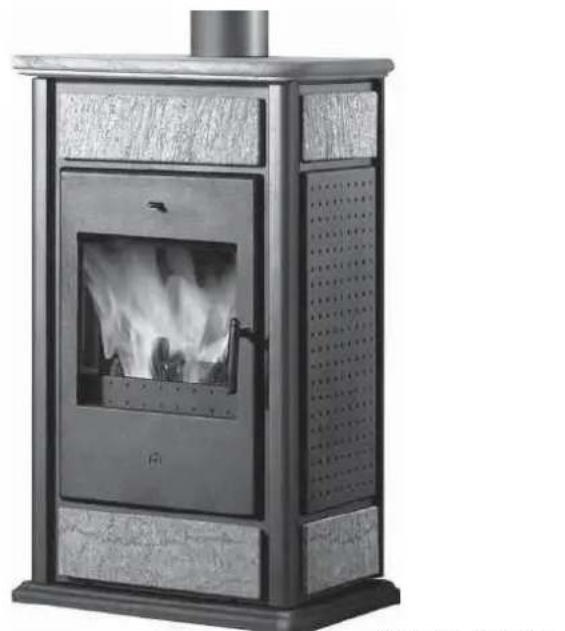
natural_image
Modern portable stove with visible flame inside, mounted on a metal frame (no text or symbols)BASIC KLIMA
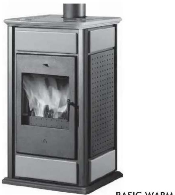
natural_image
Modern portable stove with visible flame inside, mounted on a metal frame (no text or symbols)BASIC WARM
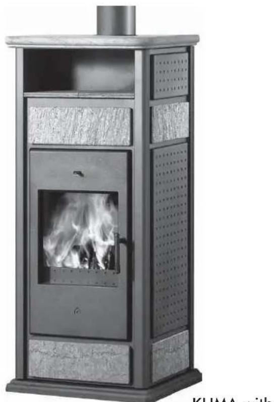
natural_image
Exterior view of a modern outdoor stove with visible flames and ventilation grilles (no text or symbols)KLIMA with HOTPLATE
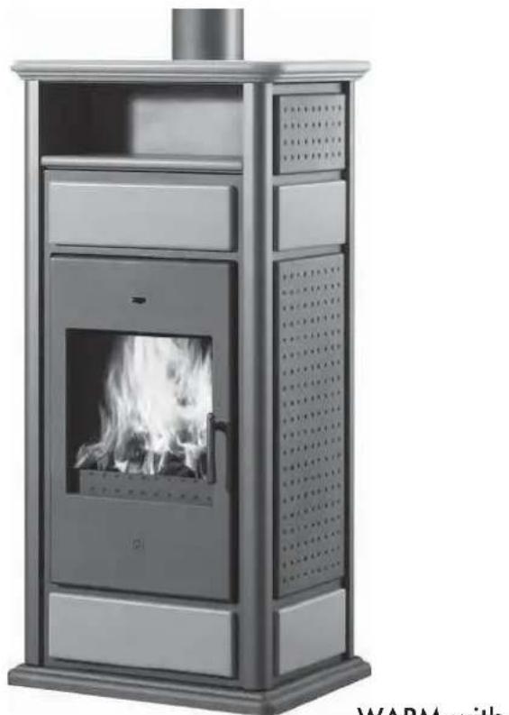
natural_image
Modern portable stove with visible flame inside, no text or symbols on the device itselfWARM with HOTPLATE
All models are available:
installation in an open expansion
or
version CS, with built-in coil operated by a heat discharge valve, for installation with closed expansion.
NOTES on fuel:
The KLIMA and WARM boiler-stoves are designed to burn wood.
In order NOT to jeopardize boiler-stove operation, do NOT burn other substances.
The calorific value of wood varies considerably according to its moisture content. The declared boiler-stove power output in kW may be obtained by burning the recommended quantity of wood, being careful not to overload the combustion chamber.
OPERATING PRINCIPLE/TECHNICAL DATA
The boiler-stove is designed to heat the room it is installed in by convection, radiation and the water found in it, which is sent to heat radiators and/or to the domestic hot water system (according to the type of system). The heat is generated by burning wood in the thick steel firebox.
The smoke leaves through the flue with natural draught.
Ash falls into the pan where it gathers for emptying.
Optimum performance is also obtained thanks to the following features:
,PRIMARY AIR REGULATION (for combustion)
Combustion air intake is automatically regulated by the control valve found on the back of the boiler-stove according to:
- the position of the knob
- the water temperature
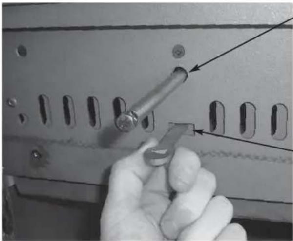
natural_image
Close-up of a hand using a tool to adjust or install a component on a metal panel (no visible text or symbols)AUTOMATIC SMOKE BY-PASS VALVE
During the ignition stage with the door open, the smoke shutter stays in an open position so that the smoke can reach the flue directly and easily to help combustion begin.
When combustion is well under way, closing the door also automatically closes the smoke shutter.
In this situation, the smoke is diverted before reaching the flue so that it flows against and transfers heat to the hollow jackets and heat exchanger tubes.
-SECONDARY AIR REGULATION
The fixed secondary air flow goes directly to the firebox through the slits in the upper part of the firebox door. As well as allowing the ceramic glass to clean itself, it helps burn any gases which may be given off by incomplete wood combustion, thus reducing dangerous gas emissions into the environment.
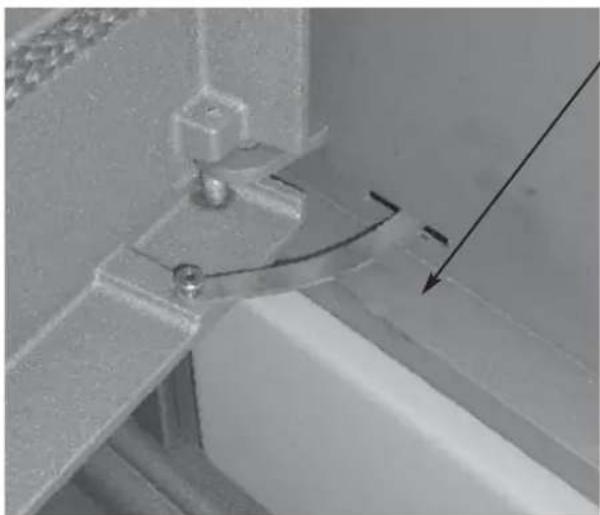
natural_image
Close-up of a mechanical joint or bracket with a metallic component and a curved arrow indicating direction (no text or symbols visible)AUTOMATIC DOOR CLOSURE
The firebox door (made of cast iron with high temperature resistant ceramic glass) allows a panoramic view of the fire and closes automatically with a spring return for optimum combustion.
OPERATING PRINCIPLE/TECHNICAL DATA
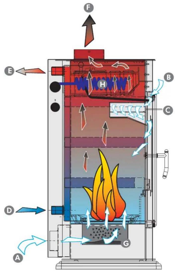
A Primary air inlet
B Secondary air inlet
C Secondary air regulation lever
D Cold water inlet
E Hot water outlet
F Smoke outlet
G Ashpan
H Coil
| TECHNICAL AND HEATING SPECIFICATIONS | |||
| Klima/Warm Klima CS/Warm CS | |||
| Available power 19,7 14 kW | |||
| Power output for water 11,6 10 kW | |||
| Power output to room 8,1 4 kW | |||
| Overall efficiency 80,7 81,6 % | |||
| Smoke temperature 225 234 °C | |||
| Smoke flow 18,2 11,3 g/s | |||
| Water content | 40 | 40 | l |
| Fuel consumption max | 5,5 4 kg/h | ||
| Minimum draught | 12 | 12 | Pa |
| Maximum pressure | 1,5 | 1,5 | bar |
| Klima weight (basic/hotplate) including the packaging | 275/305 | 278/308 | kg |
| Warm weight (basic/hotplate) including the packaging | 250/274 | 253/276 | kg |
| Smoke outlet diameter | 15 | 15 | cm |
| Heating capacity * | 515 | 365 | m^3 |
* The heatable room dimensions are calculated assuming the use of wood of the type described in the note, and home insulation which complies with Italian law No. 10/91, and subsequent changes together with an expected heat output of 33Kcal / m^3 hour.
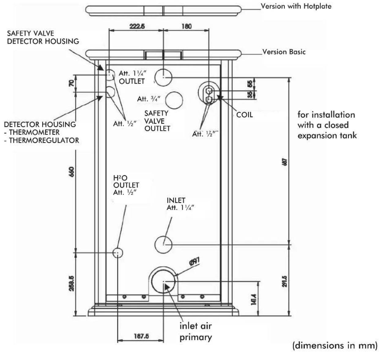
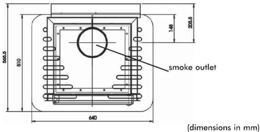
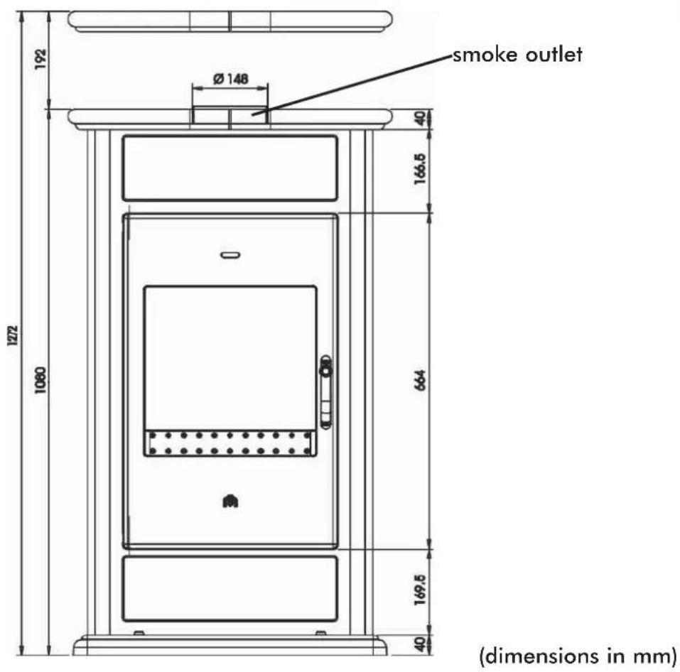
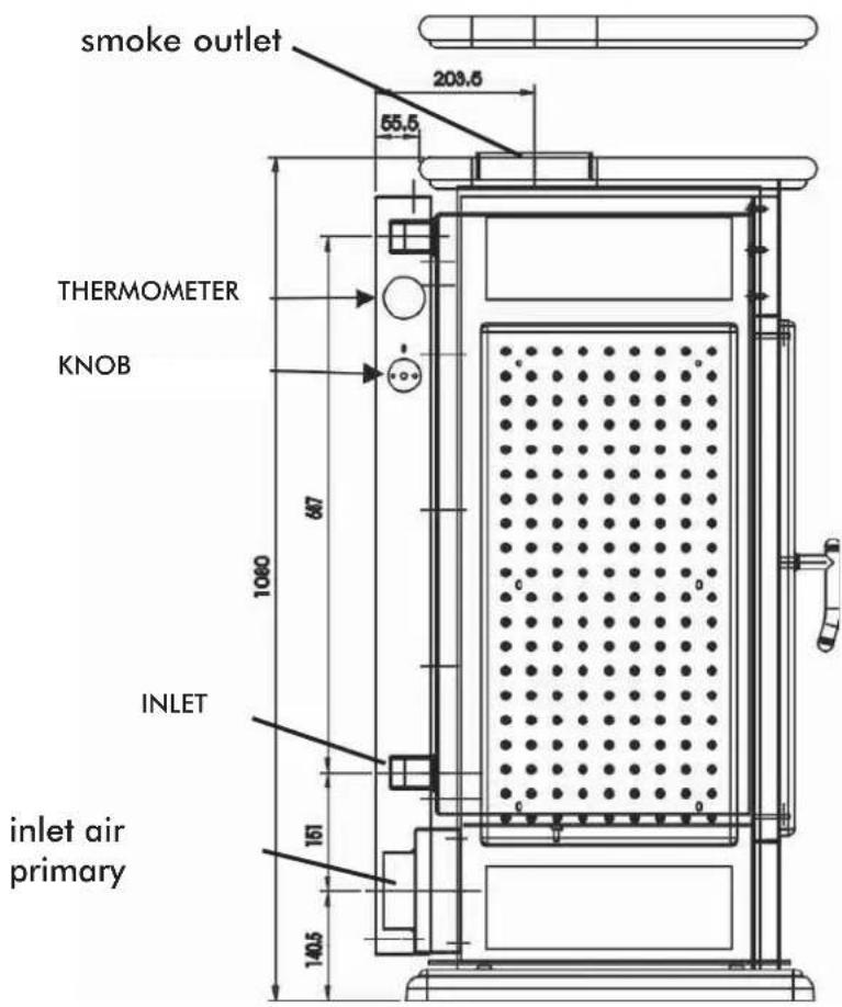
(dimensions in mm)
GENERAL SAFETY REGULATIONS
ONLY BOILER-STOVES WITH A COIL OPERATED BY A HEAT DISCHARGE VALVE MAY BE INSTALLED ON SYSTEMS WITH A CLOSED EXPANSION TANK.
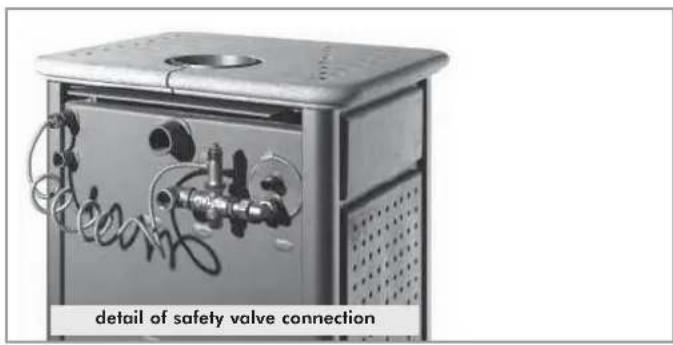
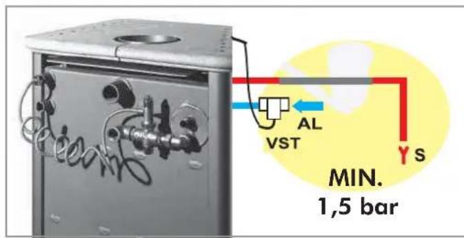
1st year
In closed expansion tank installations:
- The installer is responsible for installing the system correctly. The installer must take Italian standards UNI 10683/2005 - 9615/90 - 10412:2 into consideration.
- Everything must be done by authorized staff according to Italian law 46/90.
- The valve must be connected to the cooling circuit with a minimum pressure of 1.5 bars.
AL = Coil filling, always with a minimum pressure of 1.5 bars.
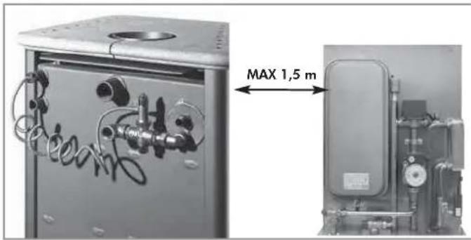
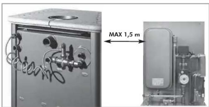
- Kits 5 or 6 must be installed 150 cm from the boiler-stove.
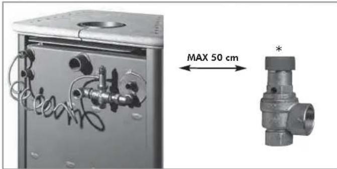
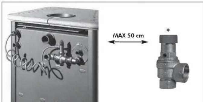
- An overpressure valve must be installed MAX 50 cm away. The valve is provided as standard by EDILKAMIN.
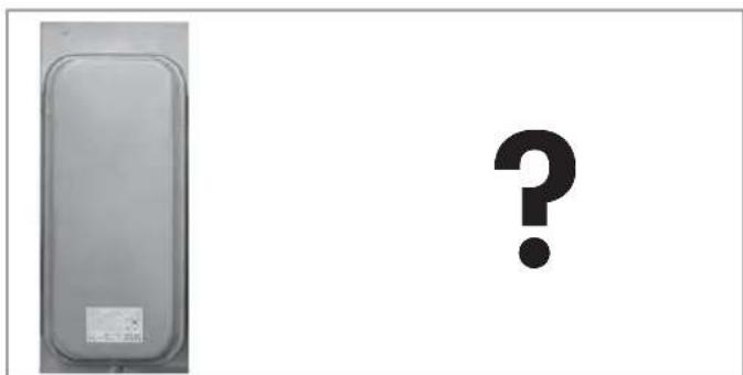
- A further expansion tank must be fitted in the system, of a size depending on the volume of water in the system itself.
• The safety valves must be checked at least once a year by staff authorized according to Italian law 46/90
KLIMA e WARM
for installation with an OPEN TANK
- The connections, commissioning and
verification of proper operation of the boiler-stoves must be carried out by qualified personnel, who can implement all connections in accordance with the laws in force, particularly with Italian D.M 37 Law No. 46/90, apart from complying with these instructions. - The boiler-stove and the system are filled with water that flows from the water inlet pipe (the diameter must not be less than 18 mm) to the open expansion tank.
- All the vents of the radiators must be opened during this phase so as to prevent air pockets from forming in the system which would obstruct the circulation of water.
NB:
- The open tank should be placed higher than 3 m from the highest radiator and lower than 15 m from boiler-stove.
- In any case, the tank must be high enough to create a greater pressure than that produced by the pump (circulator).
- The system must never be filled directly from the water mains as the pressure may be greater than that stipulated on the data plate of the boiler-stove.
- The safety pipe to the expansion tank must allow the water to flow freely, must not have taps and must be insulated properly.
- The water inlet pipe must not have taps nor curves.
- The maximum operating pressure must not exceed 1.5 bar
- The testing pressure is 3 bar.
- In places that reach very low temperatures, antifreeze liquid must be added to the water in the system.
- Never ignite the fire in the boiler-stove (not even as a test) unless the system is filled with water as this could cause irreparable damage.
- Connect the drains of the thermal relief valve (VST).
- The flow test of the system must be carried out with the expansion tank open.
- It is recommended to install a 6 bar safety valve on the hot sanitary water circuit so as to drain any excessive increase in the volume of the water in the heat exchanger.
- Place all the components of the system (circulator, heat exchanger, valves, etc.) in easily accessible points for routine and special maintenance procedures.
- It is recommended to prepare thermal insulation on the vaulted top part of the boiler
KLIMA/CS e WARM/CS
for installation with an CLOSED TANK
(additional regulations to those specified above).
- Be careful not to exceed 1.5 bar when filling the system.
- Only if a thermal relief valve actuates the coil can the boiler-stove be installed on a CLOSED TANK system.
- Consider the necessity of installing another CLOSED TANK.
- Make sure the drain is connected to the coil and the power supply is at least 1.5 bar.
- The upstream pressure of the cooling circuit must be at least 1.5 bar (UNI 10412/2 point 6.2).
Other than that described in this documentation, you are also asked to note the following UNI standards:
- No. 10683/2005 - firewood heat generators: installation requirements
- No. 9615/90 - calculating the internal dimensions of fireplaces
- No. 10412:2 - hot water heating systems. Specific safety requirements for systems provided with residential solid fuel burning appliances and combined boiler, not exceeding a total nominal heat input of 35 kW.
Particularly:
- Before carrying out any assembly it is important to verify compatibility of the appliance, as stipulated in UNI
10683/2005 standard, paragraphs 4.1 / 4.1.1 / 4.1.2. - When assembly is completed, the installer must implement "start-up operations" and issue documentation as required by UNI 10683/2005 standard in paragraphs 4.6 and 5, respectively.
- The connections, commissioning and verification of proper operation of the boiler-stove must be carried out by qualified personnel, who can implement the electrical and plumbing connections as required by UNI standards
10683/2005, paragraph 4.5 and 10412:2, apart from complying with these assembly instructions.
LOCATION
The boiler-stove is delivered on a pallet covered with a cardboard box. Remove the boiler-stove from its packaging, check that the model is the one ordered, and make sure it has not been damaged during transport.
Any complaints must be made to the retailer (on the accompanying consignment note).
Before positioning the boiler-stove, make sure the flue is suitable for the smoke produced.
The boiler-stove must be level for correct operation.
Check the load-bearing capacity of the floor. If insufficient, it must be reinforced. If the boiler-stove is installed on a floor made of flammable material, it is advisable to place it on tiles
AIR INTAKE
The room where the boiler-stove is located must have an air intake with cross section of at least 200 cm ^2 to ensure replenishment of the air consumed by combustion.
1
natural_image
Technical line drawing of a mechanical assembly with a vertical component and support structure (no text or symbols)2
3
4
- SMOKE DUCT
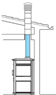
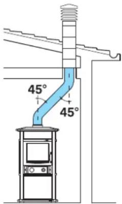
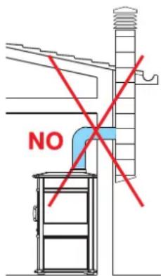
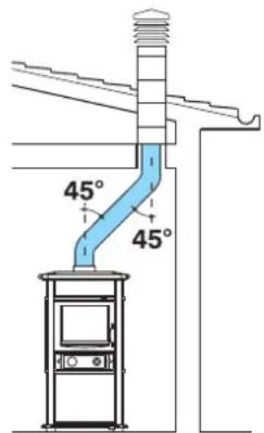
The term smoke duct is taken to mean the duct which connects the boiler-stove smoke outlet pipe to the flue inlet.
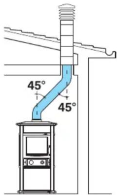
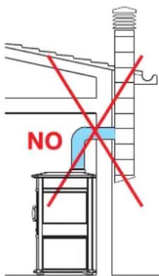
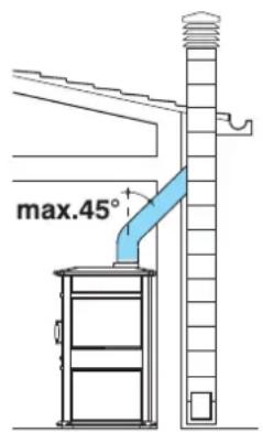
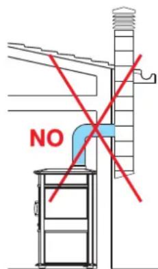
The smoke duct must be made using non-flexible steel or ceramic pipes. Flexible metal or fibrocement pipes must not be used. Horizontal or downward sloping sections must be avoided. Any changes in cross-section must occur at the outlet from the boiler-stove, and not at the connection with the flue, for instance.
Bends of greater than 45^ are not allowed (see figures 1, 2, 3 and 4). The joint between the steel pipe and the boiler-stove smoke outlet must be sealed with high temperature mastic.
In addition to that mentioned above, please consider the indications stipulated in UNI 10683/2005 standard, paragraph 4.2: "connection to the smoke outlet system" and its subsections.
• SMOKE OUTLET
The chimney flue is intended as the channel that reaches the building roof from the thermo stove room of use.
The basic characteristics of the flue are:
• capacity to support a smoke temperature of at least 450°C;
- suitably insulated to prevent condensate from forming;
- constant cross-section, almost vertical and devoid of bends greater than 45^ ;
- preferably circular internal cross-section; in the case of rectangular cross-sections, the maximum ratio between the sides must be 1.5;
- internal cross-section with surface area equal at least to the size shown in the product specifications;
- connected to only one hearth.
In the case of old or oversized flues, it is advisable to line them with stainless steel pipes of a suitable diameter and suitable insulation.
• BUTTERFLY VALVE
It is advisable to include a butterfly valve (shutter) on the smoke duct. The valve must be easy to operate and found in a place which allows it to be distinguished externally from the regulation knob. The valve must stay firm in the set position, and must not close automatically.
• CHIMNEY
The basic features of the chimney pot are:
- internal cross-section at the base equal to the flue cross-section;
- outlet cross-section not less than twice the flue cross-section;
- a position in the open air above the roof beyond the reflux area.
INSTALLATION INFORMATION
- Wood-burning boiler-stoves must be installed "in a workmanlike manner" in compliance with the SAFETY REGULATIONS in force and, most importantly, by qualified expert staff.
• We advise you to read these instructions and general rules of conduct carefully in order to get the most from your wood-burning boiler-stove.
• Furthermore, due to the distinct characteristics of each installation, EdilKamin declines all responsibility for breakdown, damage or malfunction caused by failure to comply with these instructions for use
COMPATIBILITY CHECK WITH OTHER DEVICES
According to Italian standard UNI 10683/05, the boiler-stove must NOT be installed in the same room as extractor fans, type B gas equipment or devices which lower the pressure in the room.
Caution: If extractor fans operate in the same room or space where the device is installed, they may cause problems.
CAUTION: The boiler-stove has been designed to work with the door closed only. Heat is propagated by radiation and convection.
FIRE SAFETY DISTANCES
The boiler-stove must be installed in compliance with the following safety conditions:
- minimum distance at the sides from medium-level flammable materials: 80 cm;
- minimum distance at the rear from medium-level flammable materials: 20 cm;
- easily flammable materials must not be located less than 80 cm from the front of the boiler-stove;
- if the boiler-stove is installed on a flammable floor, a sheet of heat insulating material must be placed between the stove and the floor, which protrudes by at least 20 cm at the sides and 40 cm at the front.
Objects made of flammable materials must not be placed on the boiler-stove or at less than the safety distance from it.
If the smoke outlet pipe is connected to walls made of wood or other flammable materials, it must be insulated with ceramic fibre or other materials with similar characteristics.
WATER CONNECTIONS:
THE BOILER-STOVE MUST NEVER BE RUN WITHOUT WATER IN THE SYSTEM. "WATERLESS" IGNITION DAMAGES THE BOILER-STOVE.
Plumbing must be carried out by qualified staff authorized to issue declarations of conformity in compliance with Italian law No. 46/90.
Water treatment
Add antifreeze, scale inhibitors and corrosion inhibitors. If the filling and top-up water has a hardness greater than 35^ F, use a water softener to reduce it. Refer to Italian standard UNI 8065-1989 (Water treatment in domestic heating systems).
PRACTICAL NOTE
When connecting the outlet, inlet and drain piping (see page 25), fit suitable means to make moving the boiler-stove easy in the future (for example, flexible piping for the first 0.5 m).
The boiler-stove must be connected to the water pipes by qualified plumbers.
In Italy, refer to Italian Standards UNI 10683 and UNI 10412:2. In other countries, refer to the local laws in force.
The KLIMA and WARM boiler-stoves may be installed in two different types of system:
- Open systems (the most usual): with an open expansion tank.
- Closed systems (only possible with KLIMA CS and WARM CS) with a closed expansion tank.
Boiler-stove installation in an open system:
To install the KLIMA and WARM boiler-stoves with open expansion tank:
- The expansion tank must be located at more than 3m from the highest point of the last radiator to be heated or 2-3 metres above the boiler-stove if a plate heat exchanger is used.
- The height of the expansion tank must in any case create a greater pressure than that produced by the circulation pump.
- The expansion tank safety pipe must not be closed and must not be fitted with a cock.
- The expansion tank safety pipe must not be less than 28 mm in diameter.
- The filling pipe must not be closed, and must not be fitted with cocks or bends.
- The filling pipe must not be less than 18 mm in diameter.
- The maximum working pressure must not be greater than 1.5 bars.
- It must be tested at a pressure of 3 bars.
- Never fill the system directly with mains pressure water since this may be greater than the boiler-stove test pressure.
The boiler-stove and system must be filled through the open expansion tank by gravity through the filling pipe (not less than 18 mm in diameter).
Connect the heat discharge valve (VST) and safety valve (VS) outlets.
- A residual current circuit breaker must be fitted upstream of the device and the whole boiler-stove electric circuit. The pump, the valve and the metal parts of the boiler-stove must also be earthed.
Compliance with regulations concerning earth connections is essential for the safety of people.
- During this stage, open all radiator vents to prevent the formation of air pockets in the system which would prevent water circulation.
Boiler-stove installation with closed expansion tank:
To install the KLIMA CS and WARM CS boiler-stoves with a closed expansion tank, the boiler-stove must have a cooling coil with heat discharge valve.
An EDILKAMIN assembled kit must be used: kit 5 without domestic hot water production (code n. 280590) or kit 6 with domestic hot water production (code n. 280600) according to the case.
- The maximum working pressure must not be greater than 1.5 bars.
- It must be tested at a pressure of 3 bars.
- Never fill the system directly with mains pressure water since this may be greater than the boiler-stove test pressure.
- Never turn on the fire in the boiler-stove (not even as a test) if the system is not filled with water; it could be irreversibly damaged.
- The system must be tested with the expansion tank open.
- It is advisable to install a 6 bar safety valve on the domestic hot water circuit to relieve the increase in water volume in the heat exchanger.
- Arrange all the system components (circulation pump, heat exchanger, valves, etc.) in easily accessible places for routine and special maintenance.
- EdilKamin is only liable for correct operation if the boiler-stove is used in compliance with the documents supplied with it.
- Assess the need for a further system expansion tank.
To make boiler-stove installation quicker and surer, EDILKAMIN offers assembled kits:
- 1-2-3-N3-N3 BIS-IDROKIT to install KLIMA and WARM with an open expansion tank.
- 5-6-IDROKIT to install KLIMA CS and Warm CS with a closed expansion tank.
The choice of kit depends on the type of system you wish to set up.
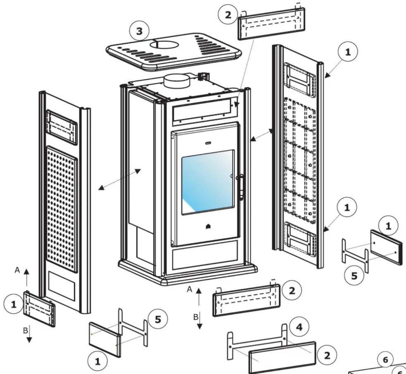
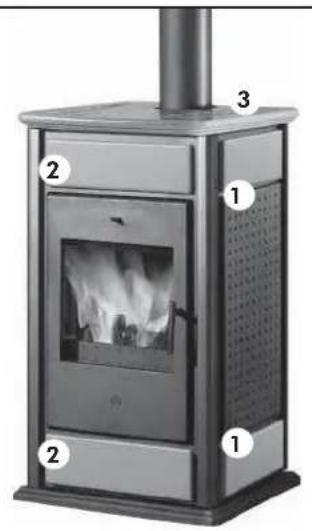
External covering assembly for BASIC WARM /KLIMA
If they are not already fitted (1), put the side panels into the grooves in the stove frame aluminium bars.
- Screw the metal bars (5) to the corresponding side ceramic tiles (1) using the screws provided.
- Place them into their housings in the side stove panels by slipping them in from above (A), then lock them in place by pushing them downwards (B).
- Screw the metal bars (4) to the corresponding front ceramic tiles (2) using the screws provided.
- Place them into their housings in the front stove panel by slipping them in from above (A), then lock them in place by pushing them downwards (B).
- Put the ceramic top (3) in place and centre it with the smoke outlet.
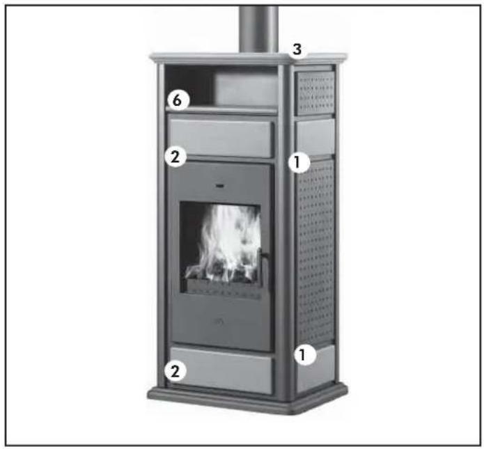
External covering assembly for WARM /KLIMA with HOTPLATE
- Proceed in the same way. See detail of side panels.
- After positioning the top (3), put the ceramic hotplate components in place (6)
natural_image
Exterior view of a portable stove with labeled components (no text or symbols beyond labels)CERAMIC SETS
BASIC WARM / KLIMA
Remove the tiles from the packaging and check the contents.
For BASIC WARM / KLIMA:
- 4 side tiles (1)
- 2 front tiles (2)
- 1 top (3)
CERAMIC SETS
WARM / KLIMA with hotplate
Remove the tiles from the packaging and check the contents.
For WARM / KLIMA with hotplate:
- 4 side tiles (1)
- 2 front tiles (2)
- 1 top (3)
- 1 hotplate (6)
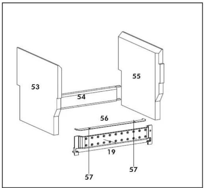
FIREBOX SCAMOLEX SET (cod. 624670)
- 1 Large left firebox scamolex (53)
- 1 Catch back firebox (54)
- 1 Large right firebox scamolex (55)
- 1 Stirrup flistening scamolex (56)
- 2 Self-tapping screws M4,2x9 (57)
- 1 Wood guard (19)
INSTALLATION SEQUENCE:
- Insert the rear fireplace stop (54), resting it on the bottom of the fireplace on the hearth.
- Insert the two right/left sides (53-55).
- Tighten the fastening bracket (56) to front fender (19) with supplied screws (57).
- Then insert the fender (19) in its original position.
- It is important to ensure that there is water in the boiler-stove and the system before igniting the boiler-stoves.
- The Company is responsible for the proper functioning of the product only if this is handled in accordance with the documentation supplied with the product itself.
Any unpleasant smells or smoke are caused by materials used during construction evaporating or drying.
This tends to die down after a few days.
N.B.: do not use alcohol, petrol (gasoline), kerosene or other liquid fuels to light the fire. Keep liquid fuels away from the fire. Do not use firelighters made from petroleum or chemical substances: they may cause serious damage to the firebox walls. Only use eco-friendly firelighters. Overloading (more kilos than in the table shown earlier) or excessively lively flames may damage the firebox compartment.
Practical advice
Incomplete combustion leads to excessive deposits on the heat exchanger. To avoid this, it is necessary to:
- burn dry wood;
• make sure the firebox contains a good bed of embers before adding other wood; - load large diameter logs with other smaller ones;
- make sure that at least one radiator is always on;
• turn on the pump switch; - fill the boiler-stove with a load of medium-small pieces of dry wood and light the fire;
- wait a few minutes until sufficient combustion is achieved;
- adjust the combustion using the thermoregulator with thermostat;
- o It is recommended to keep the radiators closed in the room where the boiler-stoveis installed since the heat radiated from the opening of the boiler-stoves itself is enough.
Fuel and heating value
Combustion has been optimized from the technical point of view both as regards the design of the firebox and relevant air supply, and emissions. Only use natural seasoned wood or wood briquettes as fuel. Damp, freshly cut or unsuitably stored wood has a high water content. Therefore it burns badly, produces a lot of smoke and gives off little heat. Only use firewood seasoned for a minimum of two years in a dry ventilated place. In this case, the water content is less than 20% by weight. This leads to a fuel saving, since seasoned wood has a decidedly greater heating value. One kilo of dry wood produces between 2000 and 2500 kcal/kg according to type, whereas one kilo of dry wood of the same type after two years of seasoning produces between 3500 and 4000 kcal/kg.
Never use liquid fuels, such as petrol (gasoline), alcohol or similar substances. Never burn refuse.
Adding fuel
When "adding wood" it is advisable to use a protective glove to avoid accidental contact with hot parts. Open the door slowly. In this way, no vortexes are formed which may cause smoke to enter the room.
When is it time to add wood?
When the fuel has almost become embers.
During the combustion process
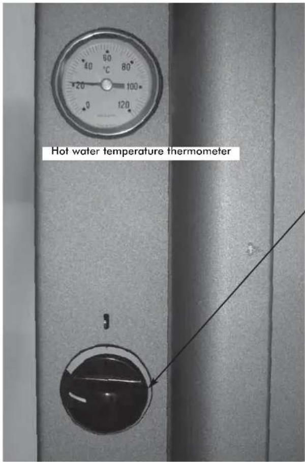
If the water temperature exceeds 90^ C because of too much wood being placed in the hearth, the thermal relief valve will be activated and the acoustic signal heard.
In this case you must proceed as follows:
- Wait until the temperature is lower than 80^ C; check the warning lights on the electronic regulator
- The hot water tap can be opened to speed up the cooling process if the boiler-stove is equipped with hot sanitary water.
Cleaning the glass pane
The glass must be cleaned when COLD with a cloth and a few drops of special cleaning liquid (GlassKamin). Do not clean when the boiler-stove is operating.
Cleaning the flue
According to different laws in various countries, it is necessary to have authorized staff clean the flue.
This must be done before periods of boiler-stove use and every time a layer of soot and tar (easily flammable substances) can be seen on the inside of the duct. When deposits reach a thickness of 5 - 6 mm, high temperatures and sparks may set them on fire with easily imaginable consequences both for the flue and your home. It is therefore advisable to clean the flue at least once a year or in any case when necessary.
Maintenance
Failure to perform maintenance shall forfeit the guarantee.
In the case of very frequent use of the thermo stove, cleaning the smoke channel more than once a year is recommended.
For the maintenance of the chimney flue, also consider UNI 10847/2000 single smoke systems for generators fueled with liquid and solid fuels:
Maintenance and control.
FAQ
The answers shown here summarize the information found in these specifications.
1) What do I need to have in order to install KLIMA or WARM?
A smoke outlet of at least 150 mm in diameter (the outlet must receive smoke from KLIMA or WARM only).
An air intake in the room of at least 200 cm ^4 .
Outlet and inlet connections to the manifold. An outlet to the drain for the high temperature valve (in the version with coil).
2) Can I use the boiler-stove without connecting it to the domestic water system?
No. Use without water damages the boiler-slove.
3) Can I connect the boiler-stove inlet and outlet directly to a heat emitting unit (radiator)?
No, like all other water heaters, they must be connected to a manifold from which the water is distributed to the heat emitting units.
4) Can the KLIMA and WARM stoves also provide domestic hot water?
Domestic hot water may be produced using our kits 1 - 3 - N3 - N3 BIS (for open expansion tank installations) and 6 (for closed expansion tank installations), or produced and stored by one of our water heaters (see plumbing diagrams). This use reduces the power available to the radiators.
5) Does there have to be an air intake in the room?
Yes, to replenish the air in the room there must be an air intake of at least 200 cm ^4 in diameter.
CHECK LIST
Read the entire specifications before using this list
Installation and setup
• Installation carried out by an authorized TAC which has issued the guarantee and maintenance booklet.
- Room ventilation.
- The smoke duct/flue only receives smoke from the boiler-stove.
• The smoke duct does not have:
- 90^ bends;
• horizontal sections.
- The outlet pipes are made of a suitable material (stainless steel is recommended).
- Where pipes cross any flammable materials (e.g. wood), every precaution has been taken to avoid fire.
- The plumbing has been declared as compliant with Italian law No. 46/90 by an authorized technician.
- The heatable room dimensions have been suitably calculated considering the heating efficiency of the heat emitting units (radiators).
Use
- The firewood used is good quality and not damp.
- The heat exchange pipes and parts inside the firebox are clean.
- The pressure (read on the gauge) is about 1-1.5 bars.
REMEMBER NEVER TO
VACUUM-CLEAN HOT ASH
flowchart
graph TD
    A["RE"] --> B["ST"]
    B --> C["Ja"]
    C --> D["VST"]
    D --> E["VSP"]
    E --> F["Collector"]
    F --> G["RA"]
    G --> H["RI"]
    H --> I["RI"]
    I --> J["MT"]
    J --> K["MI"]
    K --> L["SC"]
    L --> M["PA"]
    M --> N["NC"]
    N --> O["VE"]
    O --> P["S"]
    P --> Q["SA"]
    Q --> R["AF"]
    R --> S["SA"]
    S --> T["SA"]
    T --> U["SA"]
    U --> V["SA"]
    V --> W["SA"]
    W --> X["SA"]
    X --> Y["SA"]
    Y --> Z["SA"]
    Z --> AA["SA"]
    AA --> AB["SA"]
    AB --> AC["SA"]
    AC --> AD["SA"]
    AD --> AE["SA"]
    AE --> AF["SA"]
    AF --> AG["SA"]
    AG --> AH["SA"]
    AH --> AI["SA"]
    AI --> AJ["SA"]
    AJ --> AK["SA"]
    AK --> AL["SA"]
    AL --> AM["SA"]
    AM --> AN["SA"]
    AN --> AO["SA"]
    AO --> AP["SA"]
    AP --> AQ["SA"]
    AQ --> AR["SA"]
    AR --> AS["SA"]
    AS --> AT["SA"]
    AT --> AU["SA"]
    AU --> AV["SA"]
    AV --> AW["SA"]
    AW --> AX["SA"]
    AX --> AY["SA"]
    AY --> AZ["SA"]
    AZ --> BA["SA"]
    BA --> BB["SA"]
    BB --> BC["SA"]
    BC --> BD["SA"]
    BD --> BE["SA"]
    BE --> BF["SA"]
    BF --> BG["SA"]
    BG --> BH["SA"]
    BH --> BI["SA"]
    BI --> BJ["SA"]
    BJ --> BK["SA"]
    BK --> BL["SA"]
    BL --> BM["SA"]
    BM --> BN["SA"]
    BN --> BO["SA"]
    BO --> BP["SA"]
    BP --> BQ["SA"]
    BQ --> BR["SA"]
    BR --> BS["SA"]
    BS --> BT["SA"]
    BT --> BU["SA"]
    BU --> BV["SA"]
    BV --> BW["SA"]
    BW --> BX["SA"]
    BX --> BY["SA"]
    BY --> BZ["SA"]
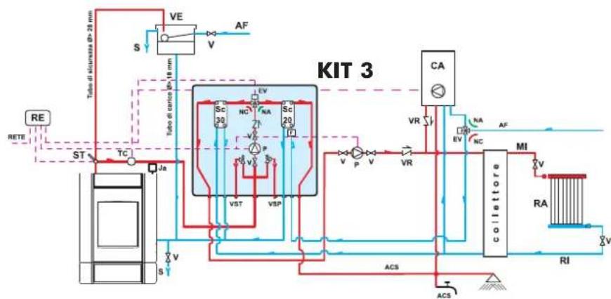
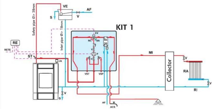
ACS: Hot Sanitary Water
AF: Cold Water
EV: 3-way Solenoid Valve
F: Flow Switch
MI: System Flow
NA: Normally Open
NC: Normally Closed
P: Pump (circulator)
RA: Radiators
RE: Electronic Regulator
RI: System Return
S: Drain
Sc 20: 20-plate Heat Exchanger
ST: Temperature Sensor
V: Valve
VE: Open Expansion Tank
VSP: 1.5 bar Pressurized Safety Valve
VST: Thermal Relief Valve
Ja: Automatic Relief Valve
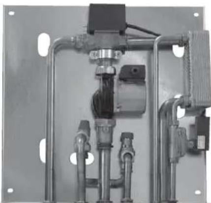
Kit 1 is designed to facilitate the work carried out by the installers. In fact, it consists of all the necessary components for the product to be properly installed.
NB: insulating mats must be applied so that the components of the kit are well-protected from the heat radiation emitted by the boiler-stoves.
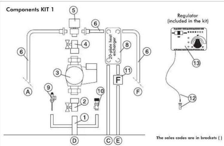
1 1" Male-Female Brass Collector
2 1" Ball Valve
3 Circulator with 1½" Fasteners (219660)
4 1" Check Valve (261910)
5 1" Male-Female 3-way Solenoid Valve (143330)
6 Copper Fittings
7 30-plate Heat Exchanger for heat transfer with the gas boiler circuit (216620)
8 20-plate Heat Exchanger for hot sanitary water production (205270)
9 3/4" Thermal Relief Valve (72940)
10 3/4" 1.5 bar Safety Valve (143260)
11 Flussostato (220830)
12 12 " Thermometer Well + Sensor (175960)
13 Electronic Regulator (220780)
A 3/4" System Return
B 3/4" System Flow
C 34 " Boiler-stoves Return
D 1" Boiler-stoves Flow
E 1/2" Cold Sanitary Water
F 1/2" Hot Sanitary Water
SELECTOR FUNCTIONS
Selector: OFF Everything is switched off
Selector: MAN Driven Circulator
Valve is set
Selector: AUTO Circulator is set
Valve is set
Alarm selection No acoustic signal in the
OFF position
natural_image
Industrial piping system mounted on a metal frame, no visible text or symbolsKIT 1
code 261880
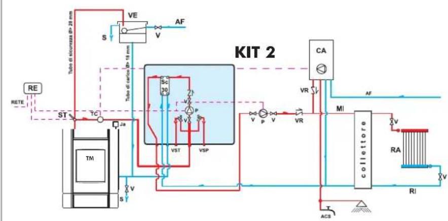
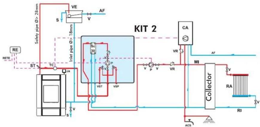
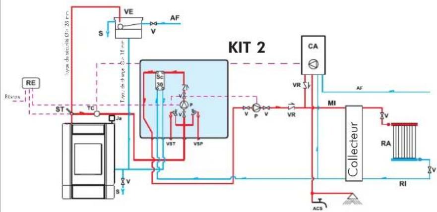
AN EXAMPLE OF A HYDRAULIC SYSTEM FOR A BOILER-STOVETHAT DOES NOT PRODUCE HOT SANITARY WATER BUT HAS A WALL MOUNTED BOILER
USING KIT 2
flowchart
graph TD
    A["RE"] --> B["ST"]
    B --> C["TC"]
    C --> D["Ja"]
    D --> E["S"]
    E --> F["VE"]
    F --> G["V"]
    G --> H["AF"]
    H --> I["Inlet pipe ∅ > 18mm"]
    I --> J["SC 30"]
    J --> K["VST"]
    K --> L["VSP"]
    L --> M["VA"]
    M --> N["P"]
    N --> O["V"]
    O --> P["VR"]
    P --> Q["CA"]
    Q --> R["MI"]
    R --> S["Collector"]
    S --> T["RA"]
    T --> U["RI"]
    U --> V["ACS"]
    V --> W["ACS"]
    W --> X["VA"]
    X --> Y["VR"]
    Y --> Z["CA"]
    Z --> AA["MI"]
    AA --> AB["Collector"]
    AB --> AC["RA"]
    AC --> AD["RI"]
    AD --> AE["ACS"]
AF: Cold Water
CA: Wall Mounted Boiler
MI: System Flow
P: Pump (circulator)
RA: Radiators
RE: Electronic Regulator
RI: System Return
S: Drain
Ja: Automatic Relief Valve
Sc 30: 30-plate Heat Exchanger
ST: Temperature Sensor
V: Valve
VE: Open Expansion Tank
VR: Check Valve
VSP: 1.5 bar Pressurized Safety Valve
VST: Thermal Relief Valve
Kit 2 is designed to facilitate the work carried out by the installers. In fact, it consists of all the necessary components for the product to be properly installed.
NB: insulating mats must be applied so that the components of the kit are well-protected from the heat radiation emitted by the boiler-stoves.
Components KIT 2
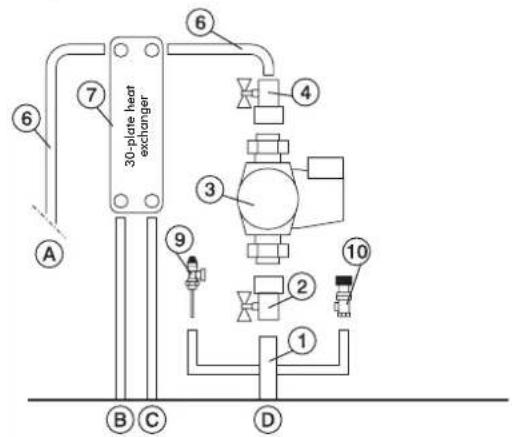
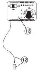
Regulator
(included in the kit)
The sales codes are in brackets ( )
1 1" Male-Female Brass Collector
2 1" Ball Valve
3 Circulator with 1½" Fasteners (219660)
4 1" Check Valve (261910)
5 1" Male-Female 3-way Solenoid Valve (143330)
6 Copper Fittings
7 30-plate Heat Exchanger for heat transfer with the gas boiler circuit (216620)
8 20-plate Heat Exchanger for hot sanitary water production (205270)
9 3/4" Thermal Relief Valve (72940)
10 3/4" 1.5 bar Safety Valve (143260)
11 Flow Switch (220830)
12 ½" Thermometer Well + Sensor (175960)
13 Electronic Regulator (220780)
A 3/4" System Return
B 3/4" System Flow
C 3/4" Boiler-stoves Return
D 1" Boiler-stoves Flow
E 1/2" Cold Sanitary Water
F 1/2" Hot Sanitary Water
Electrical Connections
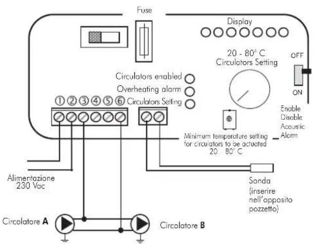
SELECTOR FUNCTIONS
Selector: OFF Everything is switched off
Selector: MAN Driven Circulator
Valve is set
Selector: AUTO Circulator is set
Valve is set
Alarm selection No acoustic signal in the
OFF position
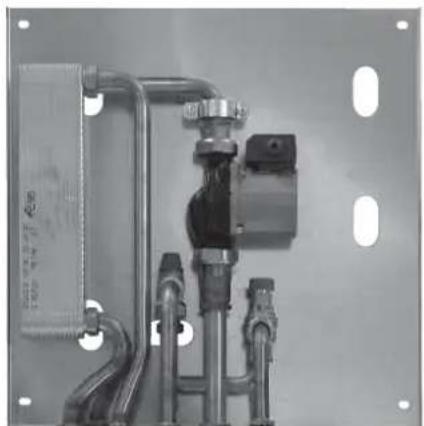
natural_image
Industrial piping system mounted on a metal frame, no visible text or symbolsKIT 2
code 261890
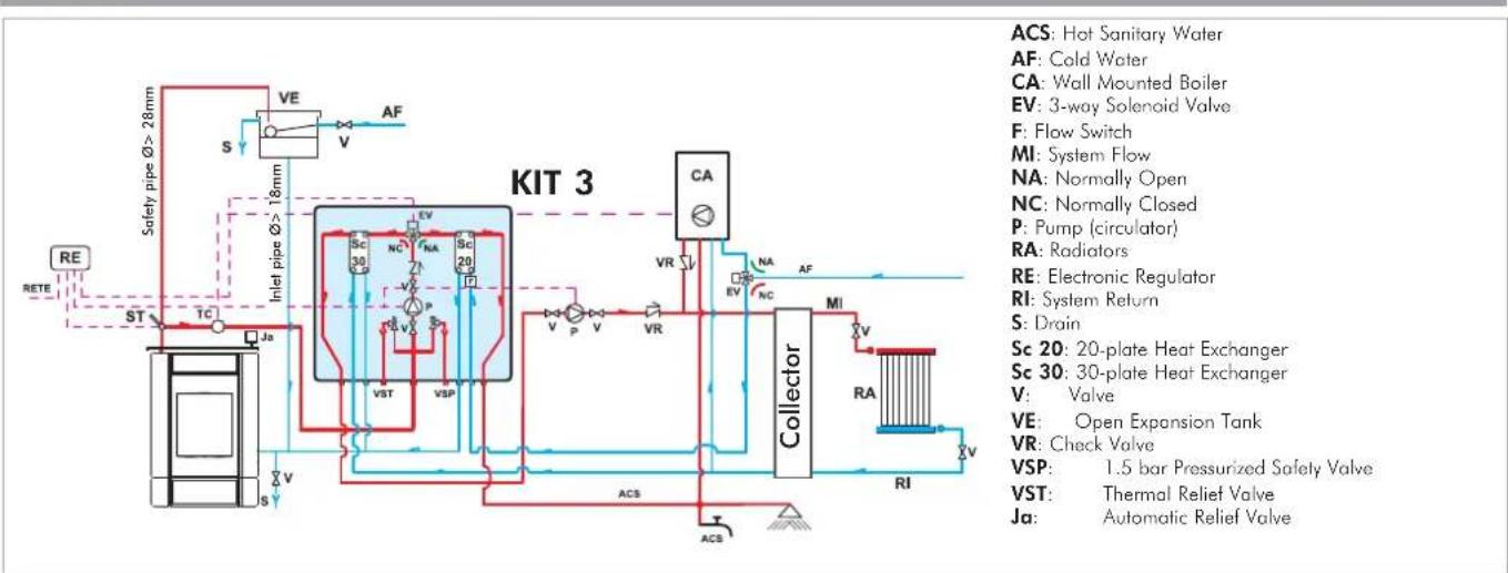
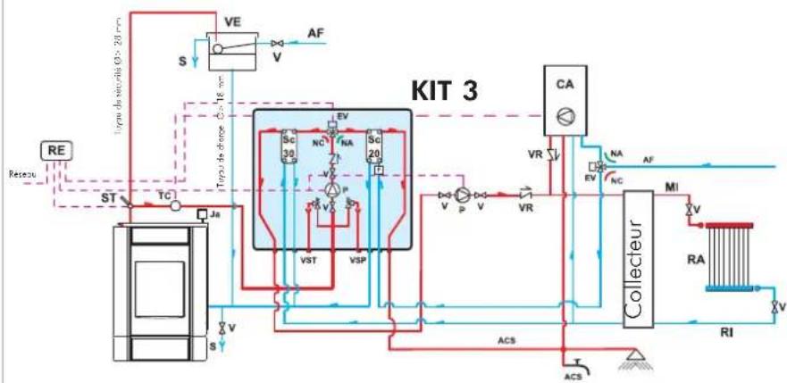
AN EXAMPLE OF A HYDRAULIC SYSTEM FOR A THERMO FIREPLACEITH HOT SANITARY WATER PRODUCTION AND A WALL MOUNTED BOILER
USING KIT 3
flowchart
graph TD
    A["RE"] --> B["ST"]
    B --> C["TC"]
    C --> D["Ja"]
    D --> E["S"]
    E --> F["VE"]
    F --> G["AF"]
    G --> H["VA"]
    H --> I["COLLECTOR"]
    I --> J["VA"]
    J --> K["RC"]
    K --> L["VA"]
    L --> M["ACS"]
    M --> N["Collector"]
    N --> O["VA"]
    O --> P["RC"]
    P --> Q["VA"]
    Q --> R["ACS"]
    R --> S["Collector"]
    S --> T["VA"]
    T --> U["ACS"]
    U --> V["Collector"]
    V --> W["VA"]
    W --> X["ACS"]
    X --> Y["Collector"]
    Y --> Z["VA"]
    Z --> AA["ACS"]
    AA --> AB["Collector"]
    AB --> AC["VA"]
    AC --> AD["ACS"]
    AD --> AE["Collector"]
    AE --> AF["VA"]
    AF --> AG["ACS"]
    AG --> AH["Collector"]
    AH --> AI["VA"]
    AI --> AJ["ACS"]
    AJ --> AK["Collector"]
    AK --> AL["VA"]
    AL --> AM["ACS"]
    AM --> AN["Collector"]
    AN --> AO["VA"]
    AO --> AP["ACS"]
    AP --> AQ["Collector"]
    AQ --> AR["VA"]
    AR --> AS["ACS"]
Kit 3 is designed to facilitate the work carried out by the installers. In fact, it consists of all the necessary components for the product to be properly installed.
NB: insulating mats must be applied so that the components of the kit are well-protected from the heat radiation emitted by the boiler-stoves.
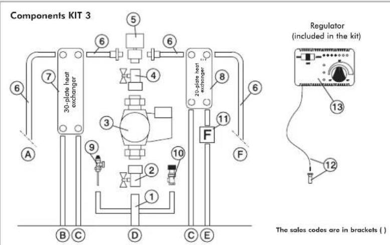
1" Male-Female Brass Collector
1" Ball Valve
2 Circulator with 1½" Fasteners (219660)
3 1" Check Valve (261910)
1" Male-Female 3-way Solenoid Valve (143330)
Copper Fittings
30-plate Heat Exchanger for heat transfer with
the gas boiler circuit
(216620)
20-plate Heat Exchanger for hot sanitary water production (205270)
9 3/4" Thermal Relief Valve (72940)
10 3/4" 1.5 bar Safety Valve (143260)
11 Flow Switch (220830)
12 1/6" Thermometer Well | Sensor (175960)
13 Electronic Regulator (220780)
A 3/4" System Return
B 3/4" System Flow
C 3/4" Boiler-stoves Return
D 1" Boiler-stoves Flow
E 1/2" Cold Sanitary Water
F 1/2" Hot Sanitary Water
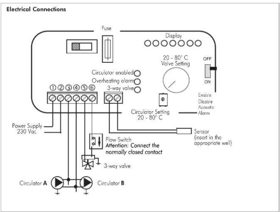
SELECTOR FUNCTIONS
Selector: OFF Everything is switched off
Selector: MAN Driven Circulator
Valve is set
Selector: AUTO Circulator is set
Valve is set
Alarm selection No acoustic signal in the
OFF position
natural_image
Industrial piping and valve assembly with no visible text or symbolsKIT 3
code 261900
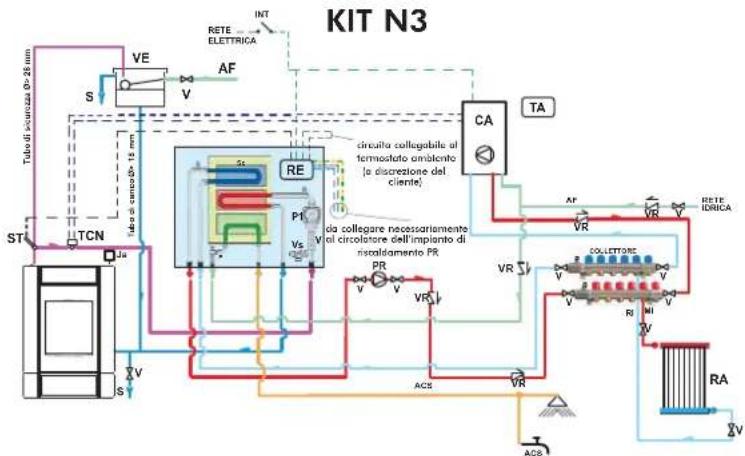
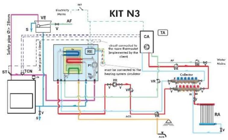
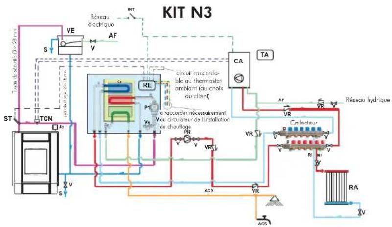
AN EXAMPLE OF A HYDRAULIC SYSTEM FOR A THERMO FIREPLACEITH HOT SANITARY WATER PRODUCTION AND A WALL MOUNTED BOILER
USING
KIT N3
flowchart
graph TD
    A["Safety pipe Ø >28mm"] --> B["TCN"]
    B --> C["PT"]
    C --> D["RE"]
    D --> E["CA"]
    E --> F["Collector"]
    F --> G["Water Main"]
    H["ACS"] --> I["RA"]
    J["VR"] --> K["PA"]
    L["VA"] --> M["VA"]
    N["VA"] --> O["VA"]
    P["VA"] --> Q["VA"]
    R["VA"] --> S["VA"]
    T["VA"] --> U["VA"]
    V["VA"] --> W["VA"]
    X["VA"] --> Y["VA"]
    Z["VA"] --> AA["VA"]
    AB["S"] --> AC["VE"]
    AD["S"] --> AE["V"]
    AF["AF"] --> AG["V"]
    AH["INT"] --> AI["RC"]
    AJ["SA"] --> AK["PE"]
    AL["SA"] --> AM["PE"]
    AN["SA"] --> AO["PE"]
    AP["SA"] --> AQ["PE"]
    AR["SA"] --> AS["PE"]
    AT["SA"] --> AU["PE"]
    AV["SA"] --> AW["PE"]
    AX["SA"] --> AY["PE"]
    AZ["SA"] --> BA["PE"]
    BB["SA"] --> BC["PE"]
    BD["SA"] --> BE["PE"]
    BF["SA"] --> BG["PE"]
    BH["SA"] --> BI["PE"]
    BJ["SA"] --> BK["PE"]
    BL["SA"] --> BM["PE"]
    BN["SA"] --> BO["PE"]
    BP["SA"] --> BQ["PE"]
    BR["SA"] --> BS["PE"]
    BT["SA"] --> BU["PE"]
    BV["SA"] --> BW["PE"]
    BX["SA"] --> BY["PE"]
    BZ["SA"] --> CA["PE"]
    CB["SA"] --> CC["PE"]
    DD["SA"] --> DE["PE"]
    DF["SA"] --> DG["PE"]
    DH["SA"] --> DI["PE"]
    DJ["SA"] --> DK["PE"]
    DL["SA"] --> DM["PE"]
    DN["SA"] --> DO
    DO --> DO
    DO --> DR["TA"]
    DO --> DV["TA"]
    DO --> DW["TA"]
    DO --> DX["TA"]
    DO --> DXT["TA"]
CA: Wall Mounted Boiler
PR: Pump (circulator)
P1: Primary circuit pump
RE: Electronic regulator
TA: Room thermostat
VE: Expansion Tank
Ja: Air refief Valve
V: Intercept valve
VR: Retaining valve
ST: Temperature Sensor
F: Flow switch
Sc: Heat plate exchanger
EV: 3-way solenoid valve
RI: Heating system return
RA: Radiators
MI: Heating system flow
AF: Cold water
ACS: Hot sanitary water
S: Drain
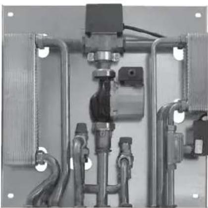
Kit N3 is designed to facilitate the work carried out by the installers. In fact, it consists of all the necessary components for the product to be properly installed.
NB: insulating mats must be applied so that the components of the kit are well-protected from the heat radiation emitted by the boiler-stoves.
Components KIT N3
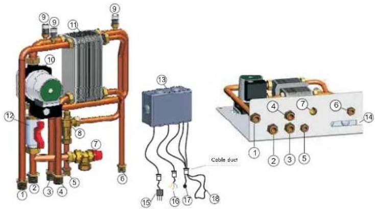
1 Heating system return G 3/4"
2 EDILKAMIN generator flow G 3/4"
3 EDILKAMIN generator return G 3/4"
4 Heating system flow G 3/4"
5 Cold sanitary water inlet G 1/2"
6 Hot water return to the sanitary system G 1/2"
7 Safety valve - temperature and pressure (90 °C - 3bar)
8 Flow Switch
9 Air relief valve G 3/8"
10 EDILKAMIN generator circuit circulator
11 3-way heat exchanger
12 Intercept valve G 1"
13 Electronic regulator with wiring
14 Appropriate aperture for the cable duct to pass through
15 Power cable
16 Cables for the heating system circulator (phase, neutral, earth)
17 Temperature sensor
18 Room thermostat circuit
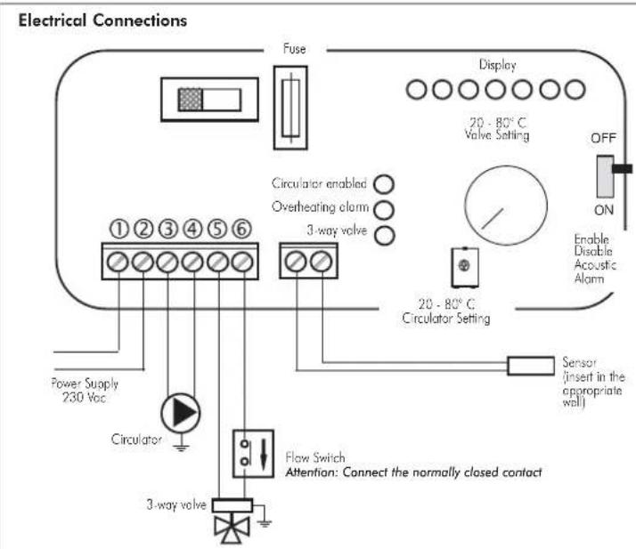
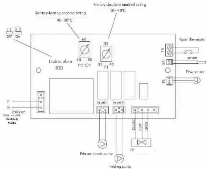
Electrical Connections

natural_image
Technical diagram of a heat exchanger system with pipes, valves, and control panel (no text or labels)KIT N3
code 627690
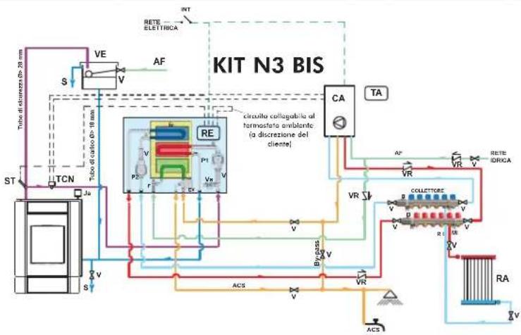
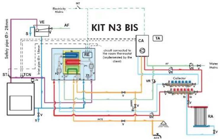
AN EXAMPLE OF A HYDRAULIC SYSTEM FOR A BOILER-STOVEWITH HOT SANITARY WATER PRODUCTION AND A WALL MOUNTED BOILER
USING KIT N3 BIS
flowchart
graph TD
    A["Safety pipes Ø > 28mm"] --> B["VE"]
    B --> C["AF"]
    C --> D["RE"]
    D --> E["CA"]
    E --> F["TA"]
    F --> G["Collector"]
    G --> H["V"]
    G --> I["V"]
    G --> J["V"]
    G --> K["V"]
    G --> L["V"]
    G --> M["V"]
    G --> N["V"]
    G --> O["V"]
    G --> P["V"]
    G --> Q["V"]
    G --> R["V"]
    G --> S["V"]
    G --> T["V"]
    G --> U["V"]
    G --> V["V"]
    G --> W["V"]
    G --> X["V"]
    G --> Y["V"]
    G --> Z["V"]
    G --> AA["V"]
    G --> AB["V"]
    G --> AC["V"]
    G --> AD["V"]
    G --> AE["V"]
    G --> AF["V"]
    G --> AG["V"]
    G --> AH["V"]
    G --> AI["V"]
    G --> AJ["V"]
    G --> AK["V"]
    G --> AL["V"]
    G --> AM["V"]
    G --> AN["V"]
    G --> AO["V"]
    G --> AP["V"]
    G --> AQ["V"]
    G --> AR["V"]
    G --> AS["V"]
    G --> AT["V"]
    G --> AU["V"]
    G --> AV["V"]
CA Wall Mounted Boiler
P2 Pump (circulator)
P1 Primary circuit pump
RE Electronic regulator
TA Room Thermostat
VE Expansion Tank
Ja Air Relief Valve
V Intercept valve
VR Retaining valve
ST Temperature Sensor
F Flow switch
Sc Heat Plate Exchanger
EV 3-way Solenoid Valve
RI Heating system return
RA Radiators
MI Heating system flow
AF Cold Water
ACS Hot Sanitary Water
S Drain
INT Main switch
TCN Contact Thermostat
Kit N3 BIS is designed to facilitate the work carried out by the installers. In fact, it consists of all the necessary components for the product to be properly installed.
NB: insulating mats must be applied so that the components of the kit are well-protected from the heat radiation emitted by the boiler-stoves.
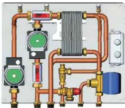
Components KIT N3 BIS
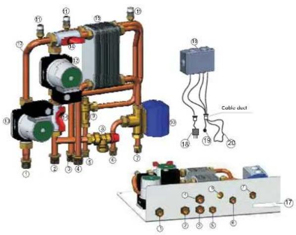
1 Heating system return G 3/4"
2 EDILKAMIN generator flow G 3/4"
3 EDILKAMIN generator return G 3/4"
4 Heating system flow G 3/4"
5 Cold sanitary water inlet G 1/2"
6 Hot water return to the sanitary system G 1/2"
7 Sanitary hot water inlet to the gas boiler G 1/2"
8 Safety valve - temperature and pressure (90 °C - 3bar)
9 Flow Switch
10 3-way deviation solenoid valve
11 Air relief valve G 3/8"
12 EDILKAMIN generator circuit circulator
13 Heating system circuit circulator
14 Intercept valve G 1"
15 3-way heat exchanger
16 Electronic regulator with wiring
17 Appropriate aperture for the cable duct to pass through
18 Power cable
19 Temperature sensor
20 Room thermostat circuit
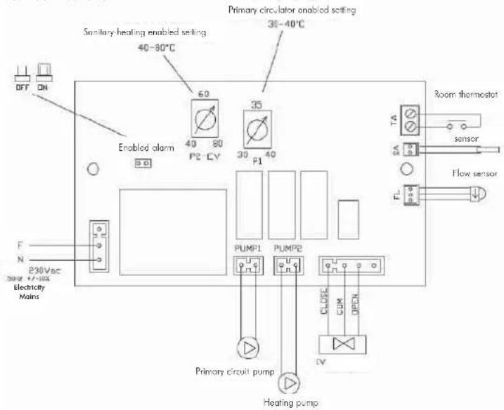
Electrical Connections
natural_image
Pure electrical circuit lines without any symbolsKIT N3 BIS
code 627860
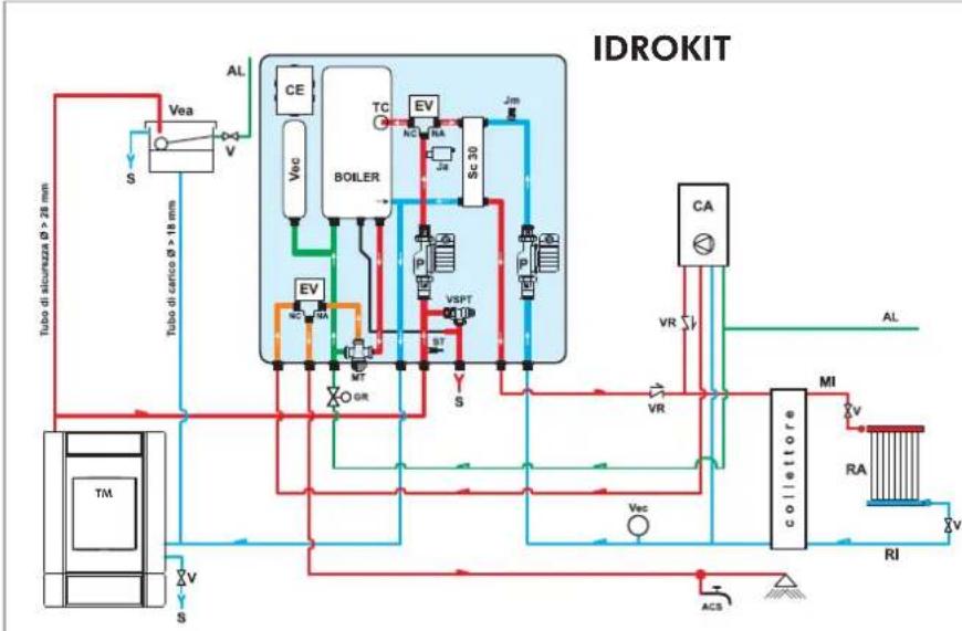
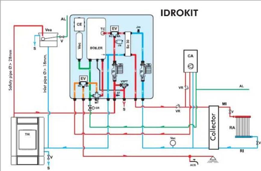
AN EXAMPLE OF A HYDRAULIC SYSTEM FOR A BOILER-STOVETHAT PRODUCES AND STORES HOT SANITARY WATER AND HAS A WALL MOUNTED BOILER
USING IDROKIT
flowchart
graph TD
    A["Safety pipe Ø > 28mm"] --> B["Vea"]
    B --> C["VEa"]
    C --> D["Boiler"]
    D --> E["TC"]
    E --> F["EV"]
    F --> G["Sc 30"]
    G --> H["VA"]
    H --> I["CA"]
    I --> J["Collector"]
    J --> K["MI"]
    K --> L["RA"]
    L --> M["RI"]
    M --> N["ACS"]
    N --> O["Valve"]
    O --> P["VR"]
    P --> Q["Valve"]
    Q --> R["VO"]
    R --> S["Valve"]
    S --> T["Valve"]
    T --> U["Valve"]
    U --> V["Valve"]
    V --> W["Valve"]
    W --> X["Valve"]
    X --> Y["Valve"]
    Y --> Z["Valve"]
    Z --> AA["Valve"]
    AA --> AB["Valve"]
    AB --> AC["Valve"]
    AC --> AD["Valve"]
    AD --> AE["Valve"]
    AE --> AF["Valve"]
    AF --> AG["Valve"]
    AG --> AH["Valve"]
    AH --> AI["Valve"]
    AI --> AJ["Valve"]
    AJ --> AK["Valve"]
    AK --> AL["Valve"]
    AL --> AM["Valve"]
    AM --> AN["Valve"]
    AN --> AO["Valve"]
    AO --> AP["Valve"]
    AP --> AQ["Valve"]
    AQ --> AR["Valve"]
    AR --> AS["Valve"]
    AS --> AT["Valve"]
    AT --> AU["Valve"]
    AU --> AV["Valve"]
ACS: Hot Sanitary Water
AF: Cold Water
AL: Water Mains Supply
C: Filling/Top-Up Section
CE: Electronic Panel
EV: 3-way Solenoid Valve
NA: Normally Open
NC: Normally Closed
GR: Pressure Reducer
Ja: Automatic Relief Valve
Jm: Manual Relief Valve
MI: System Flow
MT: Thermostatic Mixer
P: Pump (circulator)
RA: Radiators
RI: System Return
S: Drain
SC30: 30-plate Heat Exchanger
ST: Temperature Sensor
TC: Contact Thermostat
TM: Thermo Boiler-stoves
V: Ball Valve
Vea: Open Expansion Tank
Vec: Closed Expansion Tank
VR: Check Valve
VSPT: Safety Pressure and Temperature Valve
VCA: Boiler
IDROKIT is designed to facilitate the work carried out by the installers. In fact, it consists of all the necessary components for the product to be properly installed.

1 heating return
2 gas boiler hot sanitary water
3 boiler-stoveflow
4 drain
5 hot sanitary water
6 boiler-stovereturn
7 heating flow
8 water mains
9 thermostatic mixer setting
10 synoptic panel
11 auxiliary socket for a room thermostat
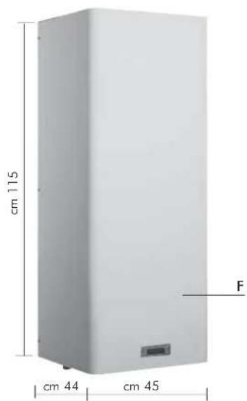
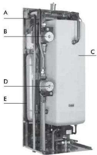
A 30-plate Heat Exchanger
B primary circulator (in the wood-fired version)
C 50-litre boiler
D heating system circulator
E closed expansion tank
F boiler-stoves covering for exposed installation
IDROKIT
code 601740
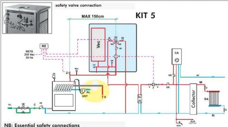
AN EXAMPLE OF A HYDRAULIC SYSTEM FOR A THERMO BOILER-STOVES - ONLY HEATING
USING KIT 5
flowchart
graph TD
    A["RETE 230 Vac 50 Hz"] --> B["Max"]
    B --> C["VEc"]
    C --> D["NC"]
    C --> E["P"]
    C --> F["VR"]
    C --> G["VA"]
    C --> H["VA"]
    C --> I["VA"]
    C --> J["VA"]
    C --> K["VA"]
    C --> L["VA"]
    C --> M["VA"]
    C --> N["VA"]
    C --> O["VA"]
    C --> P["VA"]
    C --> Q["VA"]
    C --> R["VA"]
    C --> S["VA"]
    C --> T["VA"]
    C --> U["VA"]
    C --> V["VA"]
    C --> W["VA"]
    C --> X["VA"]
    C --> Y["VA"]
    C --> Z["VA"]
    C --> AA["VA"]
    C --> AB["VA"]
    C --> AC["VA"]
    C --> AD["VA"]
    C --> AE["VA"]
    C --> AF["VA"]
    C --> AG["VA"]
    C --> AH["VA"]
    C --> AI["VA"]
    C --> AJ["VA"]
    C --> AK["VA"]
    C --> AL["VA"]
    C --> AM["VA"]
    C --> AN["VA"]
    C --> AO["VA"]
    C --> AP["VA"]
    C --> AQ["VA"]
    C --> AR["VA"]
    C --> AS["VA"]
    C --> AT["VA"]
    C --> AU["VA"]
    C --> AV["VA"]
    C --> AW["VA"]
    C --> AX["VA"]
    C --> AY["VA"]
    C --> AZ["VA"]
    C --> BA["VA"]
    C --> BB["VA"]
    C --> BC["VA"]
    C --> BD["VA"]
    C --> BE["VA"]
    C --> BF["VA"]
    C --> BG["VA"]
    C --> BH["VA"]
    C --> BI["VA"]
    C --> BJ["VA"]
    C --> BK["VA"]
    C --> BL["VA"]
    C --> BM["VA"]
    C --> BN["VA"]
    C --> BO["VA"]
    C --> BP["VA"]
    C --> BQ["VA"]
    C --> BR["VA"]
    C --> BS["VA"]
    C --> BT["VA"]
    C --> BU["VA"]
    C --> BV["VA"]
    C --> BW["VA"]
    C --> BX["VA"]
    C --> BY["VA"]
    C --> BZ["VA"]
    C --> CA["VA"]
    C --> CB["VA"]
    C --> CC["VA"]
    C --> CD["VA"]
    C --> CE["VA"]
    C --> CF["VA"]
    C --> CG["VA"]
    C --> CH["VA"]
    C --> CI["VA"]
    C --> CJ["VA"]
    C --> CK["VA"]
    C --> CL["VA"]
    C --> CM["VA"]
    C --> CN["VA"]
    C --> CO["VA"]
    C --> CP["VA"]
    C --> CZ["VA"]
    C --> DA["VA"]
    C --> DB["VA"]
    C --> DC["VA"]
    C --> DD["VA"]
    C --> DE["VA"]
    C --> DF["VA"]
    C --> DG["VA"]
    C --> DH["VA"]
    C --> DI["VA"]
    C --> DJ["VA"]
    C --> DK["VA"]
    C --> DL["VA"]
    C --> DV["VA"]
    C --> DW["VA"]
AL: Water Mains Supply
C: Filling/Top-Up Section
EV: 3-way Solenoid Valve
NA: Normally Open
NC: Normally Closed
GR: Filling unit
Ja: Automatic Relief Valve
Jm: Manual Relief Valve
MAN: Manometer
MI: System Flow
P: Pump (circulator)
RA: Radiators
RE: Electronic Regulator
RI: System Return
S: Drain
ST: Temperature Sensor
V: Ball Valve
Vec: Closed Expansion Tank
VR: Check Valve
VSP: Pressurised Safety Valve
VST: Thermal Relief Valve
Kit 5 is designed to facilitate the work carried out by the installers. In fact, it consists of all the necessary components for the product to be properly installed.
NB: insulating mats must be applied so that the components of the kit are well protected from the heat radiation emitted by the boiler-stoves.
Components KIT 5
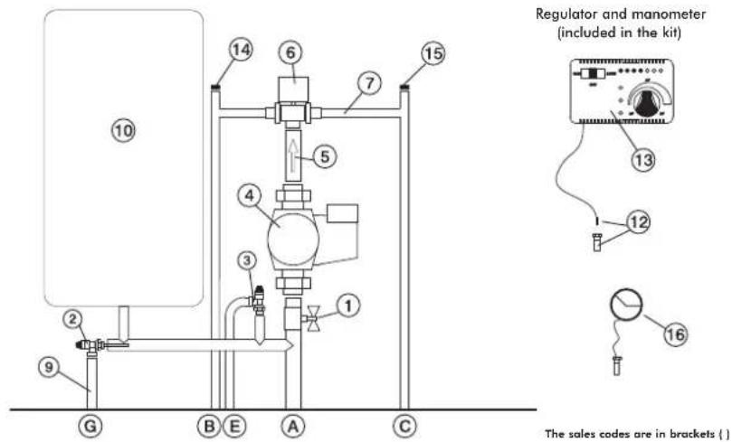
1 1" Ball Valve
2 Thermal Relief Valve (72940)
3 Pressure Relief Valve (284220)
4 Circulator (219660)
5 Fittings with 1" Check Valve (284180)
6 3/4" Male 3-way Solenoid Valve (283690)
7 Fittings
9 Temperature Relief Valve Nozzle
10 Closed Expansion Tank (283680)
12 1/2" Thermometer Well + Sensor (175960)
13 Electronic Regulator (220780)
14 3/8" Automatic Relief Valve (284150)
15 1/4" Manual Relief Valve (284170)
16 Manometer (269590)
A Boiler-stoves Flow
B System return
c Boiler-stoves Return
E Pressure Relief Valve
G Temperature Relief Valve
Electrical Connections
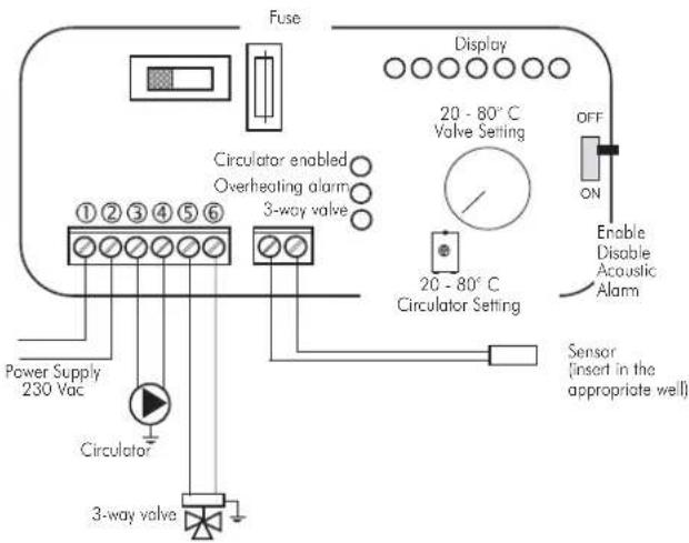
SELECTOR FUNCTIONS
Selector: OFF Everything is switched off
Selector: MAN Driven Circulator
Valve is set
Selector: AUTO Circulator is set
Valve is set
Alarm selection No acoustic signal in the
OFF position
natural_image
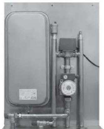
Industrial piping and valve assembly (no visible text or symbols)KIT 5
code 280590
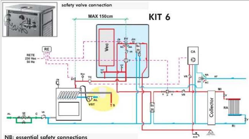
AN EXAMPLE OF A HYDRAULIC SYSTEM FOR A BOILER-STOVEWITH HOT SANITARY WATER PRODUCTION
USING KIT 6
flowchart
graph TD
    A["RETE 230 Vac 50 Hz"] --> B["Valve"]
    B --> C["Switch"]
    C --> D["Valve"]
    D --> E["Collector"]
    E --> F["RA"]
    E --> G["RI"]
    E --> H["MI"]
    H --> I["Collector"]
    I --> J["VA"]
    I --> K["VR"]
    I --> L["SC 30"]
    L --> M["Valve"]
    M --> N["Switch"]
    N --> O["Valve"]
    O --> P["Collector"]
    P --> Q["VA"]
    P --> R["VR"]
    P --> S["SC 20"]
    S --> T["Valve"]
    T --> U["Switch"]
    U --> V["Valve"]
    V --> W["Collector"]
    W --> X["VA"]
    W --> Y["VR"]
    W --> Z["SC 30"]
    Z --> AA["Valve"]
    AA --> AB["Switch"]
    AB --> AC["Valve"]
    AC --> AD["Collector"]
    AD --> AE["VA"]
    AD --> AF["VR"]
    AD --> AG["SC 20"]
    AG --> AH["Valve"]
    AH --> AI["Switch"]
    AI --> AJ["Valve"]
    AJ --> AK["Collector"]
    AK --> AL["VA"]
    AK --> AM["VR"]
ACS: Hot Sanitary Water
AF: Cold Water
AL: Water Mains Supply
C: Filling/Top-Up Section
EV: 3-way Solenoid Valve
NA: Normally Open NC: Normally Cl
NC: Normally Closed
F: Flow Switc
GR: Filling unit
Ja: Automatic Relief Valve
Jm: Manual Relief Valve
MAN: Manometer
MI: System Flow
P: Pump (circulator)
RA: Radiators
RE: Electronic Regulator
RI: System Return
S: Drain
SC: Plate Exchanger
ST: Temperature Sensor
V: Ball Valve
Vec: Closed Expansion Tank
VR: Check Valve
VSP: Pressurised Safety Valve
VST: Thermal Relief Valve
NB: insulating mats must be applied so that the components of the kit are well protected from the heat radiation emitted by the boiler-stoves.
Kit 6 is designed to facilitate the work carried out by the installers. In fact, it consists of all the necessary components for the product to be properly installed.
Componenti KIT 6
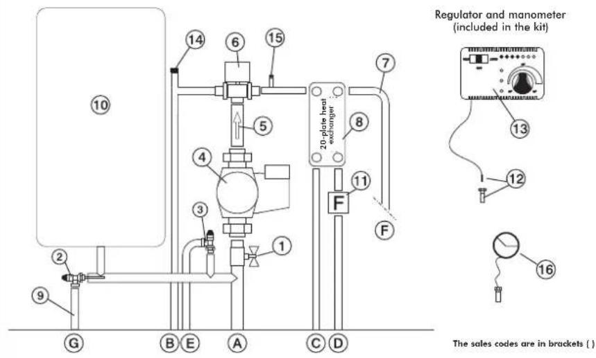
1 Ball Valve
2 Thermal Relief Valve (72940)
3 Pressure Relief Valve (284220)
4 Circulator (219660)
5 Fittings with 1" Check Valve (284180)
6 3/4" Male 3-way Solenoid Valve (283690)
7 Fittings
8 20-plate Heat Exchanger for hot sanitary water production (284300)
9 Temperature Relief Valve Nozzle
10 Closed Expansion Tank (283680)
11 Flow Switch (220830)
12 1/2" Thermometer Well + Sensor (175960)
13 Electronic Regulator (220780)
14 3/8" Automatic Relief Valve (284150)
15 1/4" Manual Relief Valve (284170)
16 Manometer (269590)
A Boiler-stoves Return
B System Return
C Boiler-stoves Return
D Cold Sanitary Water
E Pressure Relief Valve
F Hot Sanitary Water
G Temperature Relief Valve
Selector: OFF Everything is switched off
Selector: MAN Driven Circulator
Valve is set
Selector: AUTO Circulator is set
Valve is set
Alarm selection No acoustic signal in the
OFF position
SELECTOR FUNCTIONS
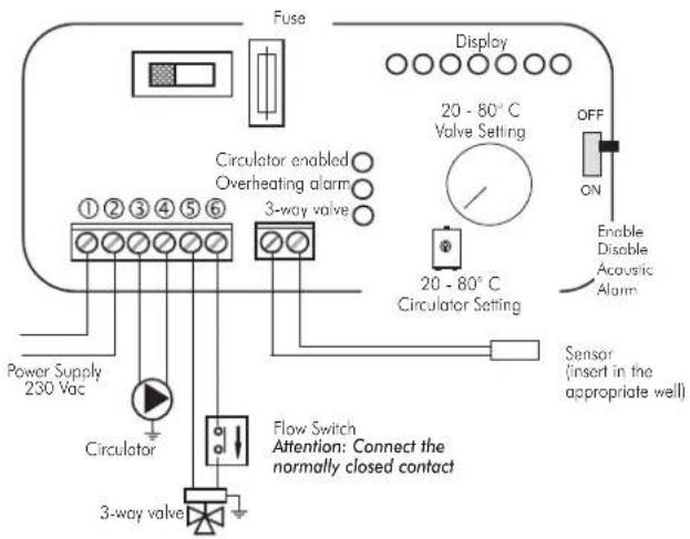
Electrical Connections
natural_image
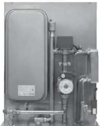
Industrial equipment setup with pressure vessel, pipes, and control panel (no visible text or symbols)KIT 6
code 280600
electronic regulator
IMPORTANT ADVICE REGARDING THE INSTALLATION
The connections, commissioning and verification of proper operation of the boiler-stoves must be carried out by qualified personnel, who can implement all connections in accordance with the laws in force, particularly with Italian Law No. 46/90, apart from complying with these instructions.
Compliance with regulations regarding the earth connection is fundamental for the safety of people.
It is obligatory to install a differential circuit breaker switch before the device and the entire electrical circuit of the thermo boiler-stoves. It is also obligatory to connect the pump, valve and metal parts of the boiler-stove to an earthing system.
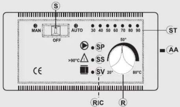
LEGEND
AA acoustic alarm switch
R way valve opening setting (KITS 1-3-5-6)
R circulators operation setting (KIT 2)
RIC internal pump setting
S MAN-OFF-AUTO selector
SP pump light
SS overheating light
ST temperature scale
SV 3-way valves light (KITS 1-3-5-6)
SV circulators setting (KIT 2)
fig. M
| Technical Data | |
| Power Supply (+15 – 10%) Vac 230 | |
| Degree of protection IP 40 | |
| Min/Max Room Temperature °C 0 to+50 | |
| Sensor range m 1,2 | |
| Thermometer °C 30 to 90 | |
| Maximum contact rating of the circulator W 400 | |
| Maximum contact rating of the 3-way valve W | 250 |
| Fuse mA | 500 |
The electric control regulator allows you to monitor the operating conditions and is equipped with:
- MAN-OFF-AUTO selector (S)
- temperature scale (ST)
- acoustic alarm (AA)
- 3-way valve opening setting (R) (KIT1-3)
- circulators operation setting (R) (KIT2)
- internal pump setting (RIC)
- 3-way valve light (SV) (KIT1-KIT3)
- circulators setting light (SV) (KIT2)
- overheating pump (SS)
- pump light (SP)
Operation
- Control device:
- Thermometer
- Protection device
(acoustic alarm system):
• Acoustic alarm (AA)
• Overheating alarm (SS)
This system intervenes when the water temperature exceeds 90^ C and warns the user to stop adding fuel.
The acoustic alarm can be disabled from the switch (AA).
However, the alarm remains enabled by means of the
overheating light (SS).
To restore the initial settings, the switch (AA) must be enabled after the water temperature in the boiler-stovehas cooled down.
- Power supply device (circulation system):
• MAN-OFF-AUTO selector (S)
- Pump light (SP)
The pump remains on when in manual mode and off when in
OFF mode. When in AUTO mode, the pump is activated by the system when the desired temperature is reached, by means of the internal setting (RIC), which ranges from 20 to 80°C (this is pre-set at 20°C).
- Operation device (setting system):
• 3-way valve opening setting (R)
• 3-way valve operating light (SV)
When the fluid reaches the temperature set through the regulator, the 3-way valve diverts the fluid to the radiators and the operating light (SV) goes on.
When the temperature of the fluid drops below the set value, the system opens the electrical circuit and the 3-way valve bypasses the fluid directly to the boiler-stove.
Attention:
During normal operation check that the warning lights (SV) and (SP) are lit.
Positioning
The electronic regulator must be installed close to the thermo boiler-stoves. The sensor of the operation, protection and control devices must be placed directly on the boiler-stoveor at most on the flow pipe, no more than 5 cm away from the boiler-stoveand in any case before any intercepting device. The sensor must be immersed in the well.
Installation
Follow this procedure to install the electronic regulator correctly: loosen the fastening screw, remove the cover and fasten it in place against the wall with the dowels supplied.
Then make the connections, paying utmost attention to the wiring diagram and pass the wires through ducts that are in conformity with the regulations in force. Put the cover back in place and tighten the screw.
The power supply must be disconnected from the mains and the AUTO-OFF-MAN selector (S) must be in the OFF position when all these operations are carried out.
Connect the brown wire (phase) and blue wire (neutral) of the 3-way Valve, respectively, to terminals 5 and 6 of the regulator.
Connect the yellow/green wire to the earth
Follow the assembly instructions contained in the package to connect the regulator to the system properly.
Madame, Monsieur,
UN ALLUMAGE "À SEC" RISQUE D'ENDOMMAGER LE THERMOPOÊLE.
DÉCLARATION DE CONFORMITÉ
2006/95/CEE - Directive Basse Tension
natural_image
Exterior view of a modern outdoor stove with visible flames and ventilation grilles (no text or symbols)KLIMA BASE

natural_image
Exterior view of a modern electric stove with visible flames and ventilation grilles (no text or symbols)WARM BASE
natural_image
Exterior view of a modern outdoor stove with visible flames and ventilation grilles (no text or symbols)natural_image
Modern portable stove with visible flame inside, no text or symbols presentnatural_image
Close-up of a hand holding a screwdriver inserted into a metal component, with no visible text or symbols.BY-PASS FUMÉES AUTOMATIQUE
natural_image
Close-up of a mechanical joint or bracket with a metallic component and a curved arrow indicating direction (no text or symbols visible)FERMETURE AUTOMATIQUE PORTE
natural_image
Technical line drawing of a vertical industrial structure with a blue component mounted on a cabinet (no text or symbols)2
3
4
• CONDUIT DES FUMÉES
natural_image
Two vertical panels with dot patterns, one empty and one with dashed alignment markers (no text or symbols)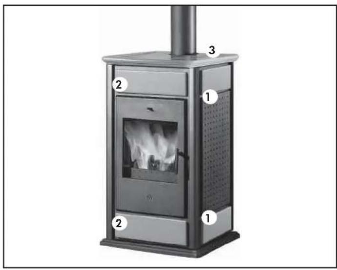
SET CÉRAMIQUES
WARM / KLIMA BASE
SET CÉRAMIQUES
natural_image
Industrial piping system mounted on a metal frame, no visible text or symbolsKIT 1
code 261880
EXEMPLE DE SYSTÈME HYDRAULIQUE POUR THERMOPOÈLES SANS PRODUCTION D'EAU CHAUDE SANITAIRE + CHAUDIÈRE MURALE
AVEC UTILISATION DU
KIT 2
flowchart
graph TD
    A["RE"] --> B["ST"]
    B --> C["TC"]
    C --> D["Ja"]
    D --> E["V"]
    E --> F["S"]
    F --> G["VE"]
    G --> H["V"]
    H --> I["AF"]
    I --> J["CA"]
    J --> K["MI"]
    K --> L["Collecteur"]
    L --> M["RA"]
    M --> N["RI"]
    N --> O["V"]
    O --> P["ACS"]
    P --> Q["VST"]
    Q --> R["VSP"]
    R --> S["SC"]
    S --> T["30V"]
    T --> U["V"]
    U --> V["VR"]
    V --> W["VR"]
    W --> X["PA"]
    X --> Y["VA"]
    Y --> Z["VR"]
    Z --> AA["CA"]
    AA --> AB["AF"]
    AB --> AC["KIT 2"]
AF: Eau Froide
CA: Chaudière murale
natural_image
Industrial piping system with valves and a control panel (no visible text or symbols)KIT 2
code 261890
EXEMPLE DE SYSTÈME HYDRAULIQUE POUR THERMOPOÈLES AVEC PRODUCTION D'EAU CHAUDE SANITAIRE + CHAUDIÈRE MURALE
AVEC UTILISATION DU
KIT 3
flowchart
graph TD
    A["RE"] --> B["ST"]
    B --> C["TC"]
    C --> D["Ja"]
    D --> E["VST"]
    E --> F["VSP"]
    F --> G["VA"]
    G --> H["SC 20"]
    H --> I["CA"]
    I --> J["Collecteur"]
    J --> K["MI"]
    K --> L["RA"]
    L --> M["RI"]
    M --> N["ACS"]
    N --> O["ACS"]
    O --> P["VST"]
    P --> Q["VSP"]
    Q --> R["VA"]
    R --> S["SC 20"]
    S --> T["CA"]
    T --> U["Collecteur"]
    U --> V["MI"]
    V --> W["RA"]
    W --> X["RI"]
    X --> Y["ACS"]
    Y --> Z["VST"]
    Z --> AA["VSP"]
    AA --> AB["VA"]
    AB --> AC["SC 20"]
    AC --> AD["CA"]
    AD --> AE["Collecteur"]
    AE --> AF["MI"]
    AF --> AG["RA"]
    AG --> AH["RI"]
    AH --> AI["ACS"]
natural_image
Industrial piping system with valves and valves mounted on a metal frame (no visible text or labels)KIT 3
code 261900
EXEMPLE DE SYSTÈME HYDRAULIQUE POUR THERMOPOÉLES AVEC PRODUCTION D'EAU CHAUDE SANITAIRE + CHAUDIÈRE MURALE AVEC UTILISATION DU
KIT N3
flowchart
graph TD
    A["TCN"] -->|S| B["VE"]
    B -->|V| C["RE"]
    C --> D["CA"]
    D --> E["TA"]
    E --> F["Résseau hydrique"]
    F --> G["Collecteur"]
    G --> H["RA"]
    H --> I["V"]
    C --> J["VA"]
    C --> K["VR"]
    C --> L["ACS"]
    C --> M["ACS"]
    C --> N["VA"]
    style A fill:#f9f,stroke:#333
    style B fill:#ccf,stroke:#333
    style C fill:#cfc,stroke:#333
    style D fill:#fcc,stroke:#333
    style E fill:#cff,stroke:#333
    style F fill:#ffc,stroke:#333
    style G fill:#cfc,stroke:#333
    style H fill:#fcc,stroke:#333
    style I fill:#cfc,stroke:#333
    style J fill:#cfc,stroke:#333
    style K fill:#cfc,stroke:#333
    style L fill:#cfc,stroke:#333
    style M fill:#cfc,stroke:#333
CA: Chaudière murale
natural_image
Technical diagram of a heat exchanger system with pipes, valves, and control panel (no text or labels)KIT N3
code 627690
EXEMPLE DE SYSTÈME HYDRAULIQUE POUR THERMOPOÈLES AVEC PRODUCTION D'EAU CHAUDE SANITAIRE + CHAUDIÈRE MURALE
AVEC UTILISATION DU
KIT N3 BIS
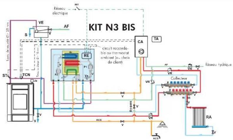
flowchart
graph TD
    A["ST"] --> B["TCN"]
    B --> C["VE"]
    C --> D["AF"]
    D --> E["CA"]
    E --> F["Collecteur"]
    F --> G["RA"]
    G --> H["ACS"]
    H --> I["BYPASS"]
    I --> J["VA"]
    J --> K["VA"]
    K --> L["VA"]
    L --> M["VA"]
    M --> N["VA"]
    N --> O["VA"]
    O --> P["VA"]
    P --> Q["VA"]
    Q --> R["VA"]
    R --> S["VA"]
    S --> T["VA"]
    T --> U["VA"]
    U --> V["VA"]
    V --> W["VA"]
    W --> X["VA"]
    X --> Y["VA"]
    Y --> Z["VA"]
    Z --> AA["VA"]
    AA --> AB["VA"]
    AB --> AC["VA"]
    AC --> AD["VA"]
    AD --> AE["VA"]
    AE --> AF["VA"]
    AF --> AG["VA"]
    AG --> AH["VA"]
    AH --> AI["VA"]
    AI --> AJ["VA"]
    AJ --> AK["VA"]
    AK --> AL["VA"]
    AL --> AM["VA"]
    AM --> AN["VA"]
    AN --> AO["VA"]
    AO --> AP["VA"]
    AP --> AQ["VA"]
    AQ --> AR["VA"]
    AR --> AS["VA"]
    AS --> AT["VA"]
    AT --> AU["VA"]
    AU --> AV["VA"]
    AV --> AW["VA"]
    AW --> AX["VA"]
    AX --> AY["VA"]
    AY --> AZ["VA"]
    AZ --> BA["VA"]
    BA --> BB["VA"]
    BB --> BC["VA"]
    BC --> BD["VA"]
    BD --> BE["VA"]
    BE --> BF["VA"]
    BF --> BG["VA"]
    BG --> BH["VA"]
    BH --> BI["VA"]
    BI --> BJ["VA"]
    BJ --> BK["VA"]
    BK --> BL["VA"]
    BL --> BM["VA"]
    BM --> BN["VA"]
    BN --> BO["VA"]
    BO --> BP["VA"]
    BP --> BQ["VA"]
    BQ --> BR["VA"]
    BR --> BS["VA"]
    BS --> BT["VA"]
    BT --> BU["VA"]
    BU --> BV["VA"]
    BV --> BW["VA"]
    BW --> BX["VA"]
    BX --> BY["VA"]
    BY --> BZ["VA"]
CA Chaudière murale
Composants KIT N3 BIS
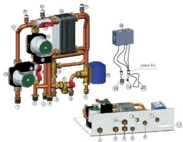
natural_image
Pure electrical circuit lines without any symbolsKIT N3 BIS
code 627860
EXEMPLE DE SYSTÈME HYDRAULIQUE POUR THERMOPOÈLES AVEC PRODUCTION D'EAU CHAUDE SANITAIRE EN ACCUMULATION + CHAUDIÈRE MURALE
AVEC UTILISATION D'IDROKIT
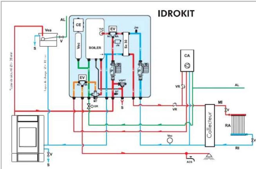
flowchart
graph TD
    A["Top view de securé d'g - 26 mm"] --> B["Vea"]
    B --> C["S"]
    C --> D["Boiler"]
    D --> E["TC"]
    D --> F["EV"]
    D --> G["Sc 30"]
    D --> H["VSPT"]
    D --> I["MT"]
    D --> J["OR"]
    D --> K["ST"]
    D --> L["JS"]
    D --> M["VA"]
    D --> N["VA"]
    D --> O["VA"]
    D --> P["VA"]
    D --> Q["VA"]
    D --> R["VA"]
    D --> S["VA"]
    D --> T["VA"]
    D --> U["VA"]
    D --> V["VA"]
    D --> W["VA"]
    D --> X["VA"]
    D --> Y["VA"]
    D --> Z["VA"]
    D --> AA["VA"]
    D --> AB["VA"]
    D --> AC["VA"]
    D --> AD["VA"]
    D --> AE["VA"]
    D --> AF["VA"]
    D --> AG["VA"]
    D --> AH["VA"]
    D --> AI["VA"]
    D --> AJ["VA"]
    D --> AK["VA"]
    D --> AL["VA"]
    D --> AM["VA"]
    D --> AN["VA"]
    D --> AO["VA"]
    D --> AP["VA"]
    D --> AQ["VA"]
    D --> AR["VA"]
    D --> AS["VA"]
    D --> AT["VA"]
    D --> AU["VA"]
    D --> AV["VA"]
    D --> AW["VA"]
    D --> AX["VA"]
    D --> AY["VA"]
    D --> AZ["VA"]
    D --> BA["VA"]
    D --> BB["VA"]
    D --> BC["VA"]
    D --> BD["VA"]
    D --> BE["VA"]
    D --> BF["VA"]
    D --> BG["VA"]
    D --> BH["VA"]
    D --> BI["VA"]
    D --> BJ["VA"]
    D --> BK["VA"]
    D --> BL["VA"]
    D --> BM["VA"]
    D --> BN["VA"]
    D --> BO["VA"]
    D --> BP["VA"]
    D --> BQ["VA"]
    D --> BR["VA"]
    D --> BS["VA"]
    D --> BT["VA"]
    D --> BU["VA"]
    D --> BV["VA"]
    D --> BW["VA"]
    D --> BX["VA"]
    D --> BY["VA"]
    D --> BZ["VA"]
C: Charge/ Compensation
C: Charge/Compensation
natural_image
Industrial equipment setup with a rectangular chamber and piping (no visible text or symbols)KIT 5
code 280590
EXEMPLE DE SYSTÈME HYDRAULIQUE POUR THERMOPOÈLES AVEC PRODUCTION D'EAU CHAUDE SANITAIRE
AVEC UTILISATION DU
KIT 6
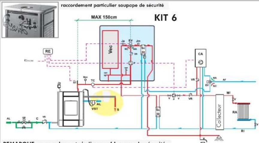
C: Charge/Compensation
E Evacuation soupape suppression
natural_image
Industrial equipment setup with pressure vessel, pipes, and control panel (no visible text or symbols)KIT 6
code 280600
SS voyant surchauffe
- voyant surchauffe (SS)
- voyant pompe (SP)
Fonctionnement
natural_image
Exterior view of a modern outdoor stove with visible flames and ventilation grilles (no text or symbols)KLIMA BASE

natural_image
Modern portable stove with visible flame inside, mounted on a metal frame (no text or symbols)WARM BASE
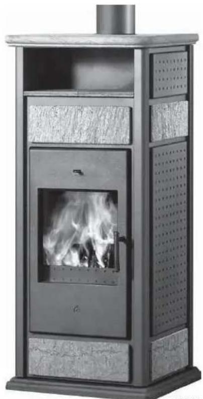
natural_image
Exterior view of a modern outdoor stove with visible flames and ventilation grilles (no text or symbols)natural_image
Exterior view of a modern metal portable stove with visible flames and ventilation grilles (no text or symbols)WARM con CALIENTAPLATOS
natural_image
Close-up of a hand using a tool to adjust or install a component on a metal panel (no visible text or symbols)BY-PASS AUTOMÁTICO DE HUMOS
natural_image
Close-up of a mechanical joint or bracket with a metallic component and a curved arrow indicating direction (no text or symbols visible)natural_image
Exterior view of a laboratory instrument cabinet with tubing and ventilation ducts (no visible text or symbols)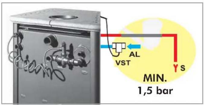
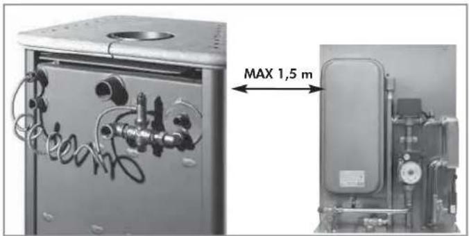
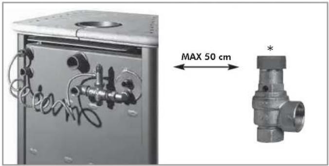
natural_image
Exterior view of a gray rectangular device with a small label and a large question mark symbol on the right (no text or symbols on device)1 año
natural_image
Technical line drawing of a mechanical device with a vertical shaft and base, showing internal components (no text or symbols)2
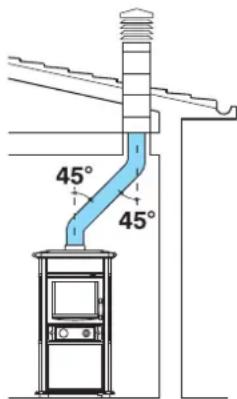
3
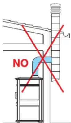
4
- Canale da fumo
natural_image
Pure diagram of two vertical panels with dot patterns and a small rectangular inset, no text or symbols present.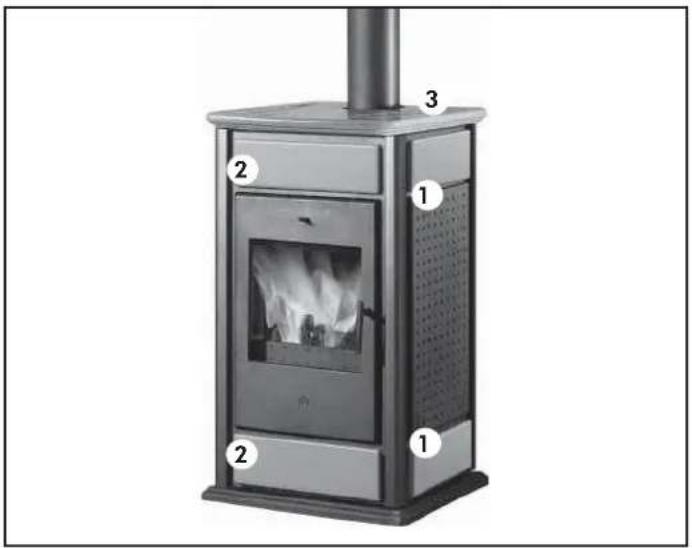
SET CERÁMICAS
WARM / KLIMA base
Para WARM / KLIMA BASE:
- 4 elementos laterales (1)
- 2 elementos anteriores (2)
- 1 tapa (3)
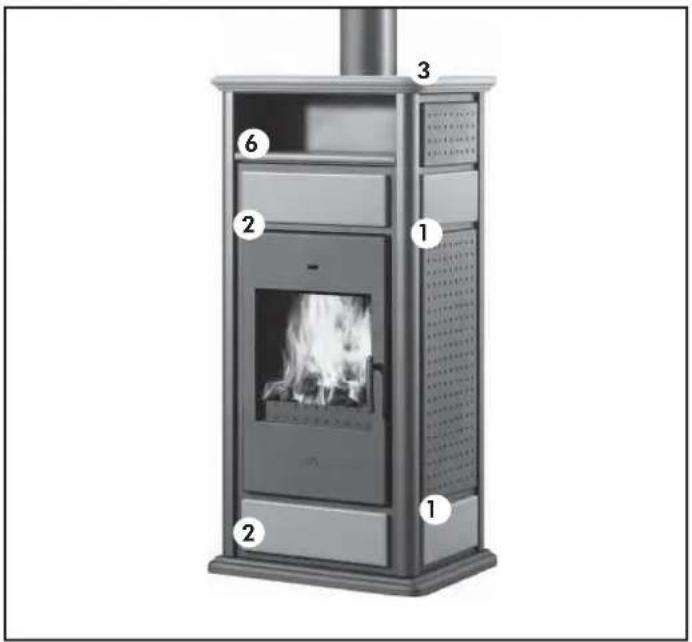
SET CERÁMICAS
WARM / KLIMA con calientaplatos
natural_image
Industrial piping system mounted on a metal frame, no visible text or symbolsKIT 1
cod. 261880
natural_image
Industrial piping system mounted on a metal frame, no visible text or symbolsKIT 2
cod. 261890
natural_image
Industrial piping and valve assembly with no visible text or symbolsKIT 3
cod. 261900
natural_image
Pure technical diagram of a heat exchanger or cooling system with pipes and valves (no text or labels)KIT N3
cod. 627690
INT: interruptor general
TCN: Termostato de contacto
natural_image
Pure mechanical piping diagram with no text, numbers, or symbolsKIT N3 BIS
cod. 627860
ESEMPIO DI IMPIANTO IDRAULICO PER TERMOSTUFA CON PRODUZIONE DI ACQUA CALDA SANITARIA IN ACCUMULO + CALDAIA MURALE
CON UTILIZZO DI
IDROKIT
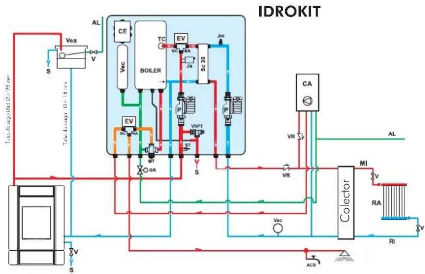
flowchart
graph TD
    A["Top downgate 20-76 mm"] --> B["Vea"]
    B --> C["S"]
    C --> D["Valve"]
    D --> E["VEa"]
    E --> F["V"]
    F --> G["Boiler"]
    G --> H["TC"]
    H --> I["NC"]
    H --> J["RA"]
    H --> K["Sc 30"]
    K --> L["Jm"]
    L --> M["P"]
    M --> N["Cap"]
    N --> O["Colector"]
    O --> P["MI"]
    P --> Q["RA"]
    Q --> R["RI"]
    R --> S["ACS"]
    S --> T["Valve"]
    T --> U["S"]
    U --> V["Valve"]
    V --> W["Boiler"]
    W --> X["EV"]
    X --> Y["MT"]
    Y --> Z["GR"]
    Z --> AA["PT"]
    AA --> AB["VSPT"]
    AB --> AC["SC 30"]
    AC --> AD["Jm"]
    AD --> AE["P"]
    AE --> AF["Cap"]
    AF --> AG["Colector"]
    AG --> AH["MI"]
    AH --> AI["RA"]
    AI --> AJ["RI"]
    AJ --> AK["ACS"]
ACS: Agua caliente Sanitario
AF: Agua fría
natural_image
Industrial pressure pump unit with control panel and piping (no visible text or symbols)KIT 5
cód. 280590
natural_image
Industrial equipment setup with pipes, valves, and a control panel (no visible text or symbols)KIT 6
cód. 280600
- selector MAN-OFF-AUTO(S)
- escala temperatura(ST)
- alarma acústica (AA)
KLIMA - WARM: UNI EN 13240:2006
KLIMA/CS - WARM/CS: UNI EN 13240:2006
natural_image
Exterior view of a modern portable stove with visible flames and ventilation grilles (no text or symbols on the stove itself)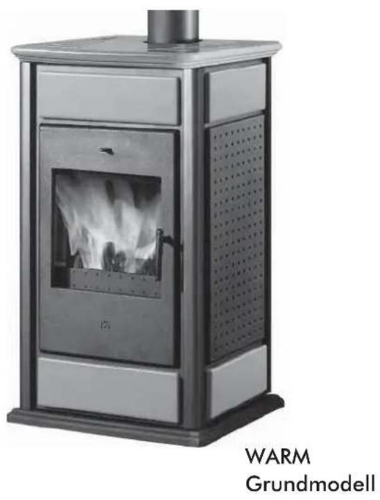
natural_image
Exterior view of a WARM Grundmodell electric stove with visible flame inside (no text or symbols on the device itself)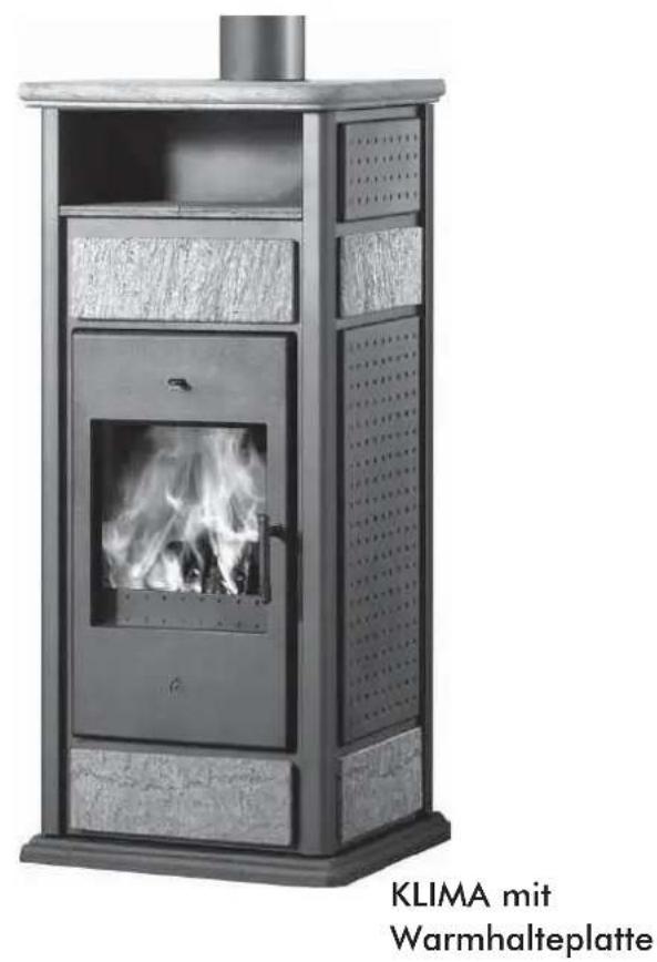
natural_image
Exterior view of a modern outdoor stove with visible flames and ventilation grilles (no text or symbols on the main structure)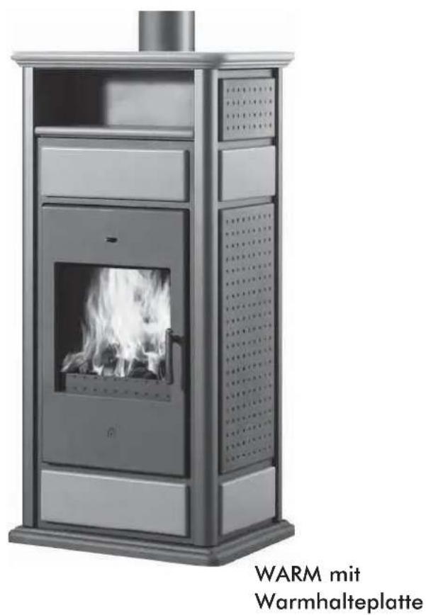
natural_image
Exterior view of a WARM warmhalteplatte industrial stove with visible flame inside (no text or symbols on the device itself)natural_image
Close-up of a hand using a screwdriver to adjust a component on a metal panel (no visible text or symbols)AUTOMATISCHE ABGASKLAPPE
natural_image
Close-up of a mechanical joint or bracket with a curved arrow indicating direction (no visible text or symbols)natural_image
Interior view of a laboratory instrument cabinet with tubing and ventilation ducts (no visible text or labels)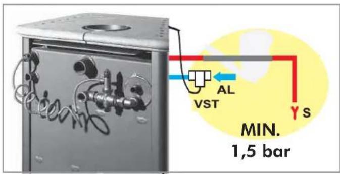
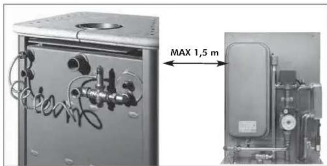
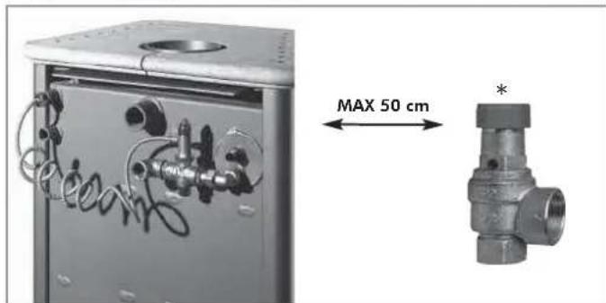
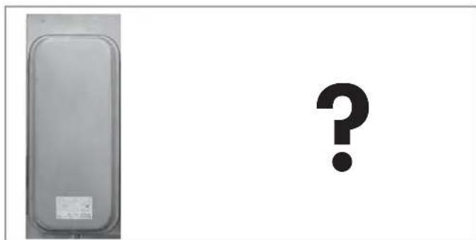
natural_image
Exterior view of a rectangular device with a small mark on the left, next to a large question mark symbol (no text or labels present)1 Jahr
natural_image
Technical line drawing of a vertical industrial structure with a blue component and support beams (no text or symbols)2
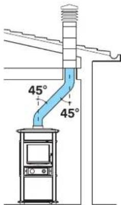
3
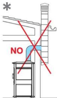
4
- Rauchkanal
natural_image
Pure electrical circuit lines without any symbols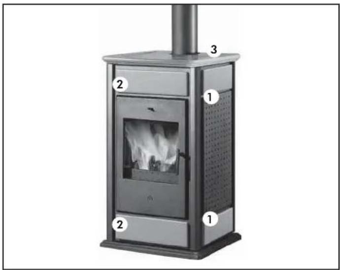
natural_image
Exterior view of a modern portable stove with labeled components (no text or symbols on the stove itself)KERAMIKKACHEL SET WARM / KLIMA Grundmodell
natural_image
Industrial piping system mounted on a metal frame, no visible text or symbolsnatural_image
Industrial piping system with valves and a control panel, mounted on a metal frame (no visible text or symbols)natural_image
Industrial piping and valve assembly with no visible text or symbolsflowchart
graph TD
    A["Stromnetz ∅28 cm"] --> B["VE"]
    B --> C["S"]
    C --> D["TCN"]
    D --> E["ST"]
    E --> F["Re"]
    F --> G["CA"]
    G --> H["TA"]
    H --> I["WR"]
    I --> J["Sammelleitung"]
    J --> K["RA"]
    K --> L["ACS"]
    L --> M["ACS"]
    M --> N["VR"]
    N --> O["WR"]
    O --> P["WR"]
    P --> Q["WR"]
    Q --> R["WR"]
    R --> S["WR"]
    S --> T["WR"]
    T --> U["WR"]
    U --> V["WR"]
    V --> W["WR"]
    W --> X["WR"]
    X --> Y["WR"]
    Y --> Z["WR"]
    Z --> AA["WR"]
    AA --> AB["WR"]
    AB --> AC["WR"]
    AC --> AD["WR"]
    AD --> AE["WR"]
    AE --> AF["WR"]
    AF --> AG["WR"]
    AG --> AH["WR"]
    AH --> AI["WR"]
    AI --> AJ["WR"]
    AJ --> AK["WR"]
    AK --> AL["WR"]
    AL --> AM["WR"]
    AM --> AN["WR"]
    AN --> AO["WR"]
    AO --> AP["WR"]
    AP --> AQ["WR"]
    AQ --> AR["WR"]
    AR --> AS["WR"]
    AS --> AT["WR"]
    AT --> AU["WR"]
    AU --> AV["WR"]
    AV --> AW["WR"]
    AW --> AX["WR"]
CA: Wandheizkessel
PR: Umwälzpumpe
natural_image
Technical diagram of a heat exchanger system with pipes, valves, and control panel (no text or labels)natural_image
Pure mechanical piping diagram with no text, numbers, or symbolsP: Pumpe (Zirkulator)
RA: Heizkörper
RI: Rücklauf Anlage
S: Abfluss
natural_image
Industrial piping and valve assembly (no visible text or symbols)KIT 5
Bestennlr. 280590
natural_image
Industrial piping and valve assembly (no visible text or symbols)KIT 6
Bestennlr. 280600
natural_image
Exterior view of a modern outdoor stove with visible flames and ventilation grilles (no text or symbols on the stove itself)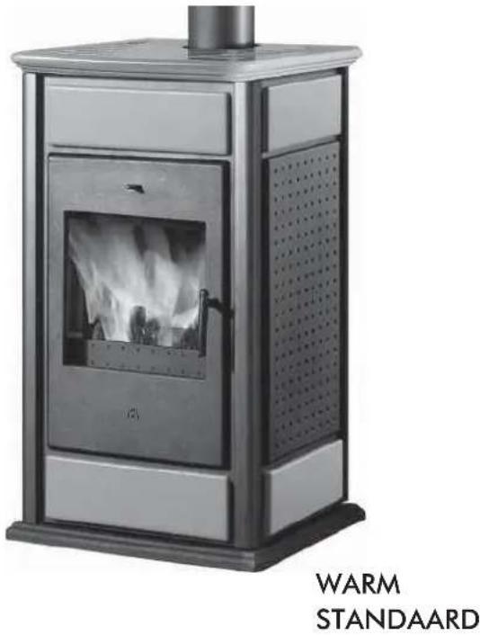
natural_image
Exterior view of a portable stove with visible flames and ventilation grilles (no text or symbols on the main body)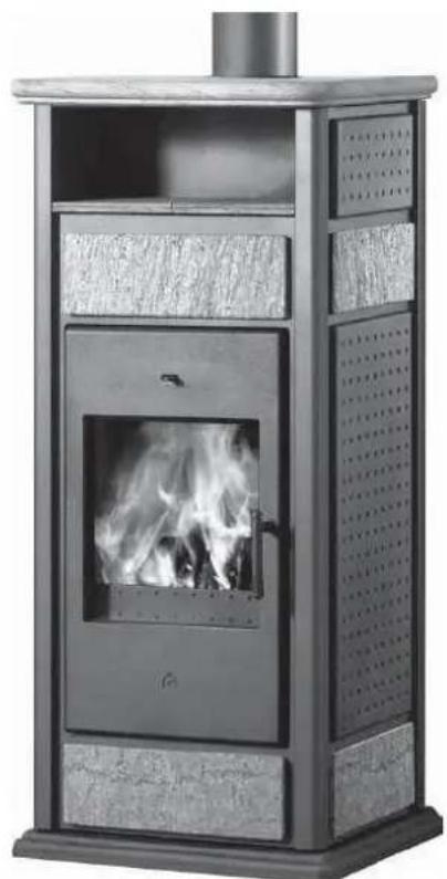
natural_image
Exterior view of a modern outdoor stove with visible flames and ventilation grilles (no text or symbols)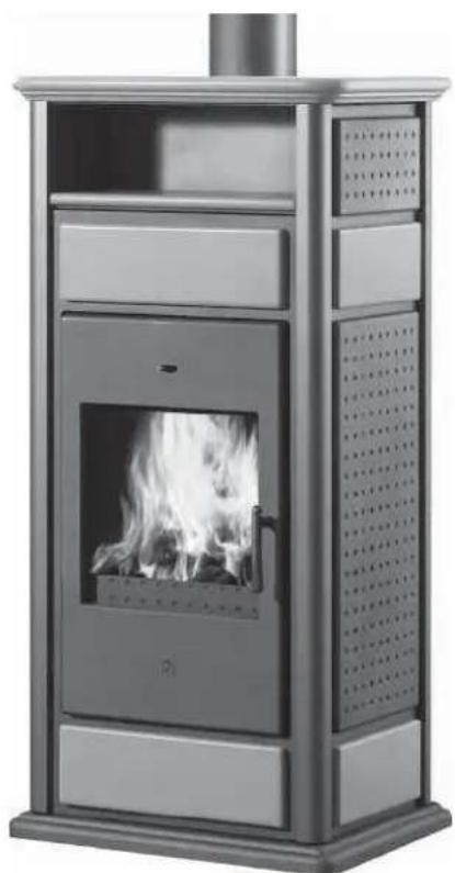
natural_image
Modern metal portable stove with visible flame inside, no text or symbols presentnatural_image
Close-up of a hand using a tool to adjust or install a component on a metal panel (no visible text or symbols)AUTOMATISCHE BY-PASS ROOK
natural_image
Close-up of a mechanical joint or bracket with a metallic rod and mounting base, showing a curved arrow indicating direction (no text or symbols visible)AUTOMATISCHE AFSLUITING DEURTJE
natural_image
Interior view of a laboratory instrument cabinet with tubing and ventilation ducts (no visible text or labels)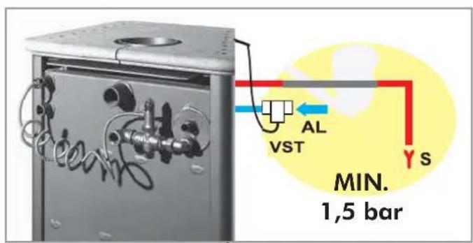

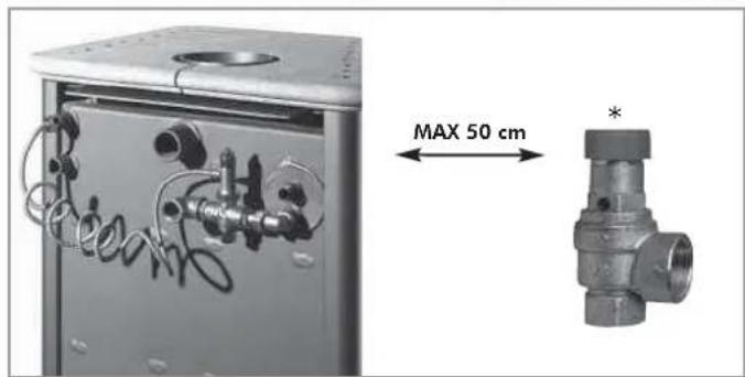
natural_image
Exterior view of a gray rectangular device with a small mark on the left, next to a large black question mark symbol (no text or labels present)1 Jaar
natural_image
Technical line drawing of a vertical industrial structure with a blue component mounted on a base (no text or symbols)2
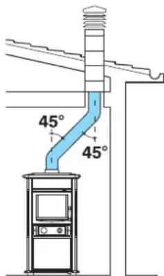
3
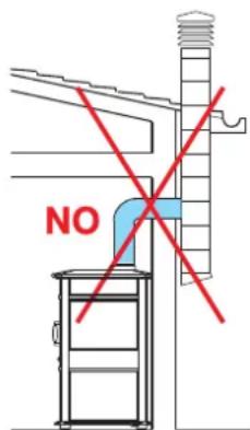
4
- Rookkanaal
natural_image
Pure electrical circuit lines without any symbols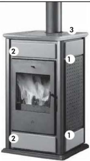
natural_image
Exterior view of a modern portable stove with visible flames and ventilation grilles (no text or symbols)SET KERAMIEKEN ELEMENTEN WARM / KLIMA standaard
1 Geelkoperen collector 1' M-V
2 Kogelklep van 1
F Warm tapwater 1/2"
natural_image
Industrial piping system with valves and connectors inside a metal enclosure (no visible text or symbols)PAKKET 1
cod. 261880
VOORBEELD VAN EEN HYDRAULISCHE INSTALLATIE VOOR INBOUWHAARD ZONDER PRODUCTIE VAN WARM TAPWATER+WANDKETEL
MET GEBRUIK VAN
PAKKET 2
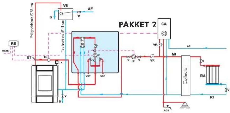
flowchart
graph TD
    RE["RE"] --> ST["ST"]
    RE --> TA["TA"]
    TA --> S["S"]
    S --> VE["VE"]
    VE --> V["V"]
    V --> AF["AF"]
    VA["VA"] --> SC["Sc 30"]
    VA --> P["P"]
    VA --> VST["VST"]
    VA --> VSP["VSP"]
    VST --> V["P"]
    VSP --> VV["V"]
    VST --> VR["V"]
    VSP --> VVR["V"]
    VR --> CA["CA"]
    CA --> AV["AV"]
    AV --> MI["MI"]
    MI --> Collector["Collector"]
    Collector --> RA["RA"]
    Collector --> RI["RI"]
    RI --> AC["ACS"]
    AC --> TA
    style RA fill:#f9f,stroke:#333
    style RI fill:#f9f,stroke:#333
    style VI fill:#ccf,stroke:#333
    style VT fill:#ccf,stroke:#333
    style U fill:#cfc,stroke:#333
    style V fill:#fcc,stroke:#333
    style W fill:#ffc,stroke:#333
    style TA fill:#ffc,stroke:#333
    style VT fill:#ffc,stroke:#333
    style V fill:#ffc,stroke:#333
    style VST fill:#cfc,stroke:#333
    style VSP fill:#cfc,stroke:#333
    style VBR fill:#fcc,stroke:#333
    style VVR fill:#fcc,stroke:#333
    style AV fill:#fff,stroke:#333
    style VI fill:#fff,stroke:#333
    style VT fill:#fff,stroke:#333
    style VWR fill:#fff,stroke:#333
    style VBR fill:#fff,stroke:#333
    style VVR fill:#fff,stroke:#333
    style VBR fill:#fff,stroke:#333
    style VBR fill:#fff,stroke:#333
    style VBR fill:#fff,stroke:#333
    style VBR fill:#fff,stroke:#333
    style VBR fill:#fff,stroke:#333
    style VBR fill:#fff,stroke:#333
    style VBR fill:#fff,stroke:#333
    style VBR fill#ff,stroke:#333
AF: Koud water
CA: Wandketel
P: Pomp (circulator)
RA: Radiators
E Koud tapwater 1/2"
F Warm tapwater 1/2"
natural_image
Industrial piping system with valves and a control unit, mounted on a metal frame (no visible text or symbols)PAKKET 2 cod. 261890
VOORBEELD VAN EEN HYDRAULISCHE INSTALLATIE VOOR INBOUWHAARD MET PRODUCTIE VAN WARM TAPWATER+WANDKETEL MET GEBRUIK VAN PAKKEI 3
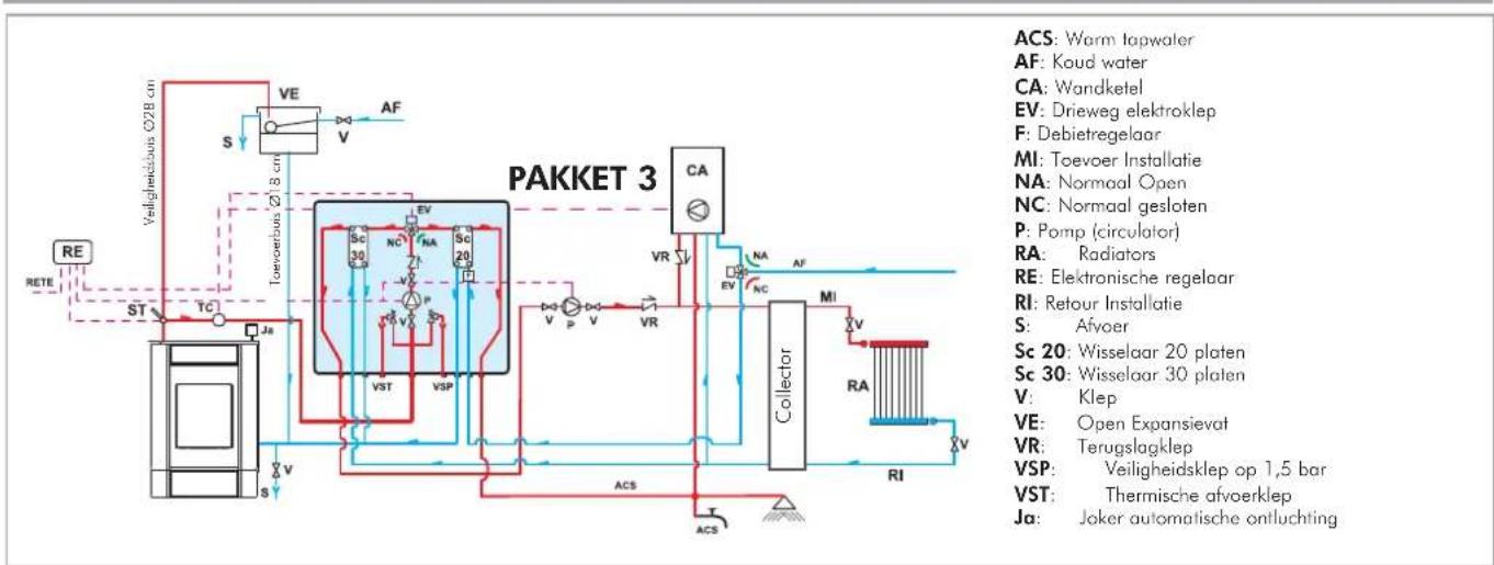
ACS: Warm lapwater
AF: Koud water
CA: Wandketel
EV: Drieweg elektroklep
F: Debietregelaar
MI: Toevoer Installatie
NA: Normaal Open
NC: Normaal gesloten
P: Pomp (circulator)
RA: Radiators
RE: Elektronische regelaar
RI: Retour Installatie
S: Afvoer
Sc 20: Wisselaar 20 platen
Sc 30: Wisselaar 30 platen
V: Klep
VE: Open Expansievat
VR: Terugslagklep
VSP: Veiligheidsklep op 1,5 bar
VST: Thermische afvoerklep
Ja: Joker automatische ontluchting
natural_image
Industrial piping and valve assembly with cooling fans and valves (no visible text or labels)PAKKET 3 cod. 261900
VOORBEELD VAN EEN HYDRAULISCHE INSTALLATIE VOOR INBOUWHAARD MET PRODUCTIE VAN WARM TAPWATER+WANDKETEL MET GEBRUIK VAN PAKKET N3
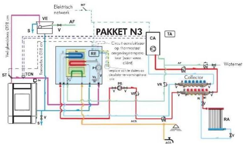
flowchart
graph TD
    A["Veil gredschuss ∅28 cm"] --> B["TCN"]
    B --> C["ST"]
    C --> D["Toeschuss ∅28 cm"]
    D --> E["VE"]
    E --> F["S"]
    F --> G["RE"]
    G --> H["Pf"]
    H --> I["Vs"]
    I --> J["VA"]
    J --> K["CA"]
    K --> L["TA"]
    L --> M["Collector"]
    M --> N["RA"]
    N --> O["V"]
    O --> P["ACS"]
    P --> Q["VR"]
    Q --> R["WR"]
    R --> S["Watermelting"]
    T["Circuit aansluitbaar op thermostaat omgevingstempero laur (naar wens client)"]
    U["verplicen on le dlaties op circulator verwarmingstals ole"] --> V["PR"]
    V --> W["V"]
    W --> X["VR"]
    X --> Y["WR"]
    Y --> Z["WR"]
    Z --> AA["WR"]
    AA --> AB["WR"]
    AB --> AC["WR"]
    AC --> AD["WR"]
    AD --> AE["WR"]
    AE --> AF["WR"]
    AF --> AG["WR"]
    AG --> AH["WR"]
    AH --> AI["WR"]
    AI --> AJ["WR"]
    AJ --> AK["WR"]
    AK --> AL["WR"]
    AL --> AM["WR"]
    AM --> AN["WR"]
    AN --> AO["WR"]
    AO --> AP["WR"]
    AP --> AQ["WR"]
    AQ --> AR["WR"]
    AR --> AS["WR"]
    AS --> AT["WR"]
    AT --> AU["WR"]
    AU --> AV["WR"]
    AV --> AW["WR"]
    AW --> AX["WR"]
    AX --> AY["WR"]
natural_image
Pure mechanical piping diagram without any text, numbers, or symbolsPAKKET N3 cod. 627690
VOORBEELD VAN EEN HYDRAULISCHE INSTALLATIE VOOR INBOUWHAARD MET PRODUCTIE VAN WARM TAPWATER+WANDKETEL
MET GEBRUIK VAN
PAKKET N3 BIS
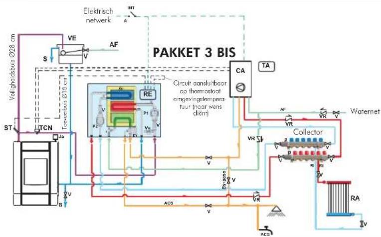
flowchart
graph TD
    A["Valg hoidbus Ø28 cm"] --> B["TCN"]
    B --> C["St"]
    C --> D["VE"]
    D --> E["S"]
    E --> F["Re"]
    F --> G["P1"]
    G --> H["V"]
    H --> I["P2"]
    I --> J["V"]
    J --> K["P3"]
    K --> L["V"]
    L --> M["P4"]
    M --> N["V"]
    N --> O["P5"]
    O --> P["V"]
    P --> Q["P6"]
    Q --> R["V"]
    R --> S["P7"]
    S --> T["V"]
    T --> U["P8"]
    U --> V["V"]
    V --> W["P9"]
    W --> X["V"]
    X --> Y["P10"]
    Y --> Z["V"]
    Z --> AA["P11"]
    AA --> AB["V"]
    AB --> AC["P12"]
    AC --> AD["V"]
    AD --> AE["P13"]
    AE --> AF["V"]
    AF --> AG["P14"]
    AG --> AH["V"]
    AH --> AI["P15"]
    AI --> AJ["V"]
    AJ --> AK["P16"]
    AK --> AL["V"]
    AL --> AM["P17"]
    AM --> AN["V"]
    AN --> AO["P18"]
    AO --> AP["V"]
    AP --> AQ["P19"]
    AQ --> AR["V"]
    AR --> AS["P20"]
    AS --> AT["V"]
    AT --> AU["P21"]
    AU --> AV["V"]
    AV --> AW["P22"]
    AW --> AX["V"]
    AX --> AY["P23"]
    AY --> AZ["V"]
    AZ --> BA["P24"]
    BA --> BB["V"]
    BB --> BC["P25"]
    BC --> BD["V"]
    BD --> BE["P26"]
    BE --> BF["V"]
    BF --> BG["P27"]
    BG --> BH["V"]
    BH --> BI["P28"]
    BI --> BJ["V"]
    BJ --> BK["P29"]
    BK --> BL["V"]
    BL --> BM["P30"]
    BM --> BN["V"]
    BN --> BO["P31"]
    BO --> BP["V"]
    BP --> BQ["P32"]
    BQ --> BR["V"]
    BR --> BS["P33"]
    BS --> BT["V"]
    BT --> BU["P34"]
    BU --> BV["V"]
    BV --> BW["P35"]
    BW --> BX["V"]
    BX --> BY["P36"]
    BY --> BZ["V"]
    BZ --> CA["CA TA"]

    subgraph "PAKKET 3 BIS"
        direction TB
        direction LR
        direction SB
        direction RV
        direction VL
        direction DV
        direction DV
        direction DV
        direction DV
        direction DV
        direction DV
        direction DV
        direction DV
        direction DV
        direction DV
        direction DV
        direction DV
        direction DV
        direction DV
        direction DV
        direction DV
        direction DV
        direction DV
        direction DV
        direction DV
        direction DV
        direction DV
        direction DV
        direction DV
        direction DV
        direction GV
        direction GV
        direction GV
        direction GV
        direction GV
        direction GV
        direction GV
        direction GV
        direction GV
        direction GV
        direction GV
        direction GV
        direction GV
        direction GV
        direction GV
        direction GV
        direction GV
        direction GV
        direction GV
        direction GV
        direction GV
        direction GV
        direction GV
        direction GV
        direction GV
        direction SV
        direction SV
        direction SV
        direction SV
        direction SV
        direction SV
        direction SV
        direction SV
        direction SV
        direction SV
        direction SV
        direction SV
        direction SV
        direction SV
        direction SV
        direction SV
        direction SV
        direction SV
        direction SV
        direction SV
        direction SV
        direction SV
        direction SV
        direction SV
        direction SV
        direction GV
        direction GV
        direction GV
        direction GV
        direction GV
        direction GV
        direction GV
        direction GV
        direction GV
        direction GV
        direction GV
        direction GV
        direction GV
        direction GV
        direction GV
        direction GV
        direction GV
        direction GV
        direction GV
        direction GV
        direction GV
        direction GV
        direction GV
        direction GV
        direction VGRAVRAVRAVRAVRAVRAVRAVRAVRAVRAVRAVRAVRAVRAVRAVRAVRAVRAVRAVRAVRAVRAVRAVRAVRAVRAVRAVRAVRAVRAVRAVRAVRAVRAVRAVRAVRAVRAVRAVRAVRAVRAVRAVRAVRAVRAVRAVRAVRAVRAVRAFVAFAFAFAFAFAFAFAFAFAFAFAFAFAFAFAFAFAFAFAFAFAFAFAFAFAFAFAFAFAFAFAFAFAFAFAFAFAFAFAFAFAFAFAFAFAFAFAFAFAFAFAFAFAFAFAFAFAFAFAFAFAFAFAFAFAFAFAFAFAFAFAFAFAFAFAFAFAFAFVAFFAACCVAFFAACCVAFFAACCVAFFAACCVAFFAACCVAFFAACCVAFFAACCVAFFAACCVAFFAACCVAFFAACCVAFFAACCVAFFAACCVAFFAACCVAFFAACCVAFFAACCVAFFAACCVAFFAACCVAFFAACCVAFFAACCVAFFAACCVAFFAACCVAFFAACCVAFFAACCVAFFAACCVAFFAACCVAFFAATTVAFFAATTVAFFAATTVAFFAATTVAFFAATTVAFFAATTVAFFAATTVAFFAATTVAFFAATTVAFFAATTVAFFAATTVAFFAATTVAFFAATTVAFFAATTVAFFAATTVAFFAATTVAFFAATTVAFFAATTVAFFAATTVAFFAATTVAFFAATTVAFFAATTVAFFAATTVAFFAATTVAFFAATTVAFFAATTAFFAATTAFFAATTAFFAATTAFFAATTAFFAATTAFFAATTAFFAATTAFFAATTAFFAATTAFFAATTAFFAATTAFFAATTAFFAATTAFFAATTAFFAATTAFFAATTAFFAATTAFFAATTAFFAATTAFFAATTAFFAATTAFFAATTAFFAATTAFFAATTAFFAATTTAGCCTCACTCACTCACTCACTCACTCACTCACTCACTCACTCACTCACTCACTCACTCACTCACTCACTCACTCACTCACTCACTCACTCACTCACTCACTCACTCACTCACTCACTCACTCACTCACTCACTCACTCACTCACTCACTCACTCACTCACTCACTCACTCACTCACTCACTCACTCACTCACTCACTCACTCACTCCACTCACTCACTCACTCACTCACTCACTCACTCACTCACTCACTCACTCACTCACTCACTCACTCACTCACTCACTCACTCACTCACTCACTCACTCACTCACTCACTCACTCACTCACTCACTCACTCACTCACTCACTCACTCACTCACTCACTCACTCACTCACTCACTCACTCACTCACTCACTCACTCACTCACTCAACTCACTCACTCACTCACTCACTCACTCACTCACTCACTCACTCACTCACTCACTCACTCACTCACTCACTCACTCACTCACTCACTCACTCACTCACTCACTCACTCACTCACTCACTCACTCACTCACTCACTCACTCACTCACTCACTCACTCACTCACTCACTCACTCATCCACTCATCCACTCATCCACTCATCCACTCATCCACTCATCCACTCATCCACTCATCCACTCATCCACTCATCCACTCATCCACTCATCCACTCATCCACTCATCCACTCATCCACTCATCCACTCATCCACTCATCCACTCATCCACTCATCCACTCATCCACTCATCCACTCATCCACTCATCCACTCATCCACTCATCCACTCATCCACTCATCCACTCATCCACTCATCCACTCATCCACTCATCCACTCATCCACTCATCCACTATCCACTCATCCACTCATCCACTCATCCACTCATCCACTCATCCACTCATCCACTCATCCACTCATCCACTCATCCACTCATCCACTCATCCACTCATCCACTCATCCACTCATCCACTCATCCACTCATCCACTCATCCACTCATCCACTCATCCACTCATCCACTCATCCACTCATCCACTCATCCACTCATCCACTCATCCACTCATCCACTCATCCACTCATCCACTCATCCACTCATCCACTCATCCACTCATCCACTCATCCCACATCCCACATCCCACATCCCACATCCCACATCCCACATCCCACATCCCACATCCCACATCCCACATCCCACATCCCACATCCCACATCCCACATCCCACATCCCACATCCCACATCCCACATCCCACATCCCACATCCCACATCCCACATCCCACATCCCACATCCCACATCCCACATCCCACATCCCACATCCCACATCCCACATCCCACATCCCACATCCCACATCCCACATCCCCACATCCCACATCCCACATCCCACATCCCACATCCCACATCCCACATCCCACATCCCACATCCCACATCCCACATCCCACATCCCACATCCCACATCCCACATCCCACATCCCACATCCCACATCCCACATCCCACATCCCACATCCCACATCCCACATCCCACATCCCACATCCCACATCCCACATCCCACATCCCACATCCCACATCCCACATCCCACATCCCACATCCCAGTAAAGTAAAGTAAAGTAAAGTAAAGTAAAGTAAAGTAAAGTAAAGTAAAGTAAAGTAAAGTAAAGTAAAGTAAAGTAAAGTAAAGTAAAGTAAAGTAAAGTAAAGTAAAGTAAAGTAAAGTAAAGTAAAGTAAAGTAAAGTAAAGTAAAGTAAAGTAAAGTAAAGTAAUGGCGCGCGCGCGCGCGCGCGCGCGCGCGCGCGCGCGCGCGCGCGCGCGCGCGCGCGCGCGCGCGCGCGCGCGCGCGCGCGCGCGCGCGCGCGCGCGCGCGCGCGCGCGCGCGCGCGCGCGCGCGCGCGCGCGCGCGCGCGCGCGCGCGCGCGCGCGCGCGCGCGCGCGCGCGCGCGCGCGCGCGCGCGCGCGCGCGCGCGCGGCGGCGGCGGCGGCGGCGGCGGCGGCGGCGGCGGCGGCGGCGGCGGCGGCGGCGGCGGCGGCGGCGGCGGCGGCGGCGGCGGCGGCGGCGGCGGCGGCGGCGGCGGCGGCGGCGGCGGCGGCGGCGGCGGTCGAATAAGGTGGGGGGGGGGGGGGGGGGGGGGGGGGGGGGGGGGGGGGGGGGGGGGGGGGGGGGGGGGGGGGGGGGGGGGGGGGGGGGGGGGGGGGGGGGGGGGGGGGGGGGGGGGGGGGGGGGGGGGGGGGGGGGGGGGGGGGGGGGGGGGGGGGGGGGGGGGGGGGGGGGGGGGGGGGGGGGGGggGAATAAGGTGGGGGGGGGGGGGGGGGGGGGGGGGGGGGGGGGGGGGGGGGGGGGGGGGGGGGGGGGGGGGGGGGGGGGGGGGGggGAATAAGGTGGGWWGGAATAAGGTGGAATAAGGTGGAATAAGGTGGAATAAGGTGGAATAAGGTGGAATAAGGTGGAATAAGGTGGAATAAGGTGGAATAAGGTGGAATAAGGTGGAATAAGGTGGAATAAGGTGGAATAAGGTGGAATAAGGTGGAATAAGGTGGAATAAGGTGGAATAAGGTGGAATAAGGTGGAATAAGGTGGAATAAGGTGGAATAAGOTGAATAAGGTGAATAAGGTGAATAAGGTGAATAAGGTGAATAAGGTGAATAAGGTGAATAAGGTGAATAAGGTGAATAAGGTGAATAAGGTGAATAAGGTGAATAAGGTGAATAAGGTGAATAAGGTGAATAAGGTGAATAAGGTGAATAAGGTGAATAAGGTGAATAAGGTGAATAAGGTGAATAAGGTGAATAAGGTGAATAAGGTGAATAAGGTGAATAAGGTGAATAAGOTGAATAAGGTGAATAAGGTGAATAAGGTGAATAAGGTGAATAAGGTGAATAAGGTGAATAAGGTGAATAAGGTGAATAAGGTGAATAAGGTGAATAAGGTGAATAAGGTGAATAAGGTGAATAAGGTGAATAAGGTGAATAAGGTGAATAAGGTGAATAAGGTGAATAAGGTGAATAAGGTGAATAAGGTGAATAAGGTGAATAAGGTGAATAAGOTGAATAAGOTGAATAAGOTGAATAAGOTGAATAAGOTGAATAAGOTGAATAAGOTGAATAAGOTGAATAAGOTGAATAAGOTGAATAAGOTGAATAAGOTGAATAAGOTGAATAAGOTGAATAAGOTGAATAAGOTGAATAAGOTGAATAAGOTGAATAAGOTGAATAAGOTGAATAAGOTGAATAAGOTGAATAAGOTGAATAAGOTGAATAAGOTGAATAAGOVTGAAVTGAAVTGAAVTGAAVTGAAVTGAAVTGAAVTGAAVTGAAVTGAAVTGAAVTGAAVTGAAVTGAAVTGAAVTGAAVTGAAVTGAAVTGAAVTGAAVTGAAVTGAAVTGAAVTGAAVTGAAVTGAAVTGAAVTGAAVTGAAVTGAAVTGAAVTGAAVTGAAVTGAAWTTCGCACAUCUCUCUCUCUCUCUCUCUCUCUCUCUCUCUCUCUCUCUCUCUCUCUCUCUCUCUCUCUCUCUCUCUCUCUCUCUCUCUCUCUCUCUCUCUCUCUCUCUCUCUCUCUCUCUCUCUCUCUCUCUCUCUCUCUCUCUCUCUCUCUCUCUCUCUCUCUCUCUCUCUCUCUCUCUCUCUCUCUCUCUCUCUCUCUCUCUCUCUCUANTICVCACAUCUANTICVCACAUCUANTICVCACAUCUANTICVCACAUCUANTICVCACAUCUANTICVCACAUCUANTICVCACAUCUANTICVCACAUCUANTICVCACAUCUANTICVCACAUCUANTICVCACAUCUANTICVCACAUCUANTICVCACAUCUANTICVCACAUCUANTICVCACAUCUANTICVCACAUCUANTICVCACAUCUANTIGCACAUCUANTIGCACAUCUANTIGCACAUCUANTIGCACAUCUANTIGCACAUCUANTIGCACAUCUANTIGCACAUCUANTIGCACAUCUANTIGCACAUCUANTIGCACAUCUANTIGCACAUCUANTIGCACAUCUANTIGCACAUCUANTIGCACAUCUANTIGCACAUCUANTIGCACAUCUANTIGCACAUCUINTIGCACA UNTIGCACA UNTIGCACA UNTIGCACA UNTIGCACA UNTIGCACA UNTIGCACA UNTIGCACA UNTIGCACA UNTIGCACA UNTIGCACA UNTIGCACA UNTIGCACA UNTIGCACA UNTIGCACA UNTIGCACA UNTIGCACA UNTIGCACA UNTIGCACA UNTIGCACA UNTIGCACA UMTTCGCACA UMTTCGCACA UMTTCGCACA UMTTCGCACA UMTTCGCACA UMTTCGCACA UMTTCGCACA UMTTCGCACA UMTTCGCACA UMTTCGCACA UMTTCGCACA UMTTCGCACA UMTTCGCACA UMTTCGCACA UMTTCGCACA UMTTCGCACA UMTTCGCACA UMTTCGCACA UMTTCGCACA UMTTCGCACA UMTTCGSUSSSUSUSUSUSUSUSUSUSUSUSUSUSUSUSUSUSUSUSUSUSUSUSUSUSUSUSUSUSUSUSUSUSUSUSUSUSUSUSUSUSUSUSUSUSUSUSUSUSUSUSUSUSUSUSUSUSUSUSUSUSUSUSUSUSUSUSUSUSUSUSUSUSUSUSUSUSUSUSUSUSUSUSUSUSUSUSUSUSUSUSUSUSUSUSUSUSUSUSUSUS US US US US US US US US US US US US US US US US US US US US US US US US US US US US US US US US US US US US US US US US US US US US US US US US US US US US US US US US US US US US US US US US US US US US US US US US US US US US US US US USA USA USA USA USA USA USA USA USA USA USA USA USA USA USA USA USA USA USA USA USA USA USA USA USA USA USA USA USA USA USA USA USA USA USA USA USA USA USA USA USA USA USA USA USA USA USA USA USA USA USA USA USA USA USA USA USA USA USA USA USA USA USA USA USA USA USA USA USA USA USA USA USA USA USA USA USA USA USA USA USA USA USA USA USA USA USA USA USA USA USA USA USA USA USA USA USA USA USA USA
CA Muurketel
P2 Pomp (circulator)
P1: Pomp primair circuit
natural_image
Pure electrical circuit lines without any symbolsPAKKET N3 BIS cod. 627860
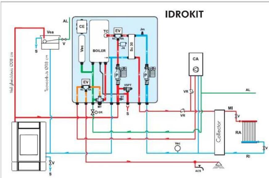
flowchart
graph TD
    A["Well checkouts Ø28 cm"] --> B["Vea"]
    B --> C["S"]
    C --> D["Toothecbits Ø18 cm"]
    D --> E["VEa"]
    E --> F["V"]
    F --> G["CE"]
    G --> H["BOILER"]
    H --> I["TC"]
    I --> J["EV"]
    J --> K["SC 30"]
    K --> L["Jm"]
    L --> M["P"]
    M --> N["P"]
    N --> O["VSPT"]
    O --> P["ST"]
    P --> Q["S"]
    Q --> R["MT"]
    R --> S["OR"]
    S --> T["CA"]
    T --> U["Collector"]
    U --> V["MI"]
    V --> W["RA"]
    W --> X["RI"]
    X --> Y["v"]
    Y --> Z["ACB"]
    Z --> AA["S"]
    AA --> AB["V"]
    AB --> AC["VR"]
    AC --> AD["AL"]
    AD --> AE["VA"]
    AE --> AF["VA"]
    AF --> AG["VA"]
    AG --> AH["VA"]
P: Pomp (circulator)
RA: Radiators
natural_image
Industrial piping and valve assembly (no visible text or symbols)PAKKET 5 cod. 280590
EVOORBEELD VAN EEN HYDRAULISCHE INSTALLATIE VOOR INBOUWHAARD MET PRODUCTIE VAN WARM TAPWATER
MET GEBRUIK VAN
PAKKET 6
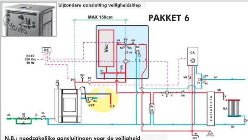
flowchart
graph TD
    A["BE"] --> B["RETE 230 Vac 50 Hz"]
    B --> C["Max 150cm"]
    C --> D["VEC"]
    D --> E["CA"]
    E --> F["CO2"]
    F --> G["COLLETTOR"]
    G --> H["RA"]
    H --> I["RJ"]
    I --> J["ACS"]
    J --> K["VA"]
    K --> L["AF"]
    L --> M["VR"]
    M --> N["SC 30"]
    N --> O["V"]
    O --> P["V"]
    P --> Q["V"]
    Q --> R["VR"]
    R --> S["SC 20"]
    S --> T["VA"]
    T --> U["VA"]
    U --> V["VA"]
    V --> W["VA"]
    W --> X["VA"]
    X --> Y["VA"]
    Y --> Z["VA"]
    Z --> AA["VA"]
    AA --> AB["VA"]
    AB --> AC["VA"]
    AC --> AD["VA"]
    AD --> AE["VA"]
    AE --> AF["VA"]
    AF --> AG["VA"]
    AG --> AH["VA"]
    AH --> AI["VA"]
    AI --> AJ["VA"]
    AJ --> AK["VA"]
    AK --> AL["VA"]
    AL --> AM["VA"]
    AM --> AN["VA"]
    AN --> AO["VA"]
    AO --> AP["VA"]
    AP --> AQ["VA"]
    AQ --> AR["VA"]
    AR --> AS["VA"]
    AS --> AT["VA"]
    AT --> AU["VA"]
    AU --> AV["VA"]
    AV --> AW["VA"]
    AW --> AX["VA"]
    AX --> AY["VA"]
    AY --> AZ["VA"]
    AZ --> BA["VA"]
    BA --> BB["VA"]
    BB --> BC["VA"]
    BC --> BD["VA"]
    BD --> BE["VA"]
    BE --> BF["VA"]
    BF --> BG["VA"]
    BG --> BH["VA"]
    BH --> BI["VA"]
    BI --> BJ["VA"]
    BJ --> BK["VA"]
    BK --> BL["VA"]
    BL --> BM["VA"]
    BM --> BN["VA"]
    BN --> BO["VA"]
    BO --> BP["VA"]
    BP --> BQ["VA"]
    BQ --> BR["VA"]
    BR --> BS["VA"]
    BS --> BT["VA"]
    BT --> BU["VA"]
    BU --> BV["VA"]
    BV --> BW["VA"]
    BW --> BX["VA"]
    BX --> BY["VA"]
    BY --> BZ["VA"]
ACS: Warm tapwater
AF: Koud water
P: Pomp (circulator)
RA: Radiators
natural_image
Industrial equipment setup with pressure vessel, tubing, and control panel (no visible text or symbols)PAKKET 6 cod. 280600
R reg. opening driewegklep (KIT 1 - 3 - 5 - 6)
R reg. werking circulators (PAKKET 2)
RIC interne afstelling pomp
S keuzeschakelaar MAN-OFF-AUTO
SP controlelamp pomp
| ITALIANO | ENGLISH | FRANÇAIS | ESPAÑOL | DEUTSCH | NEDERLANDS | pz. | KLIMA base | WARM base | |||
| BASE | CS | BASE | CS | ||||||||
| 1 | Boscarenia in glasia | Cost iron base | Base en fonte | Base de fundación | Socket aus Guas | Gietkizen onderkontel | 1 | 292320 | 292320 | 292320 | 292320 |
| 2 | Struttura metallica | Metal frame | Structure métallique | Estructura metallica | Metellstruktur | 1 | 293013 | 294463 | 293013 | 294463 | |
| 3 | Distanzioli per top | Spacers for top | Entrotios pour haut | Distancioderos para tapa | Abstandshaltor für Oborteil | Opvirklingen voor bovonkant | 4 | 295980 | 295980 | 295990 | 295990 |
| 4 | Top allaire carbonico stava. Controllos corona | Top soapstone Iod ceramic tiles, Annoor ceramic tiles | Top plano allaire carbonico sava. Controllos sava. | Top plano allaire carbonico sava. Controllos sava. | Oborteil Nola unan Serpentina Role Teramica Controllos keramik | Bovonkant Sotela per Rode teramik | 1 | 213580 | 213580 | 293440 293450 | 293440 293450 |
| 5 | Profilin al alumina | Aluminium bar | Profilis en aluminium | Perfiles de aluminium | Aluminium profile | Aluminium pristelen | 4 | 293810 | 293810 | 293810 | 293810 |
| 6 | Pannello sostegno rivestimento | Covering support panel | Paneau support revêtement | Panel de soporte revestimento | Stratoursele für Verkleidung | Steunpannel bedecking | 2 | 645380 | 645380 | 645380 | 645380 |
| 7 | Franco grande in glisa | Large cast iron slide | Flange grand en fonte | Lacia grande on fundación | Crosser Schotteli aus Guas | Grote giolifizuron zitlont | 2 | 292330 | 292330 | 292330 | 292330 |
| 8 | Basiliclla laterale carbonica Barko | Side tile Soapstone And ceramic tiles And ceramic tiles | Ceramic oraltral Perde allaire Ceramic oraltral | Place toterio Padro allair Ceramic oraltral | Settiche Flavan Nutrigeni Serpentina Role Teramica Controllos keramik | Ziploaya Sotekimen Role Teramik | 4 | 292910 | 292910 | 292960 292990 | 292960 292980 |
| 9 | Supporto fissaggio | Side tile fastening support | Support fixation carneu latoral | Supporte fijación placa latoral | Aufhängung solitiche Keromik | Bevoigtigationszun zijpiactje | 4 | 294210 | 294210 | 294210 | 294210 |
| 10 | Pianarita frontale Cerra allaire Ceramico rossa Corramico amora | Chore tile Soapstone And ceramic tiles And ceramic tiles | Carneau frontale Cerra allaire Ceramico rouge Carneau anlare | Place frontal Spade allaire Ceramico rug Carneau anlare | Front fliso Nutrigeni Serpentina Role Teramica Bersteln Keromik | Voorloctojo Rood teramik Antser keramik | 2 | 292900 | 292900 | 292900 292990 | 292950 292990 |
| 11 | Supporto fissaggio piastrella frontale | Front tile fastening support | Support fixation carneu frontal | Supporte fijación placa frontal | Aufhängung Front Flisse | Bevoigtigationszum voorplazje | 2 | 293710 | 293710 | 293710 | 293710 |
| 12 | Plasino speziione scambiotore | Heel exchanger inspection tile | Plaque insertion échangeur | Place inspección intercambiódor | Inspeletansplatte des Warmelauschers | Inspeletansplatte warmielwisselaor | 1 | 295570 | 295570 | 295570 | 295570 |
| 13 | Semando fumi | Smoke shutter | Rideau furnées | Componerta remos | Rauchgasklapoo | Rookluk | 1 | 293543 | 293543 | 293543 | 293543 |
| 14 | Asia serranda fumi | Smoke shutter rod | Tige ridreau furnées | Borna comperta humos | Rauchgasklapoe Regelungsatz | Stang roosluk | 1 | 293580 | 293580 | 293580 | 293580 |
| 15 | Profunga asta semanda fumi | Smoke shutter rod extension | Rollonge tige ridreau furnées | Extension borro compuerto humos | Verlängerung des Regelungsatzes | Verlengstk stang roosluk | 1 | 293610 | 293610 | 293610 | 293610 |
| 16 | Convogliotoro aria | Air conveyor | Conveyeur air | Transportador aire | Luthumlenker | Luchtulnel | 1 | 293653 | 293653 | 293653 | 293653 |
| 17 | Deflector | Boffe | Deflector | Deflector | Deflector | Deflector | 1 | 293700 | 293700 | 293700 | 293700 |
| 18 | Semanda aria | Air shutter | Rideau air | Componerta aire | Sekwardenhegelung | Luchtulk | 1 | 295510 | 295510 | 295510 | 295510 |
| 19 | Porologna | Wood guard | Para-büches | Protección leno | Holzschutz | Houtwaring | 1 | 293790 | 293790 | 293790 | 293790 |
| 20 | Telea amina | Door frame | Chélessa porte | Rostidor puerto | Turrahmen | Frame deutite | 1 | 288090 | 288090 | 288090 | 288090 |
| 21 | Pemo superiore | Upper pin | Pivot supérieur | Perno superior | Oberer Zapfen | Spil boven | 1 | 270560 | 270560 | 270560 | 270560 |
| 22 | Cramiazione ∅ 14 | ∅ 14 gasket | Craniture ∅ 14 | Empoquetadora 14 ∅ | Dichtung ∅ 14 | Parking ∅ 14 | L=1,70 m | 273810 | 273810 | 273810 | 273810 |
| 23 | Malla ornina | Door spring | Ressort porte | Muella puerta | Tufelder | Veer deutite | 1 | 288380 | 288380 | 288380 | 288380 |
| 24 | Plasmina comiera | Hinge plate | Plaque chromière | Place bisogra | Abschlussplächen | Ploartje schornier | 1 | 288370 | 288370 | 288370 | 288370 |
| 25 | Pamo comiera inferioro | Lower hinge pin | Pivot chromière inferioro | Pamo bisogra inferioro | Zazfon anteros Abschlussplächen | Spil schemier onder | 1 | 289060 | 289060 | 289060 | 289060 |
| 26 | Cuernizione 8x1 adesiva | 8 x 1 adhesive gasket | Craniture 8 x 1 adhesiva | Empoquetadora 8 x 1 adhesiva | Selbstlebanche Dichlung 8 x 1 | Plaksvaiking 8 x 1 | L=1,40 m | 188140 | 188140 | 188140 | 188140 |
| 27 | Fermavetro | Grass holder | Ambr de varre | Protección viérrio | Scheibenhalterungen | Glassbladking | 5 | 288390 | 288390 | 288390 | 288390 |
| 28 | Cuernizione 8x2 adesiva | 8 x 2 adhesive gasket | Craniture 8 x 2 adhesiva | Empoquetadora 8 x 2 adhesiva | Selbstlebanche Dichlung 8 x 2 | Plaksvaiking 8 x 2 | L=0,70 m | 173050 | 173050 | 173050 | 173050 |
| 29 | Veiro | Grass | Veiro | Vidrio | Turglas | Glas | 1 | 199050 | 199050 | 199050 | 199050 |
| 30 | Maniglia | Handlo | Pagna | Manija | Türgfrt | Handvat | 1 | 288333 | 288333 | 288333 | 288333 |
| 31 | Aggiangio manglia | Handle loader | Crochet polignée | Enganche monita | Türgfrhlöhenung | Hsak handvat | 1 | 694280 | 694280 | 694280 | 694280 |
| 32 | Antina complete | Complete door | Porte complete | Puerta completa | Tor komplett | Complet euerje | 1 | 295600 | 295600 | 295600 | 295600 |
| 33 | Plano fuoco | Hoorth | Plan du feu | Pono fuogo | Brankkommer Boden | Vuroplot | 1 | 293530 | 293530 | 293530 | 293530 |
| 34 | Griglia cerere | Ash grate | Grille cerdes | Rejillo cerclusa | Aschentop-Gitter | Ascoaster | 1 | 293800 | 293800 | 293800 | 293800 |
| 35 | Retro | Rear | Das | Parle frazero | Rückwand | Aschlerkart | 1 | 293720 | 293720 | 293720 | 293720 |
| 36 | Termometro acqua | Water thermometer | Thermometro eau | Termometro agua | Wasserthermometer | Waterhormometer | 1 | 429680 | 429680 | 429680 | 429680 |
| 37 | Monopola regolizane aria primario | Primary air regulation knob | Bauxion de réglage air primaire | Markieia regulación aire primario | Prindrußregelungsknupf | Steinops primaire Licht | 1 | 278320 | 278320 | 278320 | 278320 |
| 38 | Termoregolatore aria combustione | Combustion air thermoregulator | Thermoregulateur air combustion | Termoregulateur air combustion | Thermoregler Veränderungsluft | Warmterogolar verbrandingslucht | 1 | 429690 | 429690 | 429690 | 429690 |
| 39 | Profile chiusura termoregolatore | Thermoregulator closing bar | Profit fermenture thermoregulateur | Profit fermente termoregulator | Abschlussprofil Thermoraglier | Sluitrofoel warmoroglaor | 1 | 285810 | 285810 | 285810 | 285810 |
| 40 | Guernizione 10x2 | 10 x 2 gasket | Garniture 10x2 | Empoquetadora 10 x 2 | Dichtung 10 x 2 | Packing 10 x 2 | L=0,60 m | 425810 | 425810 | 425810 | 425810 |
| 41 | Supporto termoregolatore | Thermoregulator support | Supoact thermoregulateur | Supoct thermoregulateur | Thermoreglerwährhängung | Strom warmoroglaor | 1 | 281120 | 281120 | 281120 | 281120 |
| 42 | Serpentina | Coil | Serpentin | Serpentin | Sicherheitswämetauscher | Spinrol | 1 | 293160 | 293160 | ||
| 43 | Raccordetta 3 patti | Pipe fittings (3 pcs.) | Raccords (3 pieces) | Uniones (2 pts) | Fittinge (3 Sk.) | Verbindungslementen (3 ruka) | 1 | 790960 | 790960 | ||
| 44 | Volvole scorico termico | Host discharge valve | Soupope evacuation thermique | Vóvlula de descarga térmica | Thermische Aldoufachering | Thermische aldoorklap | 1 | 295280 | 295280 | ||
| 45 | Curva 3/4 M/F | 3/4 M/F bond | Coude 3/4 M/F | Curva 3/4 M/F | Bogen 3/4 Mullo/Flansch | Bocht 3/4 M/V | 1 | 276280 | 276280 | ||
| 46 | Riculazione 3/4 M - 1/2 F | 3/4 M - 1/2 F pipe reducer | Reducieur 3/4 M - 1/2 F | Reducción 3/4 M - 1/2 F | Reduzierungstück 3/4 M - 1/2 F | Verkeiring 3/4 M / V/V | 1 | 283780 | 283780 | ||
| 47 | Attizzatorio | Polar | Attizior | Attizidor | Glutosison | Aspot | 1 | 253970 | 253970 | 253970 | 253970 |
| 48 | Voschello cerere | Ash drawer | Basià cerides | Cadin de la cerixa | Ascheschubich | Aslide | 1 | 230610 | 230610 | 230610 | 230610 |
| 49 | Giarto | Grove | Gout | Gurote | Handschun | Handsochen | 1 | 3350 | 3350 | 3350 | 3350 |
| 50 | Porta birbo | Support drill | Porta birbe | Porta bombilla | Lamsonflüssung | Balouder | 1 | 284100 | 284100 | 284100 | 284100 |
| 51 | Franco sinistro focolorse scamoxles | Large left firebox scamoxles | Flange gauche loyer scamoxles | Lucia siquiera hogar scamoxles | Links Feuverrum-Soltenollement aus Scamoxles | Scamoxles linkerrijant vanmaard | 1 | 624040 | 624040 | ||
| 52 | Fermo focolare postoreto | Catch back firebox | Anrete layer posterior | Protección hogar posterior | Hinterer Feuverrum-Halter | Blockering ochter vanmaard | 1 | 624880 | 624880 | ||
| 53 | Franco cistro focolare scamoxles | Large right firebox scamoxles | Flange droite loyer scamoxles | Lucia derecho hogar scamoxles | Roctos Feuverrum-Soltenollement aus Scamoxles | Scamoxles rechnerissant vanmaard | 1 | 624030 | 624030 | ||
| 54 | Stoffa fissoglio scamoxles | Stirup fastening scamoxles | Elter fixation scamoxles | Abrozadora de fijación scamoxles | Helletbügel aus Scamoxles | Scamoxles bevestigingsbuegel | 1 | 380690 | 380690 | ||
| 55 | Viti aurifattanti M4,2x9 | Self-topping screws M4,2x9 | Vis cutofflogate M4,2x9 | Tomillos autoroscantes M4,2x9 | Selbanscheidende Schraube 4,2x9 | Zelfborgende schroeven M4,2x9 | 2 | 29600 | 29600 | ||
| --- | Set folocore scamoxles | Firebox scamoxles set | Set série loyer scamoxles | Set hogar scamoxles | Set Scamoxles Olenikammer | 1 | 624670 | 624670 | |||
| --- | Set serie patro allaire | Soapstore set | Set série pierre allaire | Set serie padre allaire | Naturestein-Serpinita Komplett-Serie | 292850 | 292850 | ||||
| --- | Set serie ceramico rosso | Iod ceramic set | Set série ceramico rouge | Set serie ceramico roja | Roto Keramik Kompott-Sorio | 292890 | 292890 | ||||
| --- | Set serie ceramica ambra | Amber ceramic set | Set série ceramica ambra | Set serie ceramica ambra | Borsalmiorkoramik Komplett-Sorio | ||||||
KLIMA e WARM con scaldavivande / KLIMA e WARM with hotplate / KLIMA e WARM avec chauffe-plats / KLIMA y WARM con calientaplatos / KLIMA und WARM mit warmhalteplatte / KLIMA en WARM met voedselwarmhouder
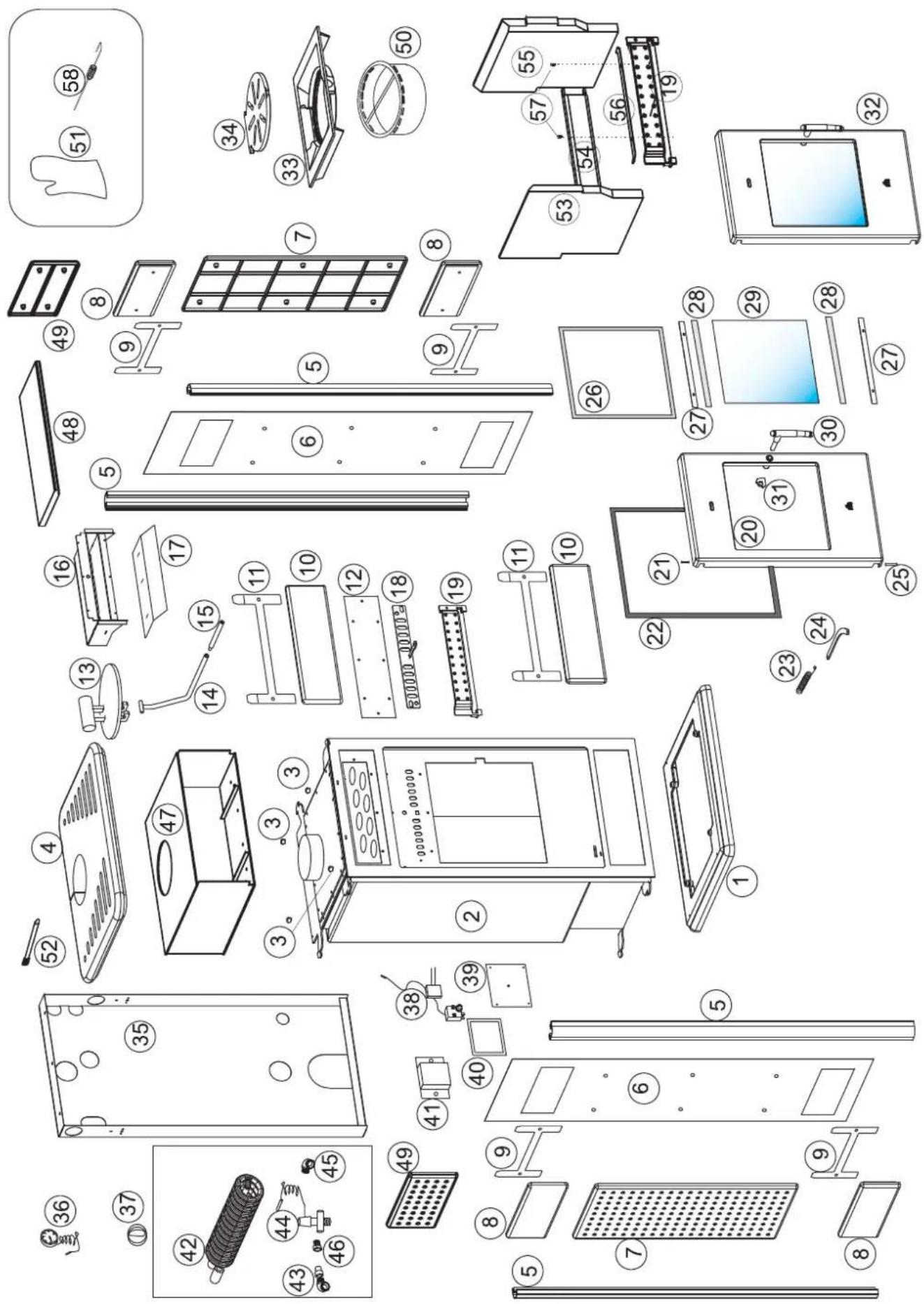
| ITALIANO | ENGLISH | FRANÇAIS | ESPAÑOL | DEUTSCH | NEDERLANDS | pz. | KLIMA scaldavivande | WARM scaldavivande | |||
| BASE | CS | BASE | CS | ||||||||
| 1 | Boscamento in glasia | Cost iron base | Base en fonte | Base de fundación | Società aus Gucci | Girotturen onderkant | 1 | 292320 | 292320 | 292320 | 292320 |
| 2 | Struttura metallica | Metal frame | Structure métallique | Estructura metallica | Metallismotlar | Metalien struttura | 1 | 293013 | 294463 | 293013 | 294463 |
| 3 | Distonelli per top | Spacera for top | Entelloises pour haut | Distanciadora para tapo | Abstandshelter für Oberteil | Cupulingen voor bovenkant | 4 | 295980 | 295980 | 295990 | 295990 |
| 4 | Pra. Chro. olloro Ceramico ramp. Ceramico armola | Spa. Notatione and ceramic tiles, Amber ceramic tiles | Ligare allaire CeramicONE rouge, Amber ceramic tiles | Trapp. Ollor Ceramico agar, Amber ceramic tile | Cherolo Noyglim - Soprantino Role Geramik, Amber ceramic tile | Bonnikoni Wood ceramik, Amber ceramic tile | 111 | 213580 | 213580 | 293140293140 | |
| 5 | Profilin al alluminio | Aluminium bar | Profilis on alluminio | Portilles de alluminio | Aluminiumportilla | Aluminium portilion | 4 | 295660 | 295660 | 295660 | 295660 |
| 6 | Panrello scalegra revestimento | Covering support panel | Panremau support restitmental | Panel support investmenta | Sützorazelle für Verbindung | Steupspanel becklcien | 2 | 645380 | 645380 | 645380 | 645380 |
| 7 | Fianca grande in grisa | Large cast iron side | Flare grand on fonte | Lado grande on fundacion | Grosser Schottell aus Gucci | Grote giottiparon zijlont | 2 | 292330 | 292330 | 292330 | 292330 |
| 8 | Kaptralga laterale Patra olloro Ceramics rossa Ceramics armola | Side tile Spatipline Steel ceramic tiles, Amber ceramic tiles | Carrocay cistral Opere allaire CeramicONE rouge, Amber ceramic tile | Slago lateral Serra Solar Carriolite Alog, Carriolite Blandar | Sethliche Flesso Neutrisch - Soprantino Rolo, Soppiolo, Rettelsan Karamik | Zuplatio Plessor Ramasile, Amber Keronimik | 444 | 292910 | 292910 | 292960292980 | |
| 9 | Support fisaggio plastrella laterale | Side tile fastening support | Support fixation carrea latire | Support fijación placa latra | Aufhängung satifiche Keramik | Bevestigungssteun zijlplante | 4 | 294210 | 294210 | 294210 | 294210 |
| 10 | Serraglia terredale Patra olloro Ceramics rossa Ceramics armola | Front tile Spatipline Spatipline, Amber ceramic tiles | Carreau vorsat Piano allaire CeramicONE rouge, Amber ceramic tile | Scrap. Nepal Carriolite Elogia, CeramicONE arbar | Front risso Frastogla Soprantino Borristol Karamik, Bornistol Karamik | Vossipazione Torino Soprimo, Bornistol Karamik, Amber Keronimik | 222 | 292900 | 292900 | 292950292990 | |
| 11 | Support fisaggio plastrella frontola | Front tile fastening support | Support fixation carrea frontal | Support fijación placa frontal | Aufhängung Front Flose | Bevestigungssteun voorlartoje | 1 | 293710 | 293710 | 293710 | 293710 |
| 12 | Pastra ispezione scamblotora | Host exchanger inspection file | Plaque inspection echangeur | Placa inspección intercomitador | Inspeitatione olos Wärmtotsuchers | I-spectieplantej warmtouhwssolcar | 1 | 295570 | 295570 | 295570 | 295570 |
| 13 | Serranda fumi | Smoke shutter | Rideau furnées | Campuerta humos | Rauschgasklasse | Roasiluk | 1 | 293543 | 293543 | 293543 | 293543 |
| 14 | Astra serranda fumi | Smoke shutter rod | Tage ridouu furnos | Borna compuerte humos | Rauchgasklasse-Regulngastob | Stang roasiluk | 1 | 293590 | 293590 | 293590 | 293590 |
| 15 | Prolunga radio semanda fumi | Smoke shutter rod extension | Rollonge lige idleau furnées | Extension borro compuerte humos | Verfängerung des Regelungsstabes | Verlengitruk stang roasiluk | 1 | 293610 | 293610 | 293610 | 293610 |
| 16 | Convogliatore orla | Air conveyor | Conveyet air | Transportador aire | Lufumenlier | Luclturnel | 1 | 293653 | 293653 | 293653 | 293653 |
| 17 | Defetore | Buffie | Deflacteur | Deflector | Deflector | Deflector | 1 | 293700 | 293700 | 293700 | 293700 |
| 18 | Serranda orla | Air shutter | Rideau air | Compuerta aire | Seundarvirkregelung | Luchlik | 1 | 295510 | 295510 | 295510 | 295510 |
| 19 | Porolegna | Wood guard | Pane-Büches | Protección larlo | Holzacruz | Houtwering | 1 | 293790 | 293790 | 293790 | 293790 |
| 20 | Tolao anino | Door fromo | Chössis porto | Bostidor puerto | Törtmton | Frame dourjo | 1 | 288090 | 288090 | 288090 | 288090 |
| 21 | Perro superiore | Upper pin | Pivot supérieur | Perro superior | Obener Zapfen | Spil acven | 1 | 270560 | 270560 | 270560 | 270560 |
| 22 | Guarnione ∅ 14 | ∅ 14 gasket | Garniture ∅ 14 | Empoquetadora 14 ∅ | Dichtung ∅ 14 | Pasking ∅ 14 | L=1,70 m | 273810 | 273810 | 273810 | 273810 |
| 23 | Molla ornina | Door sorting | Resson porto | Nuella puerta | Turkctor | Voor dourto | 1 | 288380 | 288380 | 288380 | 288380 |
| 24 | Piardina cerriera | Air shutter | Plaque chiamère | Placa bisagra | Abschlussplättchen | Plectrje scharler | 1 | 288370 | 288370 | 288370 | 288370 |
| 25 | Permo cerriera inferiore | Wood guard | Pivot chiamère inférieur | Permo basagra inferior | Zapfen unteres Abschlussplättchen | Spil scharler ander | 1 | 289060 | 289060 | 289060 | 289060 |
| 26 | Cuornazione Bx1 adesiva | Door fromo | Garniture 8 x 1 adhesive | Empoquetadora 8 x 1 adhesiva | Selbstlebende Dichtung 8 x 1 | Plakpoaking 8 x 1 | L=1,40 m | 188140 | 188140 | 188140 | 188140 |
| 27 | Formavato | Upper pin | Aridé do verre | Protección vidrio | Scheibenholterungen | Glossblockering | 2 | 288390 | 288390 | 288390 | 288390 |
| 28 | Guornazione Bx2 adesiva | ∅ 14 gasket | Garniture 8 x 2 adhesive | Empoquetadora 8 x 2 adhesiva | Selbstlebende Dichtung 8 x 2 | Plakpoaking 8 x 2 | L=0,70 m | 173050 | 173050 | 173050 | 173050 |
| 29 | Vetro | Door sorting | Vetro | Vidrio | Turglas | Glas | 1 | 199050 | 199050 | 199050 | 199050 |
| 30 | Maniglia | Hinge plate | Poignée | Manija | Turgili | Handval | 1 | 288333 | 288333 | 288333 | 288333 |
| 31 | Agglioio manglia | Lower hinge pin | Crochet polgnée | Enganche monita | Törg-Holtsung | Hook handvol | 1 | 694280 | 694280 | 694280 | 694280 |
| 32 | Antina completa | 8 x 1 adhesive gasket | Porte complete | Puerta complete | Tür komplet | Compost courje | 1 | 295600 | 295600 | 295600 | 295600 |
| 33 | Piano luova | Glass holder | Plan du feu | Piano fuego | Berrenkommer Boden | Vuropokat | 1 | 293530 | 293530 | 293530 | 293530 |
| 34 | Griglia cinere | 8 x 2 adhesive gasket | Grille cerides | Rejillo ceriza | Ascherrsoff-Gitter | Avrooster | 1 | 293800 | 293800 | 293800 | 293800 |
| 35 | Retro | Glass | Dos | Porte trascero | Rückwand | Achtorkont | 1 | 293720 | 293720 | 293720 | 293720 |
| 36 | Termamento acqua | Handle | Thermometre eau | Termometre agua | Wasserthermometer | Waterthermometer | 1 | 429680 | 429680 | 429680 | 429680 |
| 37 | Manapala regolazione aria primario | Handle fastener | Bouton de réglage air primaire | Manieta de regulación aire primario | Primarulregelungsknopf | Steinknap primaire Licht | 1 | 278320 | 278320 | 278320 | 278320 |
| 38 | Termoregolatora aria combustione | Complete door | Thermoregolatora air combustion | Termoregolador aine combustion | Thermorogler Vorrantungssturt | Warmerogolor vorbrandingslucht | 1 | 429690 | 429690 | 429690 | 429690 |
| 39 | Pazilia chiusure termoregolatora | Heath | Profil fermetaire thermoregolator | Perfil cierte termoregulator | Abschlussprofil Thermoregler | Sulfotrefel warmeregelator | 1 | 285810 | 285810 | 285810 | 285810 |
| 40 | Guornione 10×2 | Ash grate | Garniture 10×2 | Empoquetadora 10 x 2 | Dichtung 10 x 2 | Packing 10 x 2 | L=0,60 m | 425810 | 425810 | 425810 | 425810 |
| 41 | Supporto termoregolatora | Thermoregulator support | Support thermoregoluteur | Supporte termoregulator | Thermoreglerwährigung | Steun warmeregelator | 1 | 281120 | 281120 | 281120 | 281120 |
| 42 | Serpentinia | Cell | Serpentin | Serpentin | Sicherheitswärmetauscher | Sprinel | 1 | 293160 | 293160 | ||
| 43 | Raccocleria 3 pazzi | Pipe fittings (3 pcs.) | Raccords (3 pieces) | Unionies (3 pcs.) | Fritinge (3 Stk.) | Verbindsgalemten (3 staks) | 1 | 290960 | 290960 | ||
| 44 | Valvolo scorico tornico | Hotel discharge valve | Soupoe evacuation thermique | Valvula do descarga térmica | Thermische Aloksüferung | Thermische afworklop | 1 | 296280 | 296280 | ||
| 45 | Curva 3/4 M/T | 3/4 M/T beerd | Coudé 3/4 M/T | Curva 3/4 M/T | Bogen 3/4 Multi/M/Vance | Bach 3/4 M/V | 1 | 276280 | 276280 | ||
| 46 | Ricuzione 3/4 M - 1/2 F | 3/4 M - 1/2 F pioo reducer | Riducourt 3/4 M - 1/2 F | Reducción 3/4 M - 1/2 F | Reduzierungssatz 3/4 M - 1/2 F | Vorklining 3/4 M = 1/V | 1 | 283780 | 283780 | ||
| 47 | Scoldovirando | Hotpotio | Chauffo-pots | Callanaplatos | Warmthofbach | Voocolswarmhouser | 293730 | 293730 | |||
| 48 | Plastinella scaldavivende: Pierra allaire Ceramics rossa | Hotpotile tile Soapstone Red ceramic tiles Amber ceramic tiles | Carreaux chaille plots Pierre allaire Céromique rouge Amber ceramic tile | Placo collentaplatos Piedro allair Céromique rouge Amber ceramic tile | Fliesen fur Warmhaltelach Naturesin-Serpenteiro Role Keramik Berriela Keramik | Plache voelselvarnhouser Specken Roof ceramiek Annel keramiek | |||||
| 49 | Fianca piccolo in ghista | Small cost iron side | Flanc porti en fonte | Latia pesuñón en fundición | Kleines Sahorteil aus Guss | Kleine gelizieren zijkani | |||||
| 50 | Vouchetta cinere | Ash drawer | Bao à cerides | Cajón de la cenista | Ascheschubich | Aslade | |||||
| 51 | Cuanto | Glove | Gont | Guente | Handschuh | Handschuh | |||||
| 52 | Porta oubo | Support drill | Porta bubo | Porta bombilla | Laomoeklossung | Bohoudor | |||||
| 53 | Fianca sinistro focolare scamoxles | Large left firebox scamoxles | Flanc gauche loyer scamoxles | Lada suqueando hogar scamoxles | Links Ferreiraum-Seitenlement aus Scamoxles | Scamoxles linkersijnant voorraard | |||||
| 54 | Fermo focolare postorio | Catch back knockbox | Arrate layer asalneur | Protecation nogar posterior | Hinterer Ferreiraum-Hatter | Blokdoring ochrar voorraard | |||||
| 55 | Fianca desire focolare scamoxles | Large right firebox scamoxles | Flanc droite fogor scamoxles | Lada derecho hogar scamoxles | Recitos Ferreiraum-Seitenlement aus Scamoxles | Scamoxles rechnerijant voorraard | |||||
| 56 | Staffa risaggio scamoxles | Shrup flistening scamoxles | Elter fixation scamoxles | Abrozadora de fijación scamoxles | Rechtes Ferreiraum-Seitenlement aus Scamoxles | Scamoxles bevestigtingsbuigel | |||||
| 57 | Vitis autoliattanti M4,2x9 | Self-hopping screws M4,2x9 | Vis cutoffstage M4,2x9 | Tamillos utoromascantes M4,2x9 | Selabschendinde Schraube M4,2x9 | Zeiborgende schroeven M4,2x9 | |||||
| 58 | Allizataola | Faker | Allizer | Allizer | Culteisen | 253970 | |||||
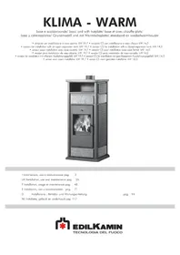
- BY-PASS FUMI AUTOMATICO
- CHIUSURA AUTOMATICA ANTINA
- Anno
- - Canale da fumo
- SAFETY INFORMATION:
- THE BOILER-STOVE MUST NEVER BE RUN WITHOUT WATER IN THE SYSTEM.
- "WATERLESS" IGNITION DAMAGES THE BOILER-STOVE.
- Declaration of conformity
- Declares under its own responsibility as follows:
- YEAR OF MANUFACTURE: Ref. Data nameplate
- SERIAL NUMBER: Ref. Data nameplate
- KLIMA - WARM UNI EN 13240:2006
- KLIMA/CS - WARM/CS UNI EN 13240:2006
- Also declares as follows:
- NOTES on fuel:
- OPERATING PRINCIPLE/TECHNICAL DATA
- ,PRIMARY AIR REGULATION (for combustion)
- AUTOMATIC SMOKE BY-PASS VALVE
- -SECONDARY AIR REGULATION
- AUTOMATIC DOOR CLOSURE
- GENERAL SAFETY REGULATIONS
- ONLY BOILER-STOVES WITH A COIL OPERATED BY A HEAT DISCHARGE VALVE MAY BE INSTALLED ON SYSTEMS WITH A CLOSED EXPANSION TANK.
- 1st year
- KLIMA e WARM
- for installation with an OPEN TANK
- NB:
- KLIMA/CS e WARM/CS
- for installation with an CLOSED TANK
- LOCATION
- AIR INTAKE
- - SMOKE DUCT
- • SMOKE OUTLET
- • BUTTERFLY VALVE
- • CHIMNEY
- INSTALLATION INFORMATION
- COMPATIBILITY CHECK WITH OTHER DEVICES
- FIRE SAFETY DISTANCES
- WATER CONNECTIONS:
- THE BOILER-STOVE MUST NEVER BE RUN WITHOUT WATER IN THE SYSTEM. "WATERLESS" IGNITION DAMAGES THE BOILER-STOVE.
- Water treatment
- PRACTICAL NOTE
- Boiler-stove installation in an open system:
- Boiler-stove installation with closed expansion tank:
- External covering assembly for BASIC WARM /KLIMA
- External covering assembly for WARM /KLIMA with HOTPLATE
- CERAMIC SETS
- BASIC WARM / KLIMA
- WARM / KLIMA with hotplate
- FIREBOX SCAMOLEX SET (cod. 624670)
- INSTALLATION SEQUENCE:
- Practical advice
- Fuel and heating value
- During the combustion process
- Cleaning the glass pane
- Cleaning the flue
- Maintenance
- Failure to perform maintenance shall forfeit the guarantee.
- FAQ
- CHECK LIST
- Read the entire specifications before using this list
- SELECTOR FUNCTIONS
- electronic regulator
- IMPORTANT ADVICE REGARDING THE INSTALLATION
- Compliance with regulations regarding the earth connection is fundamental for the safety of people.
- LEGEND
- Operation
- - Control device:
- - Protection device
- (acoustic alarm system):
- - Power supply device (circulation system):
- - Operation device (setting system):
- Attention:
- Positioning
- Installation
- The power supply must be disconnected from the mains and the AUTO-OFF-MAN selector (S) must be in the OFF position when all these operations are carried out.
- DÉCLARATION DE CONFORMITÉ
- BY-PASS FUMÉES AUTOMATIQUE
- FERMETURE AUTOMATIQUE PORTE
- • CONDUIT DES FUMÉES
- Fonctionnement
- BY-PASS AUTOMÁTICO DE HUMOS
- SET CERÁMICAS
- AUTOMATISCHE ABGASKLAPPE
- - Rauchkanal
- AUTOMATISCHE BY-PASS ROOK
- AUTOMATISCHE AFSLUITING DEURTJE
- - Rookkanaal
- VOORBEELD VAN EEN HYDRAULISCHE INSTALLATIE VOOR INBOUWHAARD MET PRODUCTIE VAN WARM TAPWATER+WANDKETEL MET GEBRUIK VAN PAKKET N3
Brand : EDILKAMIN
Model : Warm
Category : Frying Pan