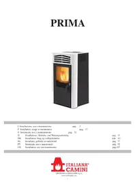
PRIMA - Frying Pan EDILKAMIN - Free user manual and instructions
Find the device manual for free PRIMA EDILKAMIN in PDF.


| Product Type | Wood pellet stove |
| Brand | Edilkamin |
| Model | PRIMA |
| Fuel | Wood pellets (diameter 6 mm, max length 40 mm, max humidity 8%) |
| Nominal power | 7 kW |
| Reduced power | 2.4 kW |
| Nominal efficiency | 90.1 % |
| Reduced efficiency | 94.67 % |
| Hopper capacity | 15 kg |
| Autonomy | 8 to 24 hours |
| Heatable volume | 180 m³ |
| Power supply | 230 V ~ 50 Hz |
| Average power consumption | 120 W |
| Ignition power consumption | 400 W |
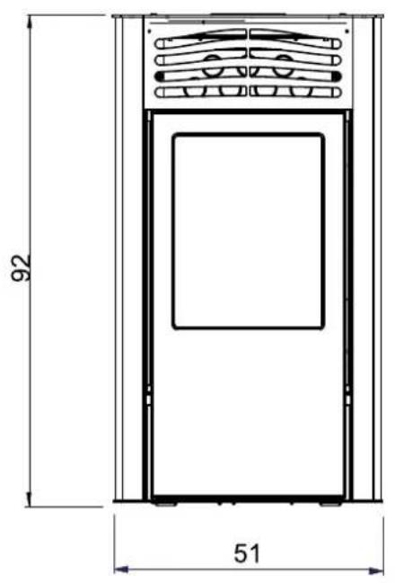
| Dimensions (H x W x D) | 92 x 51 x 51 cm |
| Weight with packaging | 120 kg |
| Flue outlet diameter | 80 mm |
| Air intake diameter | 40 mm |
| Fire safety distances | Sides and rear: 20 cm; front: 80 cm |
| Safety devices | Thermocouple, pressure switch, safety thermostat |
| Daily maintenance | Cleaning the burner pot, emptying the ash drawer |
| Annual maintenance | By an authorized technical service center (CAT) |
| Options | Remote control, multiple flue outlet kit |
| Warranty | Subject to commissioning by an authorized CAT |
Frequently Asked Questions - PRIMA EDILKAMIN
User questions about PRIMA EDILKAMIN
0 question about this device. Answer the ones you know or ask your own.
Ask a new question about this device
Download the instructions for your Frying Pan in PDF format for free! Find your manual PRIMA - EDILKAMIN and take your electronic device back in hand. On this page are published all the documents necessary for the use of your device. PRIMA by EDILKAMIN.
USER MANUAL PRIMA EDILKAMIN
natural_image
Exterior view of a white and black electric stove with visible flames inside (no text or symbols)UK Installation, use and maintenance
pag. 2
pag. 17
pag. 32
pag. 47
side 62
pag. 77
pág. 92
pag.107
Gentile Signora / Egregio Signore
fig.1
INFORMAZIONI PER LA SICUREZZA
natural_image
Close-up of a mechanical component with wires and a rectangular housing (no visible text or symbols)CARATTERISTICHE
natural_image
3D rendering of a red and gray portable device with ventilation slots and a labeled arrow pointing to its side (no text or symbols on the device itself)
USCITA FUMI
natural_image
3D cutaway view of a red and black electronic device casing with internal compartments (no text or symbols visible)natural_image
3D diagram of a red industrial device with labeled component D, showing internal components and housing (no text or symbols beyond label)COLLEGAMENTO USCITA FUMI LATERALE
natural_image
3D model of a red and black device with labeled component E, shown in figure 8 (no text or symbols on the device itself)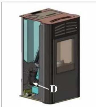
natural_image
3D cutaway view of a device casing with internal components and labeled point D (no text or symbols beyond label)COLLEGAMENTO USCITA FUMI DAL TOP
natural_image
3D rendering of a red and gray portable air conditioner unit with ventilation grilles and a chimney (no text or symbols visible)UNA VOLTA TERMITA L'OPERAZIONE DI COLLEGAMENTO DEL TUBO USCITA FUMI ALLA CANNA FUMARIA RIMONTARE IL FIANCO IN METALLO.
ISTRUZIONI D'USO
natural_image
Illustration of a red and black industrial air purifier with ventilation grilles and a lid (no text or symbols)fig.1
ISTRUZIONI D'USO
PANNELLO SINOTTICO

natural_image
3D rendering of a mechanical device with a bucket and lid, labeled '1' (no text or symbols on the main diagram)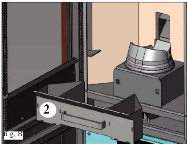
natural_image
3D mechanical assembly diagram showing a clamping device mounted on a bracket, with no visible text or symbols.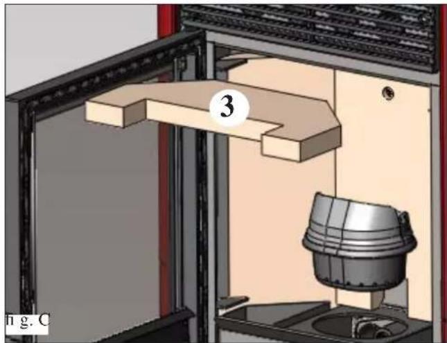
natural_image
3D diagram of a mechanical assembly with a numbered component (3) and a labeled part 'n g. C' (no readable text or symbols beyond labels)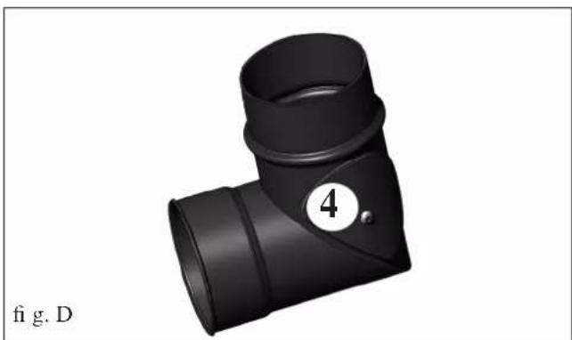
natural_image
3D rendered image of a black T-shaped pipe fitting with a numbered circle (4) and label 'fig. D' below (no text or symbols on the object itself)MANUTENZIONE
natural_image
3D CAD model of a mechanical assembly with a cylindrical component mounted on a base, shown in a view from an open frame (no text or symbols visible)fig.2
CONSIGLI PER POSSIBILI INCONVENIENTI
natural_image
Black portable vacuum cleaner with attached hose and control panel (no visible text or symbols)Bidone aspiracenere
2006/95/CEE - Directive Basse Tension
fig. 1
INFORMATIONS POUR LA SÉCURITÉ
natural_image
Close-up of a mechanical component with wires and connectors (no visible text or symbols)CARACTÉRISTIQUES
natural_image
3D rendering of a red and gray portable stove unit with ventilation grilles and a labeled arrow pointing to its side (no text or symbols on the device itself)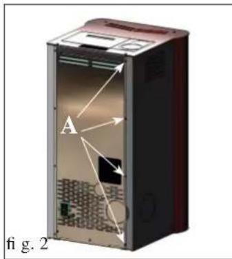
SORTIE DES FUMÉES
natural_image
Cross-sectional diagram of a red and black electronic device casing, showing internal components and housing (no text or symbols)natural_image
3D diagram of a red industrial device with internal components and labeled parts (C), no readable text or symbols beyond labels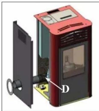
natural_image
3D diagram of a red portable device with labeled component D, showing internal components and no readable text or symbols.RACCORDEMENT SORTIE FUMÉES LATÉRALE
natural_image
3D rendering of a red and black device with labeled component E, shown in figure 8 (no text or symbols on the device itself)
natural_image
3D cutaway view of a device casing with internal components and labeled point D (no text or symbols beyond label)natural_image
3D rendering of a red and black portable stove with ventilation grilles and a chimney (no text or symbols visible)UNE FOIS L'OPÉRATION DE RACCORDEMENT DU TUYAU DE SORTIE DES FUMÉES AU CONDUIT DE CHEMINÉE TERMINÉE, REMONTER LE CÔTÉ EN MÉTAL.
MODE D'EMPLOI
natural_image
Illustration of a red and black appliance with ventilation slots and a lid (no text or symbols)fig.1

CHRONOTHERMOSTAT A PROGRAMMATION JOURNALIÈRE/HEBDOMADAIRE
natural_image
3D rendering of a mechanical device with a bucket and lid, labeled '1' (no text or symbols on the main diagram)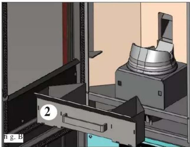
natural_image
3D mechanical assembly diagram showing a clamping device mounted on a metal bracket, with no visible text or symbols.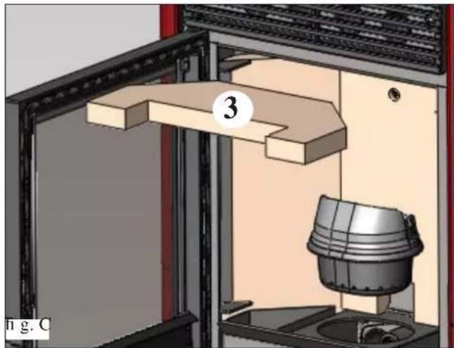
natural_image
3D technical diagram of a mechanical assembly with labeled component (no readable text or symbols)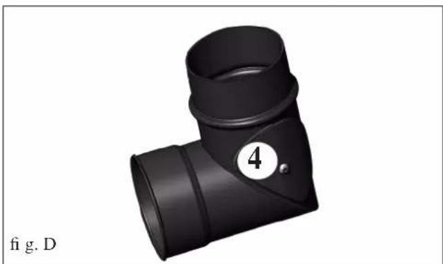
natural_image
3D rendering of a black T-shaped pipe fitting with a numbered circle (4) and label 'fig. D' below (no text or symbols on the object itself)ENTRETIEN
ENTRETIEN SAISONNIER
natural_image
3D CAD model of a mechanical assembly with a cylindrical component mounted on a base, shown in a view from an open frame (no text or symbols visible)fig.2
CONSEILS EN CAS D'ÉVENTUELS INCONVÉNIENTS
natural_image
Black and white photo of a vacuum cleaner with attached hose and control panel (no visible text or symbols)Bidon vide cendre
fig.1
natural_image
Close-up of a mechanical device with wires and components, no visible text or symbolsCARACTERÍSTICAS
natural_image
3D rendering of a red and gray portable device with ventilation slots and a labeled arrow pointing to its side (no text or symbols on the device itself)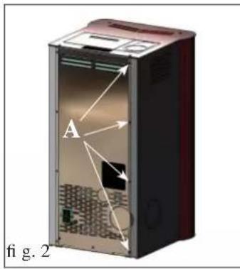
natural_image
Diagram of a device casing with labeled components and directional arrows, no readable text or symbols present.SALIDA DE HUMOS
natural_image
3D cutaway view of a red and black electronic device casing with internal compartments (no text or symbols visible)natural_image
3D diagram of a red industrial device with internal components and labeled parts (C), no readable text or symbols beyond labels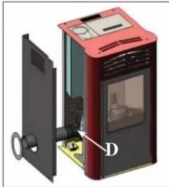
natural_image
3D diagram of a red portable device with labeled component D, showing internal components and no readable text or symbols.natural_image
3D rendering of a red and black device with labeled component E, shown in figure 8 (no text or symbols on the device itself)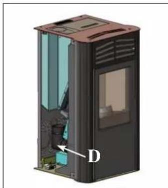
natural_image
3D cutaway view of a device casing with internal components and labeled point D (no text or symbols beyond label)natural_image
3D rendering of a red and gray portable stove with ventilation grilles and a chimney (no text or symbols visible)natural_image
Illustration of a red and black industrial oven with ventilation grilles and a lid (no text or symbols)fig.1
INSTRUCCIONES DE USO
PANEL SINÓPTICO


natural_image
3D rendering of a mechanical device with a bucket and lid, labeled '1' (no text or symbols on the main diagram)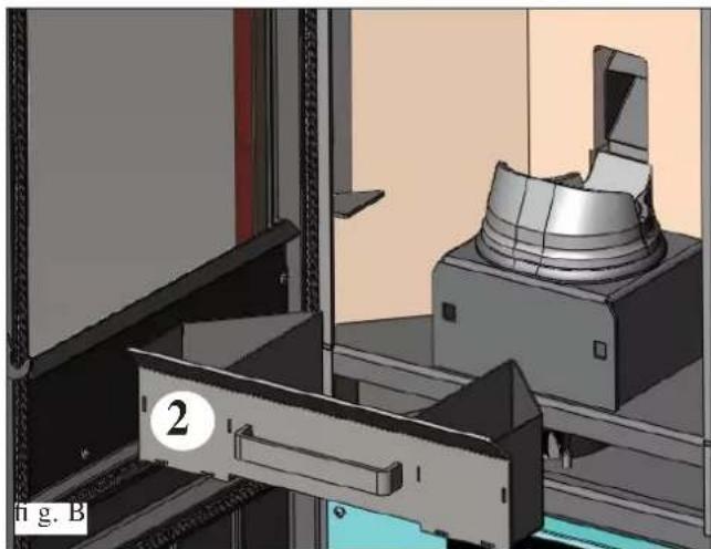
natural_image
3D mechanical assembly diagram showing a clamping mechanism with a labeled component (no text or symbols present)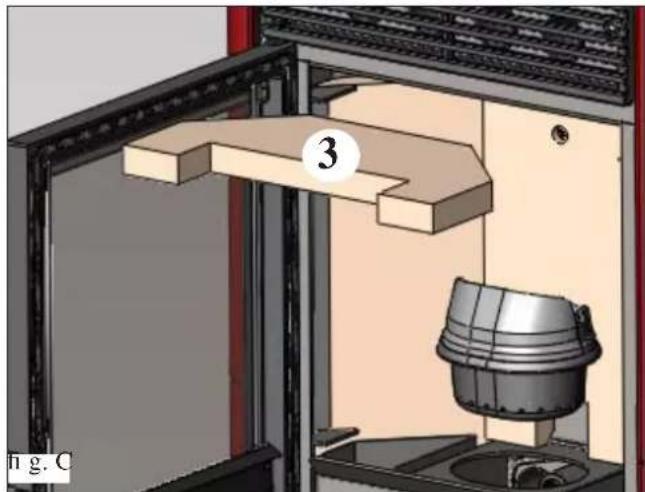
natural_image
3D rendering of a mechanical assembly with a numbered component (3) and a cylindrical housing, no visible text or symbols.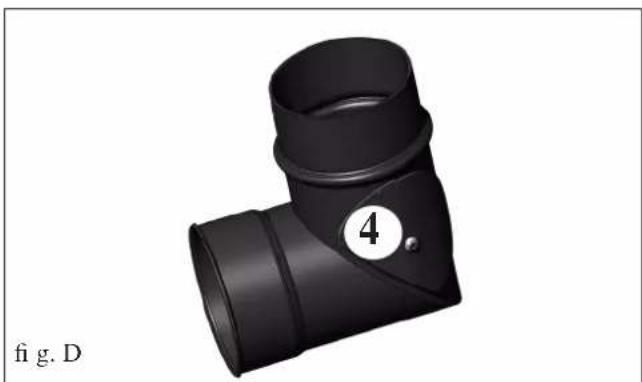
natural_image
3D rendering of a black T-shaped pipe fitting with a numbered circle highlighting part 4 (no text or symbols on the object itself)MANTENIMIENTO
natural_image
3D CAD model of a mechanical assembly with a cylindrical component mounted on a base, shown in 3D perspective (no text or symbols visible)fig.2
CONSEJOS PARA POSIBLES INCONVENIENTES
natural_image
Black and white photo of a vacuum cleaner with attached tubing (no visible text or symbols)Abb. 1
natural_image
Close-up of a mechanical device with a paper sheet and wire, no visible text or symbolsEIGENSCHAFTEN
natural_image
Exterior view of a red and gray portable stove unit (no signage or text visible)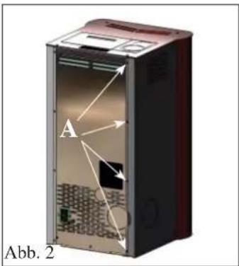
RAUCHABZUG
natural_image
3D cutaway view of a red and black electronic device casing with internal compartments (no text or symbols visible)natural_image
3D diagram of a red and black device with labeled component D, showing internal components and no readable text or symbols.natural_image
3D rendering of a red and black device with labeled component E, shown without any text or symbols on the device itself.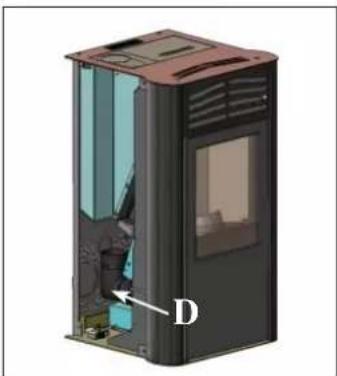
natural_image
3D cutaway view of a small electronic device showing internal components and labeled part D (no text or symbols beyond label)natural_image
3D rendering of a red and black portable stove with ventilation grilles and a chimney (no text or symbols visible)natural_image
Illustration of a red and black industrial oven with ventilation grilles and a lid (no text or symbols)Abb. 1

natural_image
3D rendering of a mechanical device with a labeled component (1) and panel, no readable text or symbols beyond label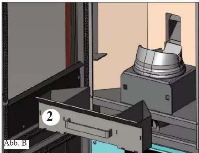
natural_image
3D mechanical assembly diagram showing a rotating component and a bracket (no text or symbols visible)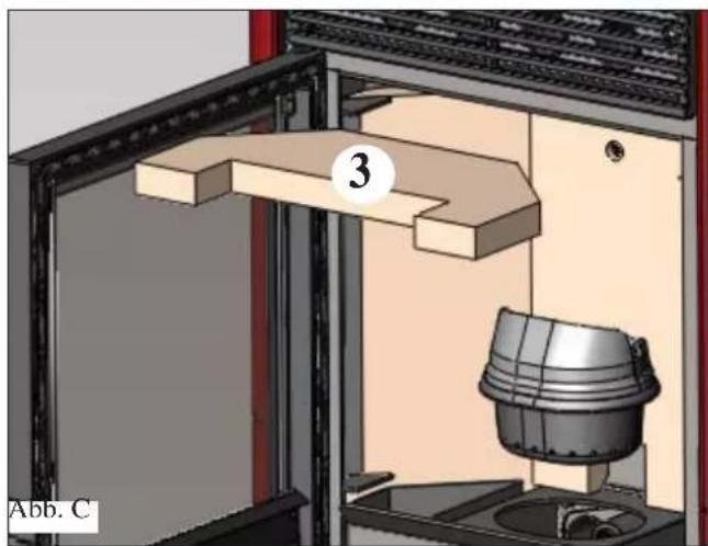
natural_image
3D diagram of a mechanical assembly with labeled component 3, showing internal components and no readable text or symbols.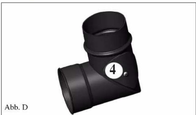
natural_image
Black 3D pipe fitting with a numbered label (4) and Abb. D label, no other text or symbols visible.WARTUNG
JÄHRLICHE WARTUNG
natural_image
3D CAD model of a mechanical assembly with a cylindrical component and mounting bracket (no visible text or symbols)Abb. 2
natural_image
Black and white photo of a vacuum cleaner with attached hose and bulb (no visible text or symbols)fig.1
OPLYSNINGER VEDR∅RENDE SIKKERHEDEN
natural_image
Close-up of a mechanical component with wires and a paper sheet, no visible text or symbolsSPECIFIKATIONER
natural_image
3D rendering of a red and gray portable device with ventilation slots and a labeled arrow pointing to its side (no text or symbols on the device itself)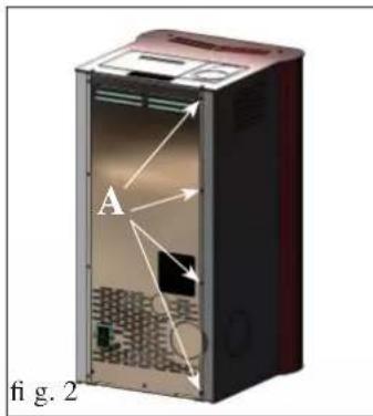
R∅GUDGANG
natural_image
Cutaway illustration of a red and black electronic device casing showing internal components (no text or symbols)natural_image
3D diagram of a red and black device with labeled component D, showing internal components and no readable text or symbols.TILSLUTNING AF R∅GUDGANG I SIDEN
natural_image
3D rendering of a red and black device with labeled component E, shown in figure 8 (no text or symbols on the device itself)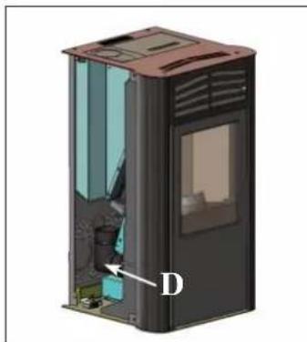
natural_image
3D cutaway view of a device casing with internal components and labeled point D (no text or symbols beyond label)natural_image
3D rendering of a red and black portable air conditioner unit with ventilation grilles and a chimney (no text or symbols visible)NÅR TILSLUTNINGEN AF R∅GUDLEDNINGSR∅RET TIL SKORSTENSR∅RET ER FÆRDIG, SKAL DU GEN- MONTERE METALSIDEN
INSTRUKTIONER FOR BRUG
PÄFYLDNING AF PILLER I BEHOLDEREN
natural_image
Illustration of a red and black industrial air purifier with ventilation slots and a lid (no text or symbols)fig.1

natural_image
Interior view of a laboratory or industrial equipment setup with a container labeled '1' and a lid, no visible text or symbols.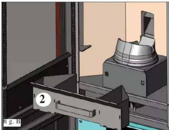
natural_image
3D mechanical assembly diagram showing a clamping device mounted on a metal bracket, with no visible text or symbols.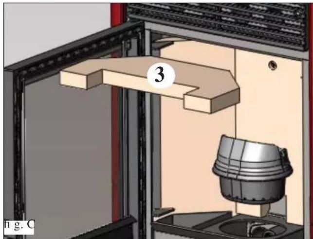
natural_image
3D mechanical assembly diagram showing a door opening, wooden frame, and a bucket with labeled component (no text or symbols beyond label)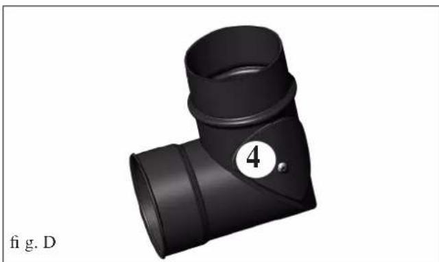
natural_image
3D rendering of a black T-shaped pipe fitting with a numbered circle (4) and label 'fig. D' below (no text or symbols on the object itself)VEDLIGEHOLDELSE
SÆSONVEDLIGEHOLDELSE
natural_image
3D CAD rendering of a mechanical assembly with a cylindrical component mounted on a base, shown in 3D perspective (no text or symbols visible)fig.2
GODE RÅD FOR EVENTUELLE PROBLEMER
natural_image
Black and white photo of a portable vacuum cleaner with attached tubing (no visible text or symbols)Askestøvsuger
natural_image
Close-up of a mechanical device with a paper sheet and wire, no visible text or symbolsEIGENSCHAPPEN
natural_image
3D rendering of a red and black portable stove unit with ventilation grilles and a label 'afb. 1' (no other text or symbols)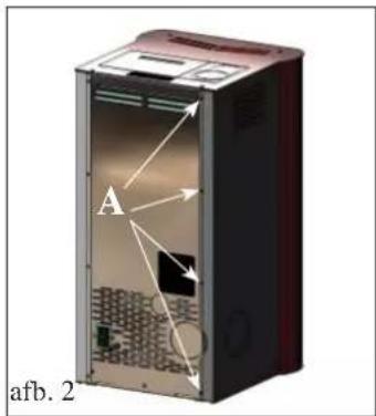
ROOKGASAFVOER
natural_image
3D cutaway view of a red and black electronic device casing with internal compartments and ventilation grilles (no text or symbols)natural_image
3D diagram of a red device with labeled component D, showing internal components and no readable text or symbols.AANSLUITING ZIJDELINGSE ROOKGASAFVOER
natural_image
3D rendering of a red portable air conditioner unit with labeled ports (E) and no visible text or symbols on the device itself.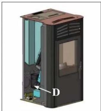
natural_image
3D cutaway view of a device casing with internal components and labeled point D (no text or symbols beyond label)AANSLUITING ROOKGASAFVOER BOVENAAN
natural_image
3D rendering of a red and black portable stove with ventilation grilles and a chimney (no text or symbols visible)NADAT DE ROOKAFVOERBUIS AANGESLOTEN IS OP DE SCHOORSTEEN, MONTEER OPNIEUW HET METALEN ZIJELEMENT.
GEBRUIKSAANWIJZING
natural_image
Illustration of a red and black electronic device with ventilation grilles and a lid (no text or symbols)afb. 1
GEBRUIKSAANWIJZING
SYNOPTISCH PANEEL


natural_image
3D rendering of a mechanical device with a labeled component (1) and panel, no readable text or symbols beyond the label.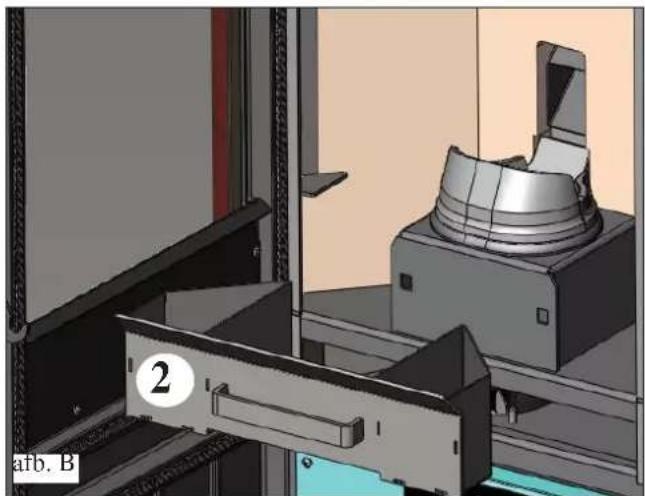
natural_image
3D mechanical assembly diagram showing a rotating component and a bracket (no text or symbols visible)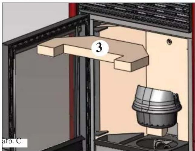
natural_image
3D diagram of a mechanical assembly with labeled component '3' and part identifier 'afb. C' (no readable text or symbols beyond labels)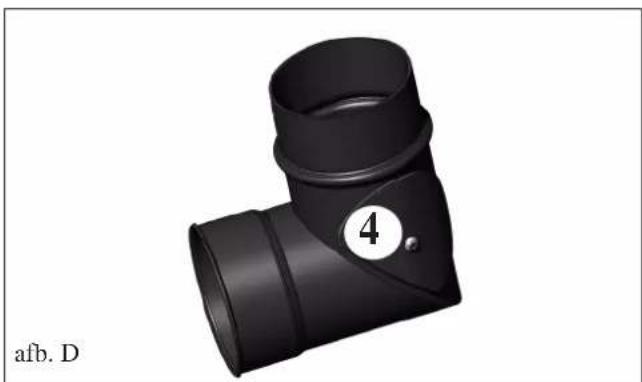
natural_image
3D rendering of a black T-shaped pipe fitting with a numbered circle (4) and label 'afb. D' below (no other text or symbols)ONDERHOUD
SEIZOENSGEBONDEN ONDERHOUD
natural_image
3D CAD model of a mechanical assembly with a cylindrical component mounted on a base, shown in a view from an open frame (no text or symbols visible)afb. 2
ADVIES VOOR MOGELIJKE PROBLEMEN
natural_image
Black Lirgo vacuum cleaner with attached hose and control panel (no visible text or symbols)Aszuiger
fig.1
INFORMAÇÕES DE SEGURANÇA
natural_image
Close-up of a mechanical component with wires and a paper sheet, no visible text or symbolsCARACTERÍSTICAS
natural_image
3D rendering of a red and black portable stove unit with ventilation grilles and a small circular component, labeled 'fi g. 1' (no text or symbols on the device itself)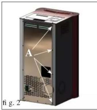
SAÍDA FUMOS
natural_image
3D cutaway diagram of a red and black electronic device casing with internal components (no text or symbols)natural_image
3D rendering of a red and black device with labeled component D, showing internal structure and mounting base (no text or symbols beyond label)natural_image
3D rendering of a red and black portable device with labeled component E, shown in Fig. 7 (no text or symbols on the device itself)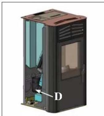
natural_image
3D cutaway view of a device casing with internal compartments and labeled component D (no text or symbols beyond label)natural_image
3D rendering of a red and gray portable stove with ventilation grilles and a chimney (no text or symbols visible)natural_image
Illustration of a red and black electronic device with ventilation grilles and a lid (no text or symbols)fig.1

natural_image
3D rendering of a laboratory apparatus with a container labeled '1' and a side panel, no readable text or symbols beyond the label.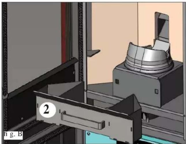
natural_image
3D mechanical assembly diagram showing a clamping device mounted on a bracket, with no visible text or symbols.
natural_image
3D technical diagram of a mechanical assembly with labeled component (no readable text or symbols)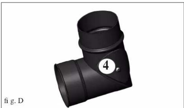
natural_image
3D rendering of a black T-shaped pipe fitting with a numbered circle (4) and label 'fig. D' below (no text or symbols on the object itself)MANUTENÇÃO
MANUTENÇÃO SAZONAL
natural_image
3D CAD model of a mechanical assembly with a cylindrical component mounted on a base, shown in a view from an open frame (no text or symbols visible)fig.2
CONSELHOS PARA POSSÍVEIS INCONVENIENTES
natural_image
Black and white photo of a vacuum cleaner with attached hose and control panel (no visible text or symbols)Balde aspira-cinzas
Thank you for choosing one of our products.
Before using it, we would ask you to carefully read this data sheet, to achieve the best performance and utmost safety when in use.
For further clarifications or requirements, contact the DEALER where you bought the product or visit our website www.edilkamin.com in the section TECHNICAL SUPPORT CENTRES.
NOTE
- Having unpacked the product, ensure the content is intact and complete ("cold hand" handle to open small door, warranty booklet, glove, CD/technical data sheet, spatula, dehumidifying salt).
In the event of anomalies, immediately contact the dealer where you purchased the product, providing him with a copy of the warranty booklet and the receipt.
- Start-up/testing
This must be strictly carried out by an authorised EDILKAMIN Technical Support Centre (TSC), otherwise the warranty is invalid. Start-up, as described by Standard UNI 10683 consists of a series of control operations carried out on the installed and finalised stove to ensure the system is working correctly and it meets the standards in place.
You will find your nearest Technical Support Centre by asking your dealer, on the website www.edilkamin.com or by calling the free phone number.
- improper installation, maintenance incorrectly carried out and improper use of the product relieve the manufacturer of any liability for damages deriving from use.
- the serial number, necessary for stove identifi cation, is indicated:
-on the top of the packaging
- on the warranty booklet available inside the fi rebox
- on the plate applied to the rear of the appliance;
This documentation must be kept for identification together with the receipt whose data should be communicated if you request any information and made available in the event of maintenance intervention.
- the graphically and geometrically represented parts are approximate.
The author EDILKAMIN S.p.A. with its registered office in Via Vincenzo Monti 47 - 20123 Milan - Tax Code/VAT No. 00192220192
Declares under its responsibility that:
The pellet stove outlined below complies with EU Regulation 305/2011 (CPR) and the European Standard EN 14785:2006
PELLET STOVES, under the commercial brand ITALIANA CAMINI, called PRIMA
SERIAL NO. Ref. Data Plate Declaration of Performance (DoP - EK 074): Ref. Data Plate
Also declares that:
the PRIMA wood burning stove complies with the requirements of European Directives:
2006/95/EC- Low Voltage Directive
2004/108/EC- Electromagnetic Compatibility Directive
EDILKAMIN S.p.A. cannot be held in any way liable for the malfunctioning of the appliance in the event of replacement, assembly and/or changes made by staff who do not work for EDILKAMIN without the author's authorisation.
FUNCTIONING PRINCIPLE
The PRIMA stove was designed to produce hot air using wooden pellets as fuel, whose combustion is managed electronically.
Its functioning is illustrated below (the letters refer to Figure 1).
The fuel (pellets) is taken from the storage tank (A) and, using an auger (B) activated by a gearmotor (C), is transported to the combustion crucible (D).
The pellets are ignited using warm air produced by an electrical resistance (E) and sucked into the crucible via the smoke extractor (F).
The smoke produced by combustion is extracted from the fi re-box using the same extractor (F), and expelled from the outlet (G) with the possibility of joining on the rear, on the right/left hand side and on top of the stove (see page 113).
The fi rebox, coated in Vermiculite, is closed on the front with a small, ceramic glass door.
The quantity of combustible, fume extraction and fuel air feed are adjusted by the electronic board equipped with software, to obtain high yield and low emission combustion.
The stove is equipped with a serial socket for connection with an optional cable (code 640560) to remote ignition devices (such as telephone diallers, chronothermostats, etc.).
The outer, steel coating is available in three colour variations: Bordeaux, white and dark grey.
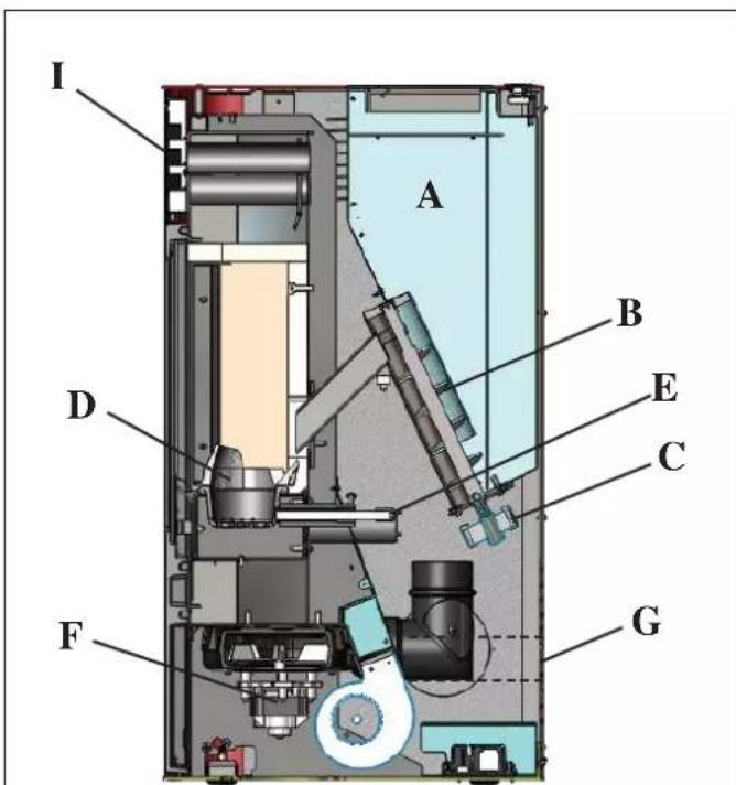
Fig. 1
SAFETY INFORMATION
The hot air is released into the installation environment through a grill (I) located on the top front; the same environment is also radiated by the small, glass door of the fi rebox.
- The appliance is not intended for use by people, including children, whose physical, sensory or mental capacities are reduced. Children must be supervised to ensure they don't play with the appliance.
- The main risks due to stove use can relate to improper installation, direct contact with electrical, powered parts (interior), contact with fire and hot parts (glass, tubes, hot air outlet), the introduction of foreign substances, fuel not recommended, improper maintenance or repeated activation of the ignition key without emptying the crucible.
- In the event of malfunctioning parts or anomalies, the stove is equipped with safety devices to guarantee switch-off, which you should allow to take place without intervention.
- To work properly, the stove must be installed in compliance with the instructions on this data sheet.
- When the stove is on, the door to the fi rebox must not be opened: combustion is in fact automatically managed and does not require any intervention.
- Only use wooden pellets as fuel with a diameter of 6 mm, of optimum quality and certified.
- In no case should foreign substances, other than pellets, be inserted in the fi rebox or the tank.
- Do not use fl ammable products to clean the smoke channel (chimney section connecting the stove smoke outlet to the chimney).
• The parts of the fi rebox and tank must only be vacuumed COLD
- The glass can be cleaned COLD with specific product applied with a cloth (e.g. Glasskamin by Edilkamin).
- Do not clean when hot.
- Ensure the stove is set in place and switched on by a TSC authorised by Edilkamin (Technical Support Centre) according to the instructions in this data sheet; these conditions are however indispensable for warranty validation.
- When the stove is on, the discharge tubing and the door can reach high temperatures (do not touch without the specific glove).
- Do not places objects which are not resistant to heat in the immediate vicinity of the stove.
- NEVER use liquid fuel to light the stove or re-light embers.
- Do not block ventilation openings in the installation premises, nor air inlets to the stove itself.
- Do not wet the stove, do not approach the electrical parts with wet hands.
- Do not insert tube reducers on the smoke vent.
- The stove must be installed in adequate premises to prevent fire and serviced with all utilities (feed and discharge) that the appliance requires for correct and safe operation.
- As is necessary, clean the fl ue pass by removing the Vermiculite firebox and removing the specific brackets.
- IF THE STOVE FAILS TO LIGHT, DO NOT REPEAT IGNITION BEFORE EMPTYING THE CRUCIBLE (IT COULD CAUSE DAMAGE).
- Attention: the pellets emptied from the crucible must not be placed back in the tank.
FRONT
REAR
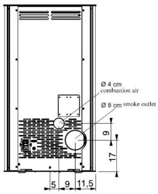
SIDE PLAN
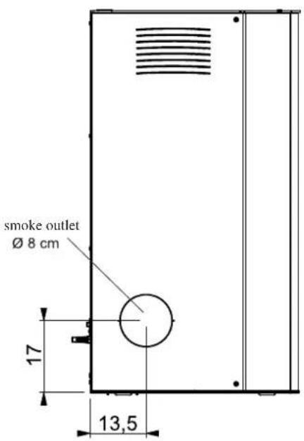
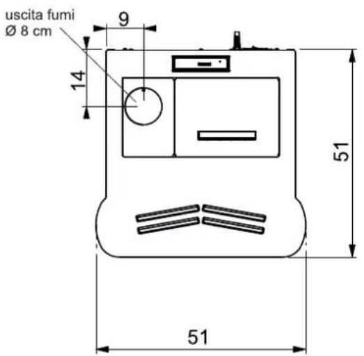
CHARACTERSTICS
SAFETY DEVICES
• THERMOCOUPLE:
On the smoke vent, it detects temperature.
Based on the parameters set, it controls the switch-on, working and switch-off phases.
- PRESSURE SWITCH
On the smoke extraction zone, it intervenes when negative pressure problems are detected on the smoke circuit (e.g.: chimney blocked).
It blocks pellet loading and causes the stove to switch off.
• SAFETY THERMOSTAT:
It activates when the temperature inside the stove is too high. It blocks pellet loading and causes the stove to switch off.
SERIAL PORT
On the serial output RS232 with a specific cable (code 640560) the TSC (Technical Support Centre) can install an optional to control switch-on and switch-off, e.g. ambient thermostat. The serial output is found on the back of the stove.
BUFFER BATTERY
There is a buffer battery on the electronic board (type CR 2032 x 3 Volt).
Its malfunctioning is the result of normal wear (not considered a product fault). For further references, contact the TSC (Technical Support Centre) that carried out first start-up.
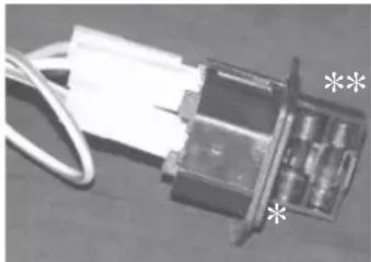
FUSE
on the socket with the switch placed on the rear of the stove, there are two fuses inserted, one of which functional * and the other spare**.
natural_image
Close-up of a mechanical component with wires and a paper sheet, no visible text or symbolsCHARACTERSTICS
| THERMO-TECHNICAL CHARACTERISTICS pursuant to EN 14785 | |||
| Nominal power Reduced power | |||
| Burned heat output 7.8 2.5 kW | |||
| Thermal power 7 2.4 kW | |||
| Yield/Efficiency | 90.1 | 94.67 | % |
| CO emission at 13% O_2 | 0.019 | 0.035 | % |
| Smoke temperature | 174 81 | °C | |
| Fuel consumption | 1.6 0.5 | kg/h | |
| Minimum draft | 12 - 5 | 10 - 3 | Pa |
| Tank capacity | 15 | kg | |
| Autonomy | 8 | 24 | hours |
| Heatable volume * | 180 | m^3 | |
| Smoke pipe diameter (male) | 80 | mm | |
| Air intake pipe diameter (male) | 40 | mm | |
| Weight with packaging | 120 | kg | |
| TECHNICAL DATA FOR CHIMNEY FLUE DIMENSIONING | |||
| Nominal power Reduced power | |||
| Thermal power 7 2.4 kW | |||
| Smoke outlet temperature on discharge | 209 97 | °C | |
| Minimum draft | 0 - 5 | Pa | |
| Smoke capacity | 5.4 2.4 | g/s | |
* The heatable volume is calculated considering home insulation pursuant to L 10/91 and subsequent amendments and a heating requirement of 33Kcal / m^3 per hour.
* It is important to also take into consideration the location of the stove in the environment to heat.
| ELECTRICAL CHARACTERISTICS | ||
| Power supply 230Vac +/- 10% 50 Hz | ||
| Average absorbed power 120 | W | |
| Absorbed power when switching on 400 W | ||
| Protection on electronic board * Fuse F4 AL, 250 Vac | ||
N.B.
1) take into consideration that external equipment can disturb functioning of the electronic board.
2) attention: intervention on the powered parts, maintenance and/or testing must be carried out by qualified staff. (before carrying out any maintenance, disconnect the appliance from the electrical power mains)
The data outlined above are approximate and relate to the certification phase carried out by the notified body. EDILKAMIN s.p.a. reserves the right to change the products without prior notification at its discretion.
As expressly outlined, for each country refer to local standards. In Italy, refer to Standard UNI 10683, as well as any regional or local Health Board specifications. In the event of installation in apartment blocks, ask the administrator's opinion beforehand.
TESTING COMPATIBILITY WITH OTHER APPLIANCES
The stove must NOT be installed in the same premises as type B gas heating appliances (e.g. gas boilers, stoves and equipment with extractor hoods) since this could cause the premises to go into negative pressure and compromise functioning of such equipment or could have an impact on it.
ELECTRICAL CONNECTION TESTING
(position the power socket in an easy to reach point)
The stove is supplied with an electrical power cable to connect to a 230V 50 Hz socket, preferably with a circuit breaker switch.
If the power socket is not easily reached, prepare a power supply switch upstream of the stove (the client is responsible for this).
Changes in voltage over 10% can compromise stove functioning.
The electrical system must be to standard; in particular, check the efficiency of the earthing circuit.
The power line must be adequately sectioned for stove power. An ineffi cient earthing circuit can cause malfunctioning, for which Edilkamin cannot be held liable.
FIRE PREVENTION SAFETY DISTANCES
The stove must be installed in compliance with the following safety conditions:
- minimum distance on the sides and rear 20 cm from fl ammable materials.
- no fl ammable materials must be located in front of the stove for at least 80 cm.
If the aforementioned distances cannot be respected, you need to implement technical and construction measures to avoid the risk of fire. In case of connected with wooden walls or other flammable materials, the smoke vent must be adequately insulated.
AIR INTAKE
It is indispensable for the air intake to be prepared behind the stove connected to the outside, with a minimum useful section of 80 cm^2 , which guarantees sufficient air feed for combustion. In this case, it is NOT possible to position the stove adjacent to a wall.
Alternatively, you can take air for the stove directly from outside using a steel extension with a pipe with a 4 cm diameter or located on the back of the stove itself. The pipe must be less than 1 metre long and not have bends. In any case, the entire pipe path for air intake must have a guaranteed free section of at least 12 cm ^2 . The outer end of the air intake pipe must terminate with a 90° degree section downwards or with a wind-proof protection and be protected with an insect-proof mesh which however doesn't reduce the useful passage section of 12 cm ^2 .
SMOKE VENT
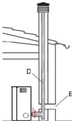
The vent system must be unique for each stove (no discharge is allowed in the chimney fl ue with other devices).
The smoke vent uses an 8 cm diameter outlet on the back, on the right/left hand side or on top.
The smoke vent must be connected with the outside using a steel pipe certified EN 1856.
The pipe must be hermetically sealed.
To seal the pipes and any insulation necessary, use materials resistant to high temperatures (silicone or putty for high temperatures).
The only permitted horizontal section can be up to 2 m long.
You can have a maximum number of 3 bends (max. 90°).
You need (if the vent is not inside a chimney flue) a vertical section of at least 150 cm and a wind-proof end (reference UNI 10683).
If the smoke channel is outside, it must be adequately insulated. If the smoke channel is inserted in a chimney flue, this must be suitable for solid fuel and if over 150 mm, it must be piped with suitably sectioned piping and materials (e.g. 80 mm steel). All the smoke piping sections must inspectionable. The chimney stacks and smoke piping to which the stove is connected must be cleaned at least once a year (check if legislation exists in your country in relation to this).
A lack of regular controls and cleaning increase the probability of fire in the chimney stack; if a fire occurs, do not extinguish with water, empty the pellets tank. Contact specialist staff before starting the machine again. The stove was designed to work in any climatic condition. For particular conditions, such as strong wind, safety systems could activate to switch off the stove. In this case, do not operate the appliance with the safety devices disabled. If the problem persists, contact the Technical Support Centre.
TYPICAL CASES
Fig. 1
Fig.
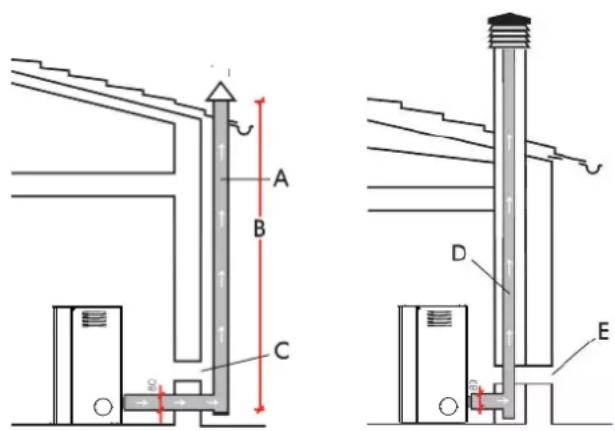
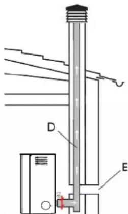
A: chimney fl ue in insulated steel
B: minimum height 1.5 m and however over the eaves on the roof
C-E: air intake from external environment (minimum passage section 80 cm²)
D: chimney flue in steel, inside the existing brick chimney.
CHIMNEY STACK
The fundamental characteristics are:
- internal section at the base equal to the chimney fl ue
- outlet section no less than double that of the chimney fl ue
- position in full wind, over the roof hip and outside the back flow zone
INSTALLATION
natural_image
Illustration of a red and gray portable device with ventilation grilles and a glass door, labeled Fig. 1 (no text or symbols on the device itself)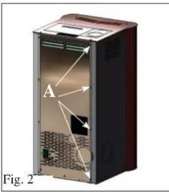
SMOKE OUTLET
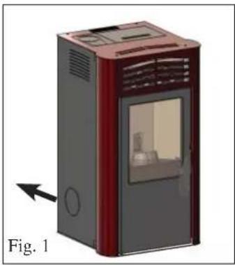
PRIMA is prepared for connection to a smoke outlet pipe from the top, from the back or right or left sides.
The stove is delivered configured for the smoke outlet pipe from the back (Fig. 1).
TO ENABLE ANY CONNECTION SOLUTION OF THE SMOKE OUTLET CONNECTION TO THE CHIMNEY FLUE, YOU NEED TO REMOVE THE RELEVANT METAL SIDE (right or left).
natural_image
3D diagram of a red and gray device labeled 'B' with dimension arrows, shown as Figure 3 (no text or symbols on the device itself)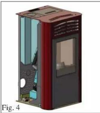
natural_image
3D cutaway illustration of a red and black device casing with internal compartments (no text or symbols)For connections proceed as follows:
- Loosen the four screws on the rear of the side in sheet metal (A - Fig. 2).
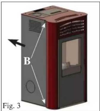
- Remove the two screws from the metal side and remove it (B - Fig. 3).
At this point, choose the connection of the smoke outlet pipe necessary (right or left side).
SMOKE OUTLET CONNECTION FROM REAR
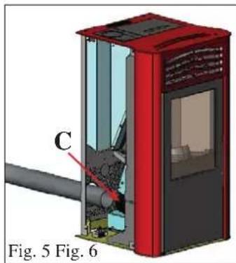
Connect the rear smoke outlet pipe (not supplied) to the smoke outlet spiral (C - Fig. 4-5) using the strip applied.
In this case, simply pass the smoke outlet pipe (not supplied) through the hole on the bottom of the back of the sheet metal (Fig. 5).
natural_image
3D diagram of a red industrial machine with labeled component C, shown in Fig. 5 (no text or symbols on the device itself)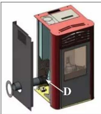
natural_image
3D rendering of a red portable device with labeled component D, showing internal components and no visible text or symbols.Assemble the L shaped joint with the strip (not supplied) on the smoke outlet spiral (D - Fig. 6).
Connect the side smoke outlet pipe (not supplied) to the L shaped joint as above.
Remove the pre-cut diaphragm from the sheet metal side to enable passage of the smoke outlet pipe (not supplied) (Fig. 6).
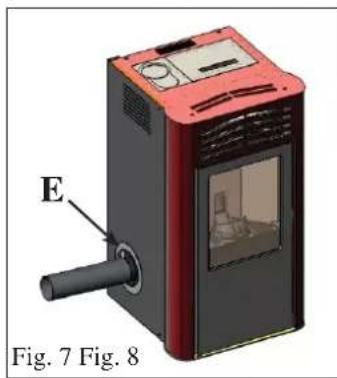
Complete the operation by fastening the closure washer (not supplied E - Fig. 7) using screws, having re-assembled the side in metal.
natural_image
3D rendering of a red and black device with labeled component E, shown in Fig. 7 (no text or symbols on the device itself)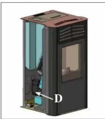
natural_image
3D cutaway view of a device casing with internal components and labeled point D (no text or symbols beyond label)N.B.: fastening the washer and the sheet metal side must take place after definitively fastening the chimney flue.
SMOKE OUTLET CONNECTION FROM TOP
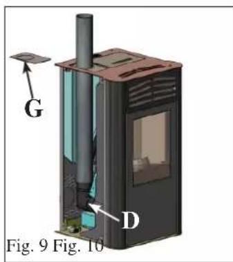
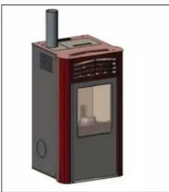
Assemble the L shaped joint with the strip (not supplied) on the smoke outlet spiral (D - fi g. 8).
Connect the smoke outlet pipe (not supplied) to the L shaped joint as above.
Remove the diaphragm from the small semi-cover in sheet metal (G - Fig. 9) to enable pipe passage.
natural_image
3D rendering of a red and gray portable device with ventilation grilles and a small window (no text or symbols visible)Start-up, first switch on and testing must be carried out by an authorised Edilkamin Technical Support Centre (TSC) in compliance with standard UNI 10683.
This standard indicates the control operations to follow to ensure the system is working properly.
The TSC will also calibrate the stove based on the type of pellet and the installation conditions, thereby activating the warranty.
If an authorised TSC does not carry out first switch on the warranty cannot be activated.
For information consult the website www.edilkamin.com
During first switch on, faint odours of paint may develop which will quickly disappear.
Before switching on, you must however check:
==> Correct installation
==> The electrical power supply.
==> Door closure, which must be sealed
==> Crucible cleaning.
==> The presence on the display of the stand-by indication (date, power/temperature flashing).
LOADING PELLETS IN THE TANK
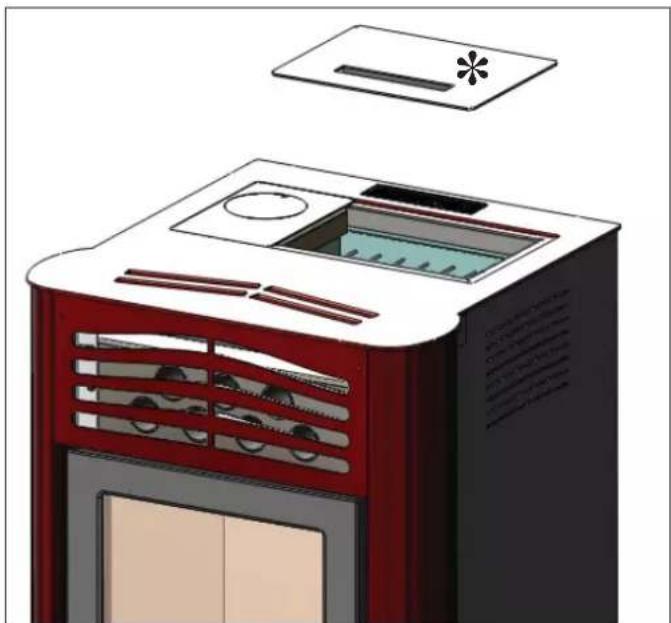
To access the tank, remove the metal cover* (Fig. 1).
ATTENTION:
If you load the stove while it is on, it is therefore hot and the specific glove supplied must be used.
NOTE on fuel.
PRIMA was designed and programmed to burn wooden pellets with an approx. diameter of 6 mm.
Pellets are fuel shaped like small cylinders, obtained by pressing sawdust, at high values, without using glues or other foreign materials.
Pellets are sold in 15 Kg bags.
To AVOID compromising stove operation, do NOT burn anything else.
Use of other materials (including wood), which can be detected through laboratory analysis, would cause the warranty to expire.
EDILKAMIN designed, tested and programmed its products to guarantee the best performance using pellets with the following characteristics:
diameter: 6 millimetres
maximum length: 40 mm
maximum humidity: 8 %
heat yield: 4300 kcal/kg at least
The use of pellets with other characteristics would require specific calibration of the stove, similar to that carried out by the TSC (Technical Support Centre) on first start-up.
The use of unsuitable pellets can cause: reduced performance; functioning anomalies; blockages, dirt on glass, unburned fuel, etc...
A simple analysis of the pellets can be visually carried out:
Good: smooth, regular length, little dust.
Poor quality: with longitudinal and transversal cracks, very dusty, very variable length and the presence of foreign bodies.
natural_image
Illustration of a red and black industrial air purifier with ventilation grilles and a lid (no text or symbols)Fig. 1
INSTRUCTIONS FOR USE
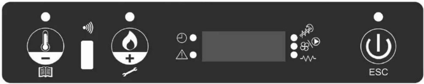
SYNOPTIC PANEL


key to set the ambient temperature desired or to enter the menu (set ambient temp.)

key to set the stove power (set power)

key to switch on/off or confirm exit from menu

indicates the chronothermostat was programmed for automatic and timed switch on

indicates an alarm condition

indicates functioning of the pellet gearmotor

indicates fan functioning

indicates functioning of the glow plug
MENU DESCRIPTION
- To access the menu press the key for 2 seconds (the led switches off).
Pressing the key or the keyboard rolls the following menu:
| M1 | Set clock |
| M2 | Set time programme |
| M3 | Adjust vent 1 |
| M4 | (does not appear at display in this model) |
| M5 | Language |
| M6 | Stand-by |
| M7 | Screw loading |
| M8 | Stove status |
| M9 | Technical calibrations (TAC) |
| MA | Type of pellets (TAC) |
| Mb | Quit |
• To confirm the desired menu press the ⏻ key.
• To go back to the previous menu press the 📄 for 3 seconds.
• To exit the menu press the key for 6 seconds.
SWITCH ON/SWITCH OFF
To switch on/switch off the stove, press the key for 3 seconds.
Led on stove on
Led flashing stove on or in alarm mode
Led off stove off
OPERATION
The stove has two operating modes:
- MANUAL:
In MANUAL operating mode, the power is set on which the stove works, independent of the temperature of the premises in which the stove was installed.
To select MANUAL operating mode,
press the key (the led switches on).
Pressing the key can increase the temperature until the display shows the writing 'MAN' (over 40°).
- AUTOMATIC
In AUTOMATIC operating mode, you can set the objective temperature to obtain in the premises where the stove is installed.
The stove, autonomously, on reaching the desired ambient temperature (SET AMBIENT TEMPERATURE) will set to modulation, going to power 1.
To set the ambient temperature, press (the led switches on), the current working temperature will be displayed,
using the key 5 the key you can change the temperature to reach your desired temperature.
Ventilation is always linked to power in use, therefore it cannot be changed.
INSTRUCTIONS FOR USE
VENTILATION ADJUSTMENT
This function allows you to manage the ventilation speed.
It can be set to AUTO mode, which automatically adjusts the ventilation speed according to the power of the stove, or you can set the ventilation speed according to the amount of hot air or to the desired noise level of the product.
To activate the function, press the 🔒 key for 2 seconds and press the 🔒 y until the display shows the message “M3 Adjust vent 1”.
Press the 🤒️ and set the desired ventilation speed using the keys an 🤒️
To confirm your choice, press the key.
AUGER LOADING (only in the event the stove is completely without pellets)
To load the auger enter the MENU, press the 🔊 key for 2 seconds, press the 🔊 key until the writing on the display “M5 first load” appears.
Press the ECG key to confirm and then press the key to activate the function. This operation must only be carried out with the stove off and completely cold.
Note: during this phase the smoke extractor will stay on.
STAND-BY FUNCTION
This function, managed automatically, allows the stove to be switched off on surpassing 0.5 ^ of the ambient temperature required, after a preset time of 10 minutes (which can be modified by the TSC during the installation phase).
On the display the writing "GO STBY" appears indicating the remaining minutes to switch off.
This function is present in 'AUTOMATIC' functioning and in the event of an external thermostat.
If the ambient temperature lowers by 2^ under the threshold set, the stove re-starts (this can be modified by the TSC during the installation phase).
To activate the function, press the 🔊 key for around 3 seconds, the writing “M1 set clock” will appear on the display, press the key until you see the writing “M4 stand by” on the display, to confirm press the 🔊 key.
Press the key to select "ON", to confirm press the key
To exit the “M4 stand by” menu, press the 🤊️ for approx. 6 seconds.
TIME AND DATE ADJUSTMENT
Press the 🔒 key for around 2 seconds, the writing “M1 set clock”, will appear, to confirm press the 🔒 key. The following data appear in sequence. Day of the week, hour, minutes, day, month and year
which can be changed, press the 🔊 key or ⚠️ key. To confirm press the ⏻ key.
To exit the “M1 set clock” menu, press the ⏻ y for approx. 6 seconds.
EXTERNAL THERMOSTAT
It must be connected via the blue wire (optional code 640560) to the serial port positioned on the rear of the stove. There must be clean, normally open contact (e.g. for an ambient thermostat):
- Contact open = Ambient temperature reached - Contact closed = Ambient temperature not reached
To select ‘T-E’ (external thermostat) mode, press the key (the led switches on). Press the key to decrease the temperature until the writing ‘T-E’ (external thermostat) appears on the display (under 6°).
Note: With the stove off, the external thermostat cannot in any case switch on or off the stove. If you want to switch off or on the stove outside the chrono time or the 'T-E' (external thermostat) setting, you always need to use the ⏻ key.
INSTRUCTIONS FOR USE
CHRONOTHERMOSTAT FOR DAILY/WEEKLY PROGRAMMING
Three programming modes are planned (daily, weekly and weekend), each of which is independent from the other and thereby allows multiple combinations according to personal requirements (you can adjust the hours in 10 minute steps).
Press the key for 2 seconds. The writing “M1 set clock” appears on the display (the led switches on).
Press the 🔒 key until the writing “M2 set chrono” appears on the display, to confirm press the 🔒 key.
To display the 3 programming modes (daily, weekly, weekend) press the 🔒 key or the 🔒 key. To confirm press the 🔒 key.
Scroll the following menu (by default it is set to OFF):
- M2-1: enable chronothermostat
- M2-2: day program
- M2-3: weekend program
- M2-4: weekend program
- M2-5: exit
Choose the desired menu and confirm by pressing the
To set the stove switch on and switch off and vary the times press the 🔒 key or the 🔒 key, to confirm press the 🔒 key.
To exit programming, press the 🧑️ for approx. 6 seconds.
Daily programming
possibility of 2 switch ons/switch offs during the day repeated for all days:
Example: start1 10:00
stop1 12:00
start2 18:00
stop2 22:00
Weekly Programming:
possibility of 4 switch ons/switch offs during the days chosen for the week, example:
| start1 06:00 stop1 08:00 start2 07:00 stop2 10:00 start3 14:00 stop3 17:00 start4 19:00 stop3 22:00 | |||
| Monday onTuesday onWednesday offThursday onFriday onSaturdayoffSunday off | Monday offTuesday offWednesday onThursday offFriday offSaturdayoffSunday off | Monday onTuesday onWednesday offThursday offFriday offSaturdayonSunday on | Monday onTuesday onWednesday onThursday onFriday onSaturdayonSunday on |
Weekend Programming:
possibility of 2 switch ons/switch offs during the weekend:
Example: start1 weekend 07:00 stop1 weekend 11:30
Example: start2 weekend 14:20 stop2 weekend 23:50
MAINTENANCE
Before carrying out any maintenance, disconnect the appliance from the electrical power mains.
Regular maintenance is based on good stove operation.
LACK OF MAINTENANCE CANNOT allow the stove to work properly.
Any problems due to lack of maintenance will cause the warranty to expire.
N.B.:
- Changes made by unauthorised staff are forbidden
- Use spare parts recommended by the manufacturer
- Use of non-original spare parts causes the warranty to expire
DAILY MAINTENANCE
Operations to carry out, with the stove off, cold and disconnected from the electrical mains.
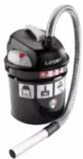
- It must be carried out with the help of a vacuum cleaner (see optionals on page 121).
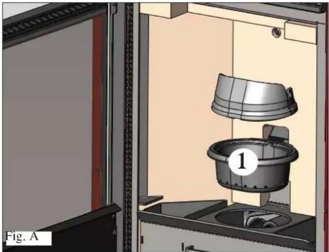
• The entire procedure takes a few minutes. - Open the small door, remove the crucible (1 - Fig. A) and tip the residue in the ash drawer (2 - Fig. B).
- DO NOT RELEASE CLEANING RESIDUE INTO THE PELLET TANK.
- Extract and empty the ash drawer (2 - Fig. B) into a container which cannot catch fire (the ash can contain parts that are still hot and/or embers).
• Vacuum inside the firebox, the fire surface, the chamber around the crucible and where the ash falls. - Remove the crucible (1 -Fig. A) and de-scale with the small brushes supplied, clean any blockages from the holes.
• Vacuum the crucible chamber, clean around the edges of the crucible in contact with its compartment. - If necessary, clean the glass (when cold)
Never vacuum hot ash as it would compromise the vacuum cleaner used and could cause a fire in the home
WEEKLY MAINTENANCE
- Remove the ceiling (3 - Fig. C) and tip the residue in the ash drawer (2 - Fig. B). The ceiling is a component subject to wear. Edilkamin cannot be held liable for its breakage, even more so if breakage is due to its removal or re-positioning in its compartment.
MONTHLY MAINTENANCE
If the smoke outlet is connected on top (see page 8) clean inside the L shaped joint removing it for inspection (4 - Fig. D).
natural_image
3D rendering of a mechanical device with a bucket and housing, labeled 'Fig. A' (no text or symbols on the diagram itself)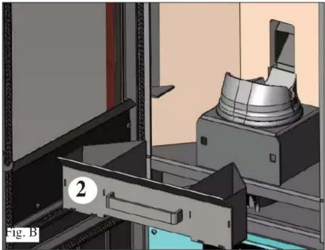
natural_image
3D mechanical assembly diagram showing a component being processed into a machine (no visible text or symbols)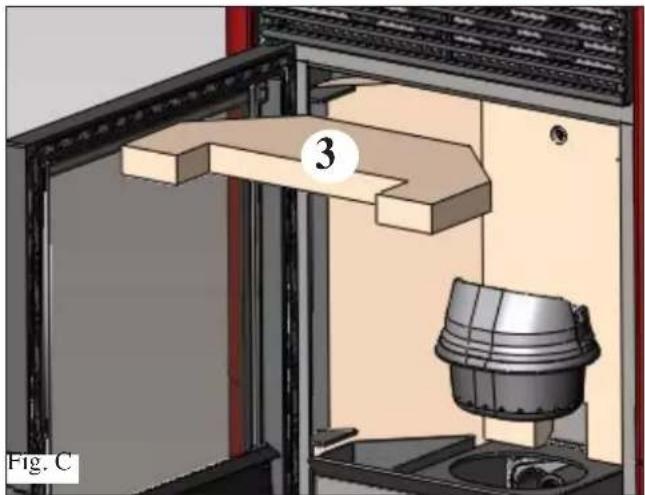
natural_image
3D diagram of a mechanical assembly with labeled component (3), no readable text or symbols present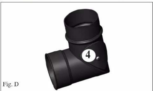
natural_image
3D rendering of a black T-shaped pipe fitting with a numbered circle (4) on one end, labeled Fig. D (no text or symbols on the object itself)MAINTENANCE
(implemented by the TSC - Technical Support Centre) It consists of:
- Cleaning the stove internally and externally
- Thorough cleaning of the horizontal exchange piping inside the hot air outlet grill located in the upper part of the front of the stove
- Carefully cleaning and removing dirt from the combustion chamber and the relative compartment
• Emptying the pellet tank and vacuuming the bottom. - Cleaning the smoke extractor and mechanically checking the ranges and fastenings
- Cleaning the smoke channel (replace seals on smoke vent pipe)
- Cleaning the smoke pipe and vertical exchange piping behind the walls inside the fi rebox
- Cleaning the smoke extractor fan chamber, cleaning the pressure switch, - Checking the thermocouple.
- Cleaning, inspecting and de-scaling the ignition resistance chamber, replace if necessary
- Cleaning/checking the synoptic panel
- Visual inspection of the electrical cables, the connections and power supply cable
- Cleaning the pellet tank and checking the auger-gearmotor assembly ranges
- Checking and replacing, if necessary, the small pressure switch tube
- Replacing the door seal
- Functional testing: auger loading, switch on, operation for 10 minutes and switch off
In the event of very frequent stove use, you are advised to clean the smoke passage pipe and channel every 3 months.
ATTENTION !!!
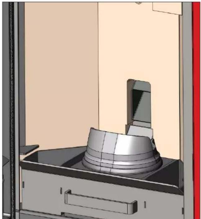
After normal cleaning, INCORRECT coupling of the upper crucible (A) (Fig. 1) with the lower crucible (B) (Fig. 1) can compromise stove operation.
Then before switching on the stove, ensure the crucibles are correctly coupled as indicated in (Fig. 2) without the presence of ash or fuel on the contact perimeter.
Remember that using the stove, without cleaning the crucible, could cause sudden ignition of the gases inside the combustion chamber and result in breakage of the glass on the door.
N.B.:
The chimney stacks and smoke piping to which solid fuel using appliances are connected must be cleaned once a year (check if legislation exists in your country in relation to this).
Lack of regular controls and cleaning will increase the probability of a fi re in the chimney stack.
IMPORTANT !!!
If a fi re starts in the stove, in the smoke channel or in the chimney, proceed as follows:
- Disconnect electrical power
- Use a carbon dioxide CO_2 extinguisher - Request the intervention of the Fire Brigade
DO NOT ATTEMPT TO EXTINGUISH THE FIRE WITH WATER!
Subsequently, ask an Authorised Edilkamin Technical Support Centre to check the appliance and have an authorised technician check the chimney.
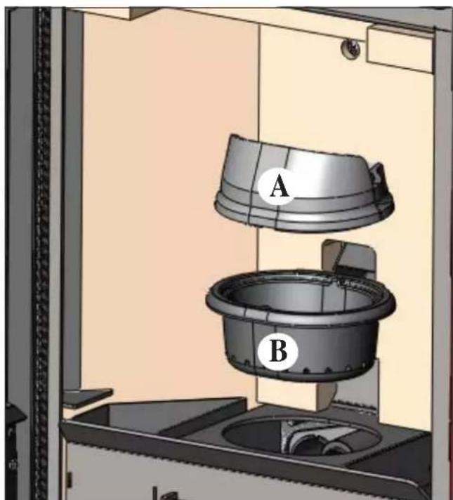
Fig. 1
natural_image
3D rendering of a mechanical assembly with a cylindrical component mounted on a base, shown in a technical view (no text or symbols visible)Fig. 2
POSSIBLE TROUBLESHOOTING
In the event of problems the stove stops automatically and runs the shutdown process and the display shows text regarding the motivation for the shutdown (see the various alarms below).
Never pull the plug during shutdown on account of malfunctioning.
Should it block, to re-start the stove you will need to allow the switch off procedure to take place (15 minutes
with an audible signal) and then press the 📄 key.
Do not turn the stove on again before checking the cause of the malfunction and CLEANING/ EMPTYING the crucible.
INDICATION OF POSSIBLE CAUSES OF MALFUNCTION INSTRUCTIONS AND SOLUTIONS:
AL1 black out (not a stove fault) (this occurs in the absence of a electrical power voltage over 5 seconds)
The stove has a ‘black out’ function. If there is an electrical power cut, for a time of less than 5 seconds, the stove will switch back on and return to operating pre-black out.
If the time is greater, the stove will position in the black out alarm mode, resulting in the cooling phase.
A list of the various possibilities follow:
| Stove status before black out Deactivation time under 10" Deactivation time over 10" | ||
| OFF OFF OFF | ||
| PRE-LOAD BLACK OUT BLACK OUT | ||
| SWITCH ON BLACK OUT BLACK OUT | ||
| START START RE-SWITCH ON STAND-BY | ||
| WORK WORK RE-SWITCH ON STAND-BY | ||
| FINAL CLEANING FINAL CLEANING FINAL CLEANING | ||
| STAND-BY | STAND-BY | STAND-BY |
| ALARM | ALARM | ALARM |
| ALARM MEMORY | ALARM MEMORY | ALARM MEMORY |
AL2 broken smoke probe (this occurs when the stove can no longer read the probe)
• Thermocouple broken
• Thermocouple disconnected
- Smoke temperature out of measurement range
AL3 hot smoke (this occurs when the smoke temperature exceeds a safe temperature)
- Blocked chimney fl ue
- Improper installation
- Stove blocked
• High pellet loading, check pellet regulation (TSC)
NOTE: the "hot smoke" message appears having surpassed the FIRST threshold alarm of 250^ sending the stove in modulation, only on reaching 270^ will the stove go to alarm mode and switch off.
AL4 suction fault (occurs when the smoke motor is faulty)
- Smoke motor blocked
- Rotation sensor faulty
- Smoke motor faulty
- Smoke motor thermostat activation
AL5 no switch on (this occurs during the switch on phase when the smoke temperature does not exceed the minimum threshold)
• Probable glow plug fault
- Crucible dirty or too many pellets
Pellets are used up
- Check the pellet safety thermostat (automatic resetting)
- Blocked chimney fl ue
AL6 no pellets (this occurs when the pellets are used up)
- No pellets in tank
- Gearmotor faulty
- Pellet duct/auger blocked
- Low pellet loading, check pellet adjustment
AL7 thermal safety switch (this occurs when the safety thermostat, in contact with the tank, trips due to excess temperature in the pellet tank)
- Excess pellet loading
AL8 no negative pressure (this occurs where the draft is insufficient in the cold air suction tube)
• Cold air tube blocked
- Pressure switch faulty
• Clogged silicone tube
CHECK LIST
To integrate with complete reading of the technical data sheet
Laying and installation
- Start-up carried out by the authorised TSC that issued the warranty
• Premises ventilation
• The smoke channel/chimney fl ue only receives stove discharge
• The smoke channel has: a maximum 3 bends a maximum 2 metres horizontally
• crucible beyond the back flow zone - the exhaust piping is not in suitable material (stainless steel recommended)
- in crossing any fl ammable materials (e.g. wood) all the precautions were taken to avoid fi res
Use
• The pellets used are good quality and not damp
• The crucible and the ash chamber are clean and well positioned
• The door is closed properly
• The crucible is well inserted in the specific chamber
REMEMBER TO VACUUM THE CRUCIBLE BEFORE EACH SWITCH ON In the event the stove fails to light, do NOT repeat switch on BEFORE emptying the crucible.
OPTIONALS
• REMOTE CONTROL
- MULTIPLE SMOKE OUTLET KIT (washer, L shaped joint, stainless steel strip ∅ 84)
CLEANING ACCESSORIES
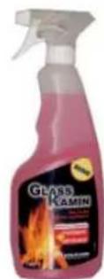
GlassKamin
Useful to clean ceramic glass
natural_image
Black industrial vacuum cleaner with attached hose and control panel (no visible text or symbols)Ash vacuum cleaner
Useful to clean the fi rebox

- INFORMAZIONI PER LA SICUREZZA
- CARATTERISTICHE
- USCITA FUMI
- COLLEGAMENTO USCITA FUMI LATERALE
- COLLEGAMENTO USCITA FUMI DAL TOP
- UNA VOLTA TERMITA L'OPERAZIONE DI COLLEGAMENTO DEL TUBO USCITA FUMI ALLA CANNA FUMARIA RIMONTARE IL FIANCO IN METALLO.
- ISTRUZIONI D'USO
- PANNELLO SINOTTICO
- MANUTENZIONE
- CONSIGLI PER POSSIBILI INCONVENIENTI
- INFORMATIONS POUR LA SÉCURITÉ
- CARACTÉRISTIQUES
- SORTIE DES FUMÉES
- RACCORDEMENT SORTIE FUMÉES LATÉRALE
- UNE FOIS L'OPÉRATION DE RACCORDEMENT DU TUYAU DE SORTIE DES FUMÉES AU CONDUIT DE CHEMINÉE TERMINÉE, REMONTER LE CÔTÉ EN MÉTAL.
- MODE D'EMPLOI
- CHRONOTHERMOSTAT A PROGRAMMATION JOURNALIÈRE/HEBDOMADAIRE
- ENTRETIEN
- ENTRETIEN SAISONNIER
- CONSEILS EN CAS D'ÉVENTUELS INCONVÉNIENTS
- CARACTERÍSTICAS
- SALIDA DE HUMOS
- INSTRUCCIONES DE USO
- PANEL SINÓPTICO
- MANTENIMIENTO
- CONSEJOS PARA POSIBLES INCONVENIENTES
- EIGENSCHAFTEN
- RAUCHABZUG
- WARTUNG
- JÄHRLICHE WARTUNG
- OPLYSNINGER VEDR∅RENDE SIKKERHEDEN
- SPECIFIKATIONER
- R∅GUDGANG
- TILSLUTNING AF R∅GUDGANG I SIDEN
- INSTRUKTIONER FOR BRUG
- PÄFYLDNING AF PILLER I BEHOLDEREN
- VEDLIGEHOLDELSE
- SÆSONVEDLIGEHOLDELSE
- GODE RÅD FOR EVENTUELLE PROBLEMER
- EIGENSCHAPPEN
- ROOKGASAFVOER
- AANSLUITING ZIJDELINGSE ROOKGASAFVOER
- AANSLUITING ROOKGASAFVOER BOVENAAN
- GEBRUIKSAANWIJZING
- SYNOPTISCH PANEEL
- ONDERHOUD
- SEIZOENSGEBONDEN ONDERHOUD
- ADVIES VOOR MOGELIJKE PROBLEMEN
- INFORMAÇÕES DE SEGURANÇA
- SAÍDA FUMOS
- MANUTENÇÃO
- MANUTENÇÃO SAZONAL
- CONSELHOS PARA POSSÍVEIS INCONVENIENTES
- FUNCTIONING PRINCIPLE
- SAFETY INFORMATION
- CHARACTERSTICS
- SAFETY DEVICES
- • THERMOCOUPLE:
- - PRESSURE SWITCH
- • SAFETY THERMOSTAT:
- SERIAL PORT
- BUFFER BATTERY
- FUSE
- N.B.
- TESTING COMPATIBILITY WITH OTHER APPLIANCES
- ELECTRICAL CONNECTION TESTING
- (position the power socket in an easy to reach point)
- FIRE PREVENTION SAFETY DISTANCES
- AIR INTAKE
- SMOKE VENT
- CHIMNEY STACK
- INSTALLATION
- SMOKE OUTLET
- TO ENABLE ANY CONNECTION SOLUTION OF THE SMOKE OUTLET CONNECTION TO THE CHIMNEY FLUE, YOU NEED TO REMOVE THE RELEVANT METAL SIDE (right or left).
- SMOKE OUTLET CONNECTION FROM REAR
- SMOKE OUTLET CONNECTION FROM TOP
- LOADING PELLETS IN THE TANK
- ATTENTION:
- NOTE on fuel.
- diameter: 6 millimetres
- maximum length: 40 mm
- maximum humidity: 8 %
- heat yield: 4300 kcal/kg at least
- INSTRUCTIONS FOR USE
- SYNOPTIC PANEL
- MENU DESCRIPTION
- SWITCH ON/SWITCH OFF
- OPERATION
- - MANUAL:
- - AUTOMATIC
- VENTILATION ADJUSTMENT
- AUGER LOADING (only in the event the stove is completely without pellets)
- STAND-BY FUNCTION
- TIME AND DATE ADJUSTMENT
- EXTERNAL THERMOSTAT
- CHRONOTHERMOSTAT FOR DAILY/WEEKLY PROGRAMMING
- Daily programming
- Weekly Programming:
- Weekend Programming:
- MAINTENANCE
- N.B.:
- DAILY MAINTENANCE
- WEEKLY MAINTENANCE
- MONTHLY MAINTENANCE
- ATTENTION !!!
- POSSIBLE TROUBLESHOOTING
- INDICATION OF POSSIBLE CAUSES OF MALFUNCTION INSTRUCTIONS AND SOLUTIONS:
- CHECK LIST
- To integrate with complete reading of the technical data sheet
- Laying and installation
- Use
- OPTIONALS
- CLEANING ACCESSORIES
Brand : EDILKAMIN
Model : PRIMA
Category : Frying Pan