
Klima - Pan EDILKAMIN - Free user manual and instructions
Find the device manual for free Klima EDILKAMIN in PDF.
| Product type | Wood-burning thermostove |
| Brand | Edilkamin |
| Model | Klima |
| Fuel | Dry natural wood (humidity <20%) |
| Useful power | 19.7 kW |
| Power delivered to water | 11.6 kW |
| Power delivered to environment | 8.1 kW |
| Overall efficiency | 80.7% |
| Flue gas temperature | 225 °C |
| Water content | 40 L |
| Maximum wood consumption | 5.5 kg/h |
| Minimum draft | 12 Pa |
| Maximum operating pressure | 1.5 bar |
| Weight (base, packaging included) | 275 kg |
| Flue outlet diameter | 15 cm |
| Indicative heating volume | 515 m³ |
| Electrical supply (controller) | 230 Vac, 50/60 Hz |
| Firebox material | Thick steel |
| Door material | Cast iron with ceramic glass |
| Exterior cladding | Ceramic |
| Installation type | Open or closed expansion tank (CS version) |
| Main functions | Central heating and domestic hot water production (with kits) |
| Regulation | Electronic with thermostat, 3-way valve, pump |
| Routine maintenance | Cleaning the glass when cold, ash vacuuming |
| Safety | Thermal relief valve, overheat alarm, automatic shutdown |
Frequently Asked Questions - Klima EDILKAMIN
User questions about Klima EDILKAMIN
0 question about this device. Answer the ones you know or ask your own.
Ask a new question about this device
Download the instructions for your Pan in PDF format for free! Find your manual Klima - EDILKAMIN and take your electronic device back in hand. On this page are published all the documents necessary for the use of your device. Klima by EDILKAMIN.
USER MANUAL Klima EDILKAMIN
UK Installation, use and maintenance pag. 25
F Installation, usage et maintenance pag. 48
TERMOSTUFE A LEGNA, a marchio commerciale EDILKAMIN, denominate KLIMA - WARM e KLIMA/CS - WARM/CS
Per WARM / KLIMA BASE:
- 4 elementi laterali (1)
-2 elementi anteriore (2)
-1top(3)
SET CERAMICHE WARM / KLIMA con scaldavivande
thank you for choosing our KLIMA and WARM boiler-stoves
Before using your boiler-stove, please read this booklet carefully: it explains how to exploit all its features to the full in complete safety.
Please remember that installation MUST be carried out by qualified staff authorized according to Italian law 46/90.
Every country must refer to its own national regulations. If you require, EDILKAMIN can provide trained staff in every region in Italy (website www.edilkamin.com, under "technical assistance centres").
The manufacturer cannot be held liable for any damage deriving from boiler-stove use following incorrect installation, incorrect maintenance or misuse.
SAFETY INFORMATION:
THE BOILER-STOVE MUST NEVER BE RUN WITHOUT WATER IN THE SYSTEM.
"WATERLESS" IGNITION DAMAGES THE BOILER-STOVE.
- The boiler-stove is designed to heat water through the automatic combustion of wood in a firebox.
The only risks which may derive from using the boiler-stove are linked with noncompliance with the installation instructions, direct contact with live electrical parts (outside) or with the fire or hot parts, and the introduction of foreign substances. - Do not use flammable products to clean the smoke duct.
- Firebox components must only be cleaned WHEN COLD using a vacuum cleaner.
The glass must be cleaned when COLD with a special cleaner (e.g. GlassKamin) and cloth. Do not clean when hot. - During boiler-stove operation, the outlet pipes and door reach high temperatures.
- Do not keep objects which are not able to withstand heat in the immediate vicinity of the boiler-stove.
- NEVER use liquid fuels to light the boiler-stove or rekindle the embers.
- Do not block ventilation openings in the room where the boiler-stove is installed or air inlets in the boiler-stove itself.
- Do not get the boiler-stove wet, and do not put wet hands near electrical parts.
- Do not fit reducers on the smoke outlet pipes.
- The boiler-stove must be installed in a suitable place as regards fire regulations, and provided with all the facilities (power supply and outlet) it requires for correct operation.
Declaration of conformity
The undersigned EDILKAMIN S.p.a. with head office headquarters at Via Vincenzo Monti 47 - 20123 Milan - Italy - VAT IT00192220192
Declares under its own responsibility as follows:
The boiler-stoves specified below is in accordance with the 89/106/EEC (Construction Products)
THE BOILER-STOVES, trademark EDILKAMIN, called KLIMA - WARM e KLIMA/CS - WARM/CS
YEAR OF MANUFACTURE: Ref. Data nameplate
SERIAL NUMBER: Ref. Data nameplate
The compliance with the 89/106/EEC directive is besides determined by the compliance with the European standard:
KLIMA - WARM UNI EN 13240:2006
KLIMA/CS - WARM/CS UNI EN 13240:2006
Also declares as follows:
The boiler-stoves KLIMA - WARM e KLIMA/CS - WARM/CS is in compliance with the requirements of the European directives:
2006/95/EEC - Low voltage directive
2004/108/EEC - Electromagnetic compatibility directive
EDILKAMIN S.p.a. will decline all responsibility of malfunctioning or damage to the equipment in case of unauthorized substitution, assembly or modifications of any sort on the sold equipment on the part of non-EDILKAMIN S.p.a. personnel.
All models are available:
installation in an open expansion
or
version CS, with built-in coil operated by a heat discharge valve, for installation with closed expansion.
NOTES on fuel:
The KLIMA and WARM boiler-stoves are designed to burn wood.
In order NOT to jeopardize boiler-stove operation, do NOT burn other substances.
The calorific value of wood varies considerably according to its moisture content. The declared boiler-stove power output in kW may be obtained by burning the recommended quantity of wood, being careful not to overload the combustion chamber.
OPERATING PRINCIPLE/TECHNICAL DATA
The boiler-stove is designed to heat the room it is installed in by convection, radiation and the water found in it, which is sent to heat radiators and/or to the domestic hot water system (according to the type of system). The heat is generated by burning wood in the thick steel firebox.
The smoke leaves through the flue with natural draught.
Ash falls into the pan where it gathers for emptying.
Optimum performance is also obtained thanks to the following features:
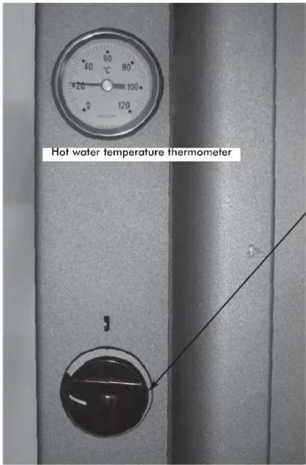
PRIMARY AIR REGULATION (for combustion)
Combustion air intake is automatically regulated by the control valve found on the back of the boiler-stove according to:
-
the position of the knob
-
the water temperature
AUTOMATIC SMOKE BY-PASS VALVE
During the ignition stage with the door open, the smoke shutter stays in an open position so that the smoke can reach the flue directly and easily to help combustion begin.
When combustion is well under way, closing the door also automatically closes the smoke shutter.
In this situation, the smoke is diverted before reaching the flue so that it flows against and transfers heat to the hollow jackets and heat exchanger tubes.
SECONDARY AIR REGULATION
The fixed secondary air flow goes directly to the firebox through the slits in the upper part of the firebox door. As well as allowing the ceramic glass to clean itself, it helps burn any gases which may be given off by incomplete wood combustion, thus reducing dangerous gas emissions into the environment.
AUTOMATIC DOOR CLOSURE
The firebox door (made of cast iron with high temperature resistant ceramic glass) allows a panoramic view of the fire and closes automatically with a spring return for optimum combustion.
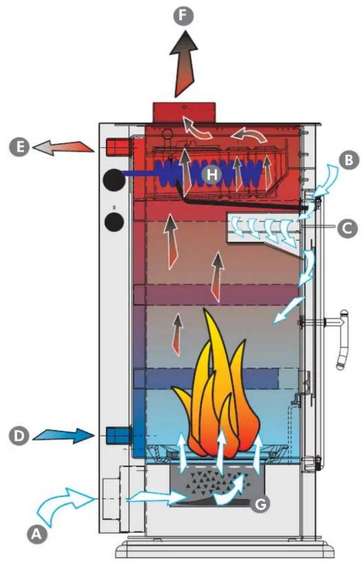

Primary air inlet

Secondary air inlet

Secondary air regulation lever

Cold water inlet

Hot water outlet

Smoke outlet

Ashpan

Coil
| TECHNICAL AND HEATING SPECIFICATIONS | |||
| Klima/Warm Klima CS/Warm CS | |||
| Available power 19,7 14 kW | |||
| Power output for water 11,6 10 kW | |||
| Power output to room 8,1 4 kW | |||
| Overall efficiency 80,7 81,6 % | |||
| Smoke temperature 225 234 °C | |||
| Smoke flow 18,2 11,3 g/s | |||
| Water content | 40 | 40 | 1 |
| Fuel consumption max | 5,5 4 kg/h | ||
| Minimum draught | 12 | 12 | Pa |
| Maximum pressure | 1,5 | 1,5 | bar |
| Klima weight (basic/hotplate) including the packaging | 275/305 | 278/308 | kg |
| Warm weight (basic/hotplate) including the packaging | 250/274 | 253/276 | kg |
| Smoke outlet diameter | 15 | 15 | cm |
| Heating capacity * | 515 | 365 | m³ |
- The heatable room dimensions are calculated assuming the use of wood of the type described in the note, and home insulation which complies with Italian law No. 10/91, and subsequent changes together with an expected heat output of 33 Kcal/m³ hour.
ENGLISH
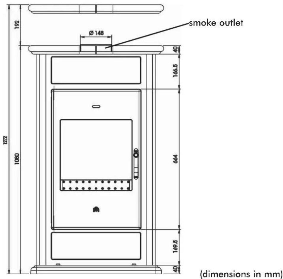
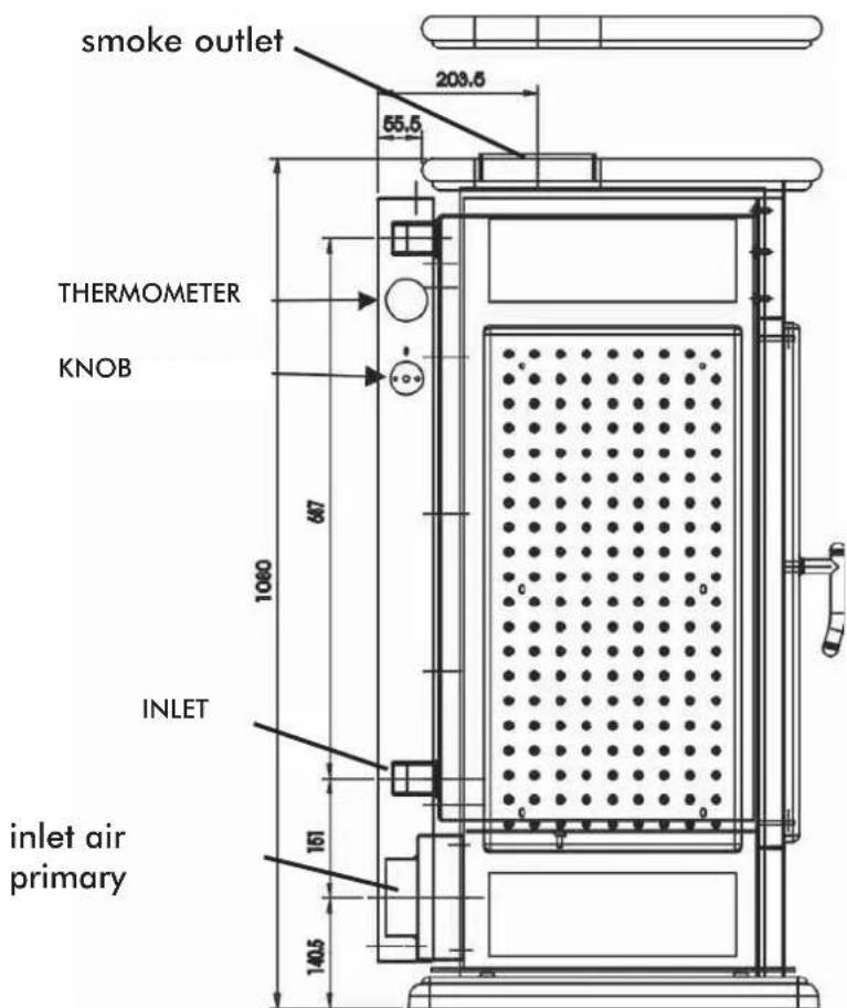
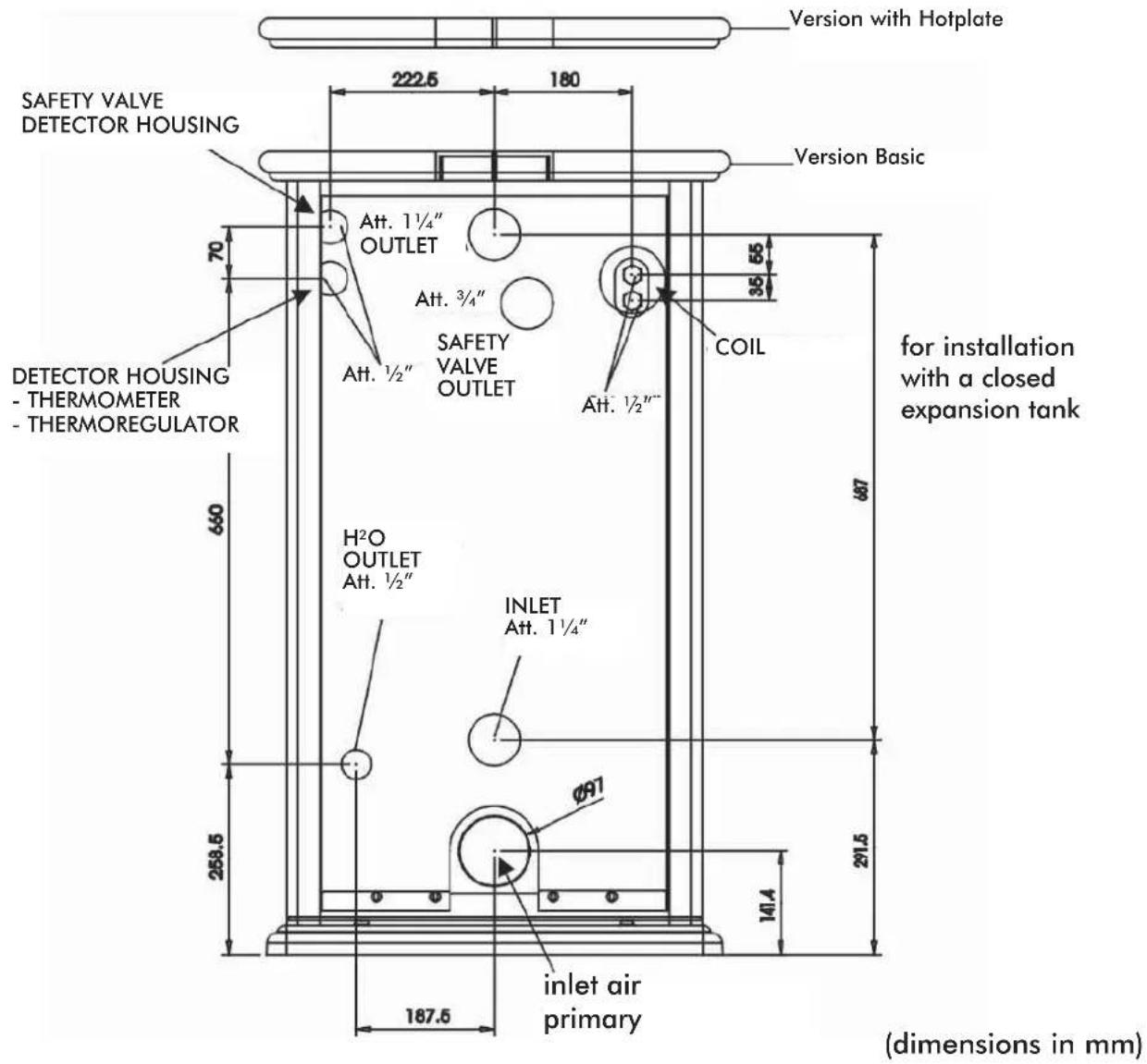
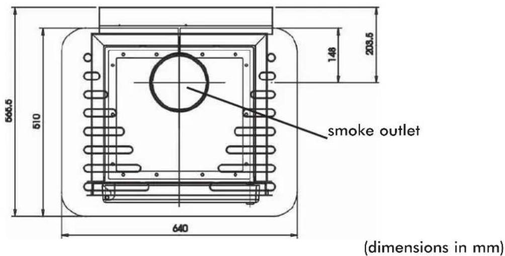
(dimensions in mm)
ONLY BOILER-STOVES WITH A COIL OPERATED BY A HEAT DISCHARGE VALVE MAY BE INSTALLED ON SYSTEMS WITH A CLOSED EXPANSION TANK.
In closed expansion tank installations:
- The installer is responsible for installing the system correctly. The installer must take Italian standards UNI 10683/2005 - 9615/90 - 10412:2 into consideration.
- Everything must be done by authorized staff according to Italian law 46/90.
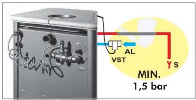
- The valve must be connected to the cooling circuit with a minimum pressure of 1.5 bars.
AL = Coil filling, always with a minimum pressure of 1.5 bars.
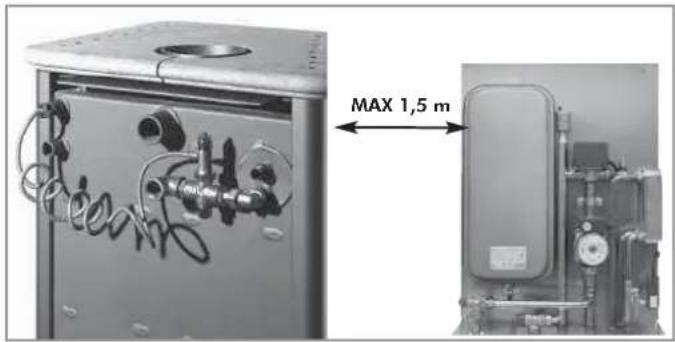
- Kits 5 or 6 must be installed 150~cm from the boiler-stove.
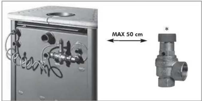
- An overpressure valve must be installed MAX 50 cm away. The valve is provided as standard by EDILKAMIN.
- A further expansion tank must be fitted in the system, of a size depending on the volume of water in the system itself.
1st year
- The safety valves must be checked at least once a year by staff authorized according to Italian law 46/90
KLIMA e WARM
for installation with an OPEN TANK
- The connections, commissioning and
verification of proper operation of the boiler-stoves must be carried out by qualified personnel, who can implement all connections in accordance with the laws in force, particularly with Italian D.M 37 Law No. 46/90, apart from complying with these instructions. - The boiler-stove and the system are filled with water that flows from the water inlet pipe (the diameter must not be less than 18mm ) to the open expansion tank.
- All the vents of the radiators must be opened during this phase so as to prevent air pockets from forming in the system which would obstruct the circulation of water.
NB:
- The open tank should be placed higher than 3m from the highest radiator and lower than 15m from boiler-stove.
- In any case, the tank must be high enough to create a greater pressure than that produced by the pump (circulator).
- The system must never be filled directly from the water mains as the pressure may be greater than that stipulated on the data plate of the boiler-stove.
- The safety pipe to the expansion tank must allow the water to flow freely, must not have taps and must be insulated properly.
- The water inlet pipe must not have taps nor curves.
- The maximum operating pressure must not exceed 1.5 bar
- The testing pressure is 3 bar.
- In places that reach very low temperatures, antifreeze liquid must be added to the water in the system.
- Never ignite the fire in the boiler-stove (not even as a test) unless the system is filled with water as this could cause irreparable damage.
- Connect the drains of the thermal relief valve (VST).
- The flow test of the system must be carried out with the expansion tank open.
- It is recommended to install a 6 bar safety valve on the hot sanitary water circuit so as to drain any excessive increase in the volume of the water in the heat exchanger.
- Place all the components of the system (circulator, heat exchanger, valves, etc.) in easily accessible points for routine and special maintenance procedures.
- It is recommended to prepare thermal insulation on the vaulted top part of the boiler
KLIMA/CS e WARM/CS
for installation with an CLOSED TANK
(additional regulations to those specified above).
- Be careful not to exceed 1.5 bar when filling the system.
- Only if a thermal relief valve actuates the coil can the boiler-stove be installed on a CLOSED TANK system.
- Consider the necessity of installing another CLOSED TANK.
- Make sure the drain is connected to the coil and the power supply is at least 1.5 bar.
- The upstream pressure of the cooling circuit must be at least 1.5 bar (UNI 10412/2 point 6.2).
Other than that described in this documentation, you are also asked to note the following UNI standards:
-
No. 10683/2005 - firewood heat generators: installation requirements
-
No. 9615/90 - calculating the internal dimensions of fireplaces
-
No. 10412:2 - hot water heating systems. Specific safety requirements for systems provided with residential solid fuel burning appliances and combined boiler, not exceeding a total nominal heat input of 35kW
Particularly:
Before carrying out any assembly it is important to verify compatibility of the appliance, as stipulated in UNI
10683/2005 standard, paragraphs 4.1 / 4.1.1 / 4.1.2.
-
When assembly is completed, the installer must implement "start-up operations" and issue documentation as required by UNI 10683/2005 standard in paragraphs 4.6 and 5, respectively.
-
The connections, commissioning and verification of proper operation of the boiler-stove must be carried out by qualified personnel, who can implement the electrical and plumbing connections as required by UNI standards
10683/2005, paragraph 4.5 and 10412:2, apart from complying with these assembly instructions.
LOCATION
The boiler-stove is delivered on a pallet covered with a cardboard box. Remove the boiler-stove from its packaging, check that the model is the one ordered, and make sure it has not been damaged during transport.
Any complaints must be made to the retailer (on the accompanying consignment note).
Before positioning the boiler-stove, make sure the flue is suitable for the smoke produced.
The boiler-stove must be level for correct operation.
Check the load-bearing capacity of the floor. If insufficient, it must be reinforced. If the boiler-stove is installed on a floor made of flammable material, it is advisable to place it on tiles
AIR INTAKE
The room where the boiler-stove is located must have an air intake with cross section of at least 200~cm^2 to ensure replenishment of the air consumed by combustion.
1
2
3
4
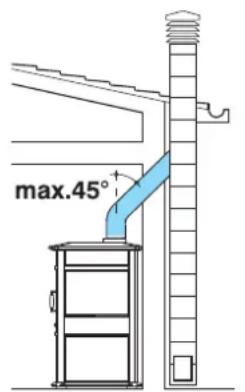
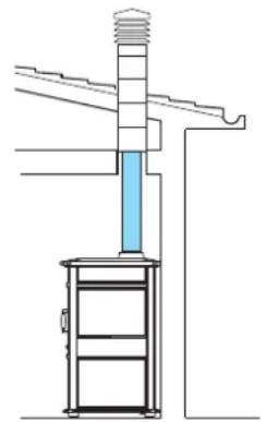
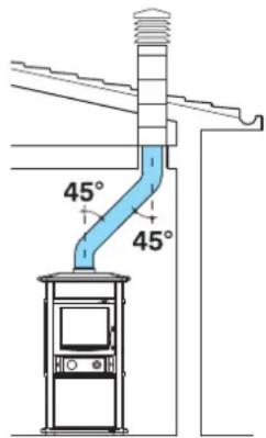
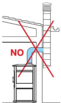
- SMOKE DUCT
The term smoke duct is taken to mean the duct which connects the boiler-stove smoke outlet pipe to the flue inlet.
The smoke duct must be made using non-flexible steel or ceramic pipes. Flexible metal or fibrocement pipes must not be used. Horizontal or downward sloping sections must be avoided. Any changes in cross-section must occur at the outlet from the boiler-stove, and not at the connection with the flue, for instance.
Bends of greater than 45^ are not allowed (see figures 1, 2, 3 and 4). The joint between the steel pipe and the boiler-stove smoke outlet must be sealed with high temperature mastic.
In addition to that mentioned above, please consider the indications stipulated in UNI 10683/2005 standard, paragraph 4.2: "connection to the smoke outlet system" and its subsections.
- SMOKE OUTLET
The chimney flue is intended as the channel that reaches the building roof from the thermo stove room of use.
The basic characteristics of the flue are:
capacity to support a smoke temperature of at least 450^
- suitably insulated to prevent condensate from forming;
- constant cross-section, almost vertical and devoid of bends greater than 45^ ;
preferably circular internal cross-section; in the case of rectangular cross-sections, the maximum ratio between the sides must be 1.5;
- internal cross-section with surface area equal at least to the size shown in the product specifications;
connected to only one hearth.
In the case of old or oversized flues, it is advisable to line them with stainless steel pipes of a suitable diameter and suitable insulation.
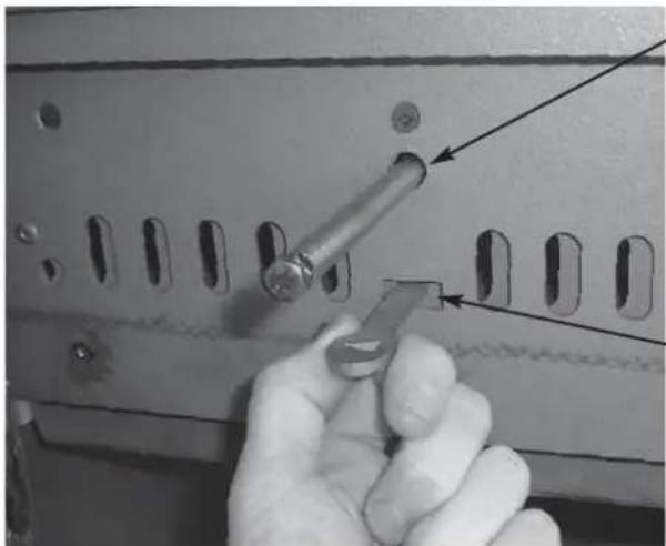
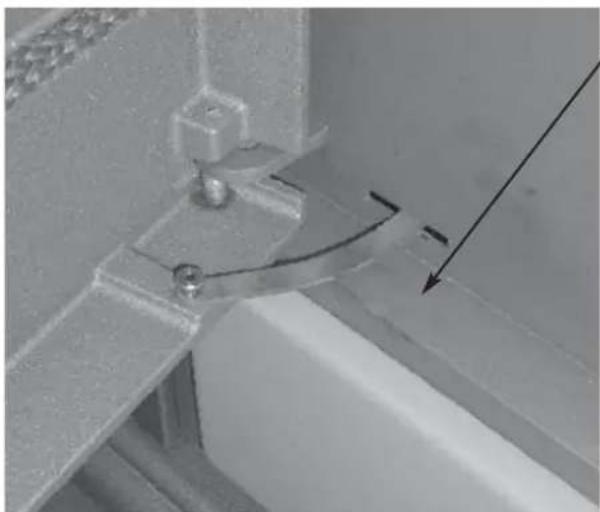
- BUTTERFLY VALVE
It is advisable to include a butterfly valve (shutter) on the smoke duct. The valve must be easy to operate and found in a place which allows it to be distinguished externally from the regulation knob. The valve must stay firm in the set position, and must not close automatically.
CHIMNEY
The basic features of the chimney pot are:
- internal cross-section at the base equal to the flue cross-section;
- outlet cross-section not less than twice the flue cross-section;
- a position in the open air above the roof beyond the reflux area.
INSTALLATION INFORMATION
- Wood-burning boiler-stoves must be installed "in a workmanlike manner" in compliance with the SAFETY REGULATIONS in force and, most importantly, by qualified expert staff.
- We advise you to read these instructions and general rules of conduct carefully in order to get the most from your wood-burning boiler-stove.
- Furthermore, due to the distinct characteristics of each installation, EdilKamin declines all responsibility for breakdown, damage or malfunction caused by failure to comply with these instructions for use
COMPATIBILITY CHECK WITH OTHER DEVICES
According to Italian standard UNI 10683/05, the boiler-stove must NOT be installed in the same room as extractor fans, type B gas equipment or devices which lower the pressure in the room.
Caution: If extractor fans operate in the same room or space where the device is installed, they may cause problems.
CAUTION: The boiler-stove has been designed to work with the door closed only. Heat is propagated by radiation and convection.
FIRE SAFETY DISTANCES
The boiler-stove must be installed in compliance with the following safety conditions:
- minimum distance at the sides from medium-level flammable materials: 80~cm
- minimum distance at the rear from medium-level flammable materials: 20~cm
- easily flammable materials must not be located less than 80~cm from the front of the boiler-stove;
- if the boiler-stove is installed on a flammable floor, a sheet of heat insulating material must be placed between the stove and the floor, which protrudes by at least 20cm at the sides and 40 cm at the front.
Objects made of flammable materials must not be placed on the boiler-stove or at less than the safety distance from it.
If the smoke outlet pipe is connected to walls made of wood or other flammable materials, it must be insulated with ceramic fibre or other materials with similar characteristics.
WATER CONNECTIONS:
THE BOILER-STOVE MUST NEVER BE RUN WITHOUT WATER IN THE SYSTEM. "WATERLESS" IGNITION DAMAGES THE BOILER-STOVE.
Plumbing must be carried out by qualified staff authorized to issue declarations of conformity in compliance with Italian law No. 46/90.
Water treatment
Add antifreeze, scale inhibitors and corrosion inhibitors. If the filling and top-up water has a hardness greater than 35^ , use a water softener to reduce it. Refer to Italian standard UNI 8065-1989 (Water treatment in domestic heating systems).
PRACTICAL NOTE
When connecting the outlet, inlet and drain piping (see page 25), fit suitable means to make moving the boiler-stove easy in the future (for example, flexible piping for the first 0.5m ).
The boiler-stove must be connected to the water pipes by qualified plumbers.
In Italy, refer to Italian Standards UNI 10683 and UNI 10412:2. In other countries, refer to the local laws in force.
The KLIMA and WARM boiler-stoves may be installed in two different types of system:
- Open systems (the most usual): with an open expansion tank.
- Closed systems (only possible with KLIMA CS and WARM CS) with a closed expansion tank.
Boiler-stove installation in an open system:
To install the KLIMA and WARM boiler-stoves with open expansion tank:
- The expansion tank must be located at more than 3m from the highest point of the last radiator to be heated or 2-3 metres above the boiler-stove if a plate heat exchanger is used.
- The height of the expansion tank must in any case create a greater pressure than that produced by the circulation pump.
- The expansion tank safety pipe must not be closed and must not be fitted with a cock.
- The expansion tank safety pipe must not be less than 28mm in diameter.
- The filling pipe must not be closed, and must not be fitted with cocks or bends.
- The filling pipe must not be less than 18mm in diameter.
The maximum working pressure must not be greater than 1.5 bars.
It must be tested at a pressure of 3 bars.
- Never fill the system directly with mains pressure water since this may be greater than the boiler-stove test pressure.
The boiler-stove and system must be filled through the open expansion tank by gravity through the filling pipe (not less than 18mm in diameter).
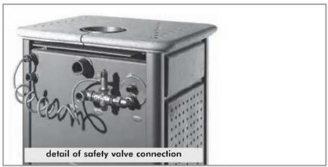
Connect the heat discharge valve (VST) and safety valve (VS) outlets.
- A residual current circuit breaker must be fitted upstream of the device and the whole boiler-stove electric circuit. The pump, the valve and the metal parts of the boiler-stove must also be earthed.
Compliance with regulations concerning earth connections is essential for the safety of people. - During this stage, open all radiator vents to prevent the formation of air pockets in the system which would prevent water circulation.
Boiler-stove installation with closed expansion tank:
To install the KLIMA CS and WARM CS boiler-stoves with a closed expansion tank, the boiler-stove must have a cooling coil with heat discharge valve.
An EDILKAMIN assembled kit must be used: kit 5 without domestic hot water production (code n.280590) or kit 6 with domestic hot water production (code n.280600) according to the case.
- The maximum working pressure must not be greater than 1.5 bars.
It must be tested at a pressure of 3 bars.
- Never fill the system directly with mains pressure water since this may be greater than the boiler-stove test pressure.
- Never turn on the fire in the boiler-stove (not even as a test) if the system is not filled with water; it could be irreversibly damaged.
- The system must be tested with the expansion tank open.
- It is advisable to install a 6 bar safety valve on the domestic hot water circuit to relieve the increase in water volume in the heat exchanger.
- Arrange all the system components (circulation pump, heat exchanger, valves, etc.) in easily accessible places for routine and special maintenance.
- EdilKamin is only liable for correct operation if the boiler-stove is used in compliance with the documents supplied with it.
- Assess the need for a further system expansion tank.
To make boiler-stove installation quicker and surer, EDILKAMIN offers assembled kits:
1-2-3-N3-N3 BIS-IDROKIT to install KLIMA and WARM with an open expansion tank.
- 5-6-IDROKIT to install KLIMA CS and Warm CS with a closed expansion tank.
The choice of kit depends on the type of system you wish to set up.
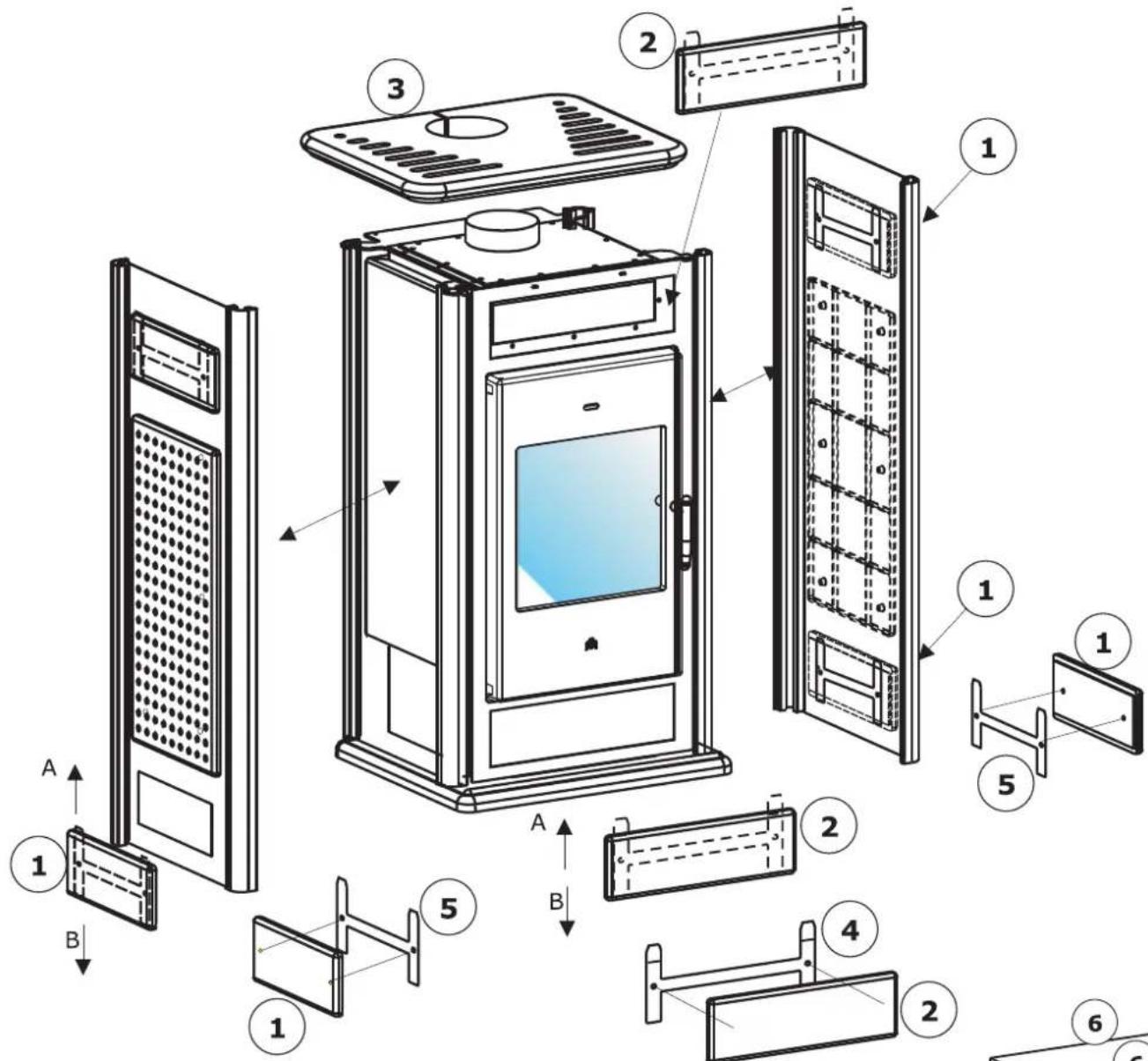
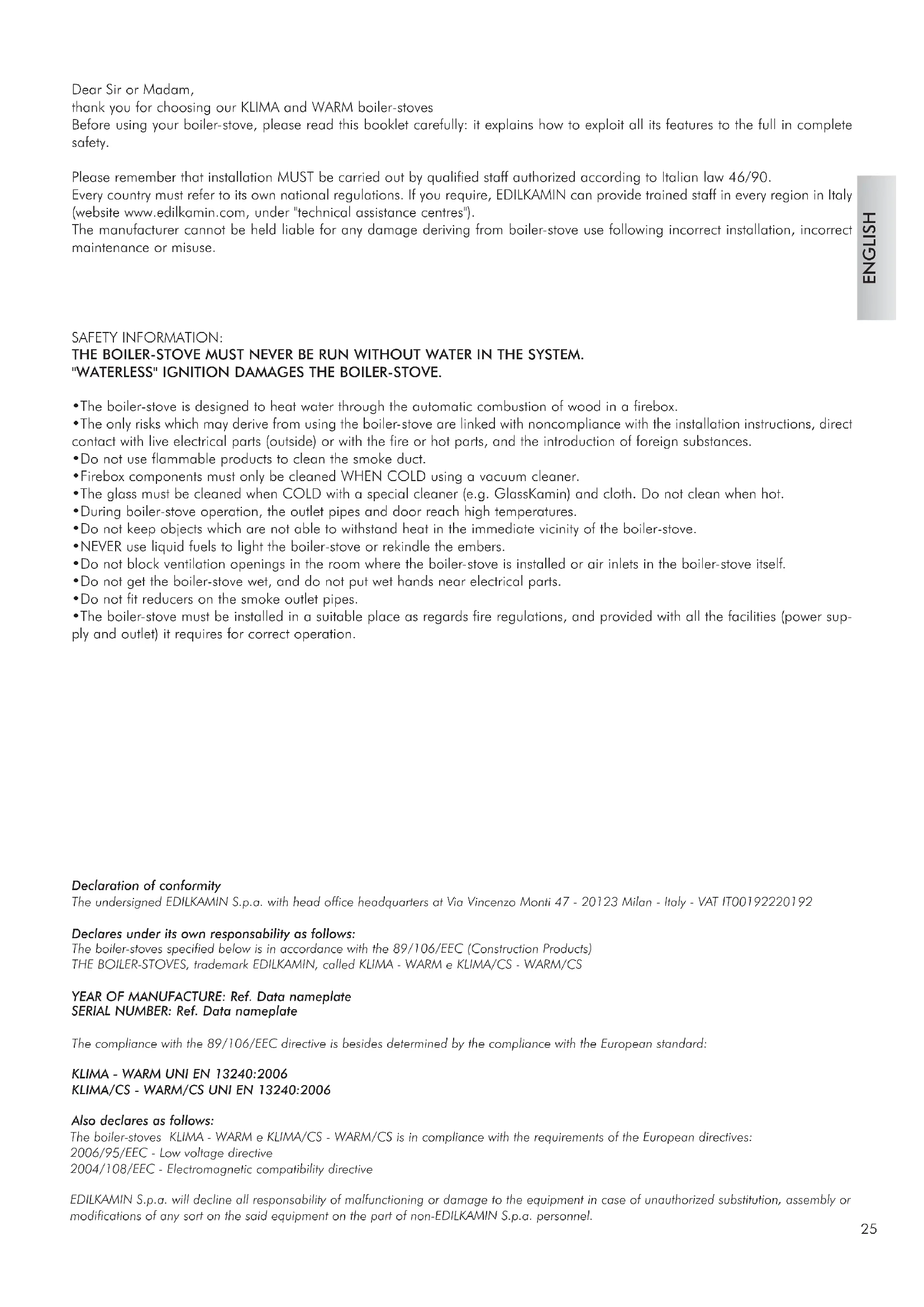
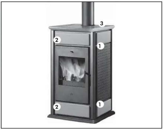
External covering assembly for BASIC WARM /KLIMA
If they are not already fitted (1), put the side panels into the grooves in the stove frame aluminium bars.
- Screw the metal bars (5) to the corresponding side ceramic tiles (1) using the screws provided.
- Place them into their housings in the side stove panels by slipping them in from above (A), then lock them in place by pushing them downwards (B).
- Screw the metal bars (4) to the corresponding front ceramic tiles (2) using the screws provided.
- Place them into their housings in the front stove panel by slipping them in from above (A), then lock them in place by pushing them downwards (B).
- Put the ceramic top (3) in place and centre it with the smoke outlet.
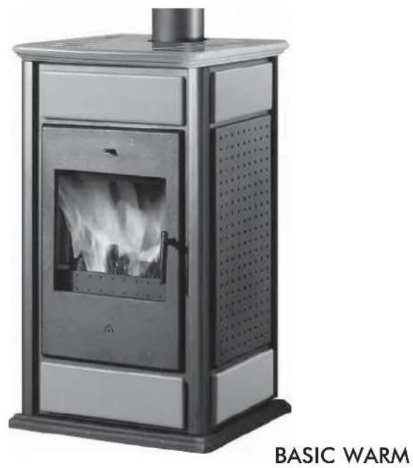
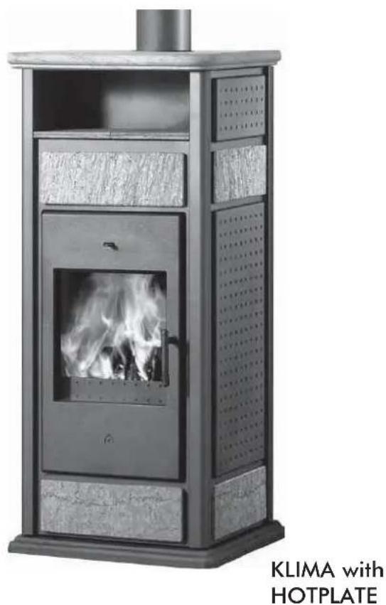
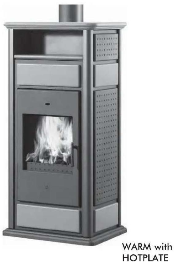
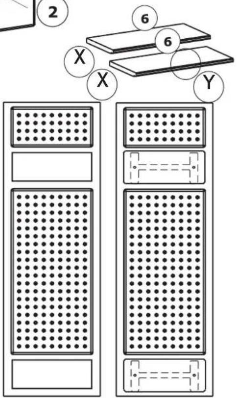
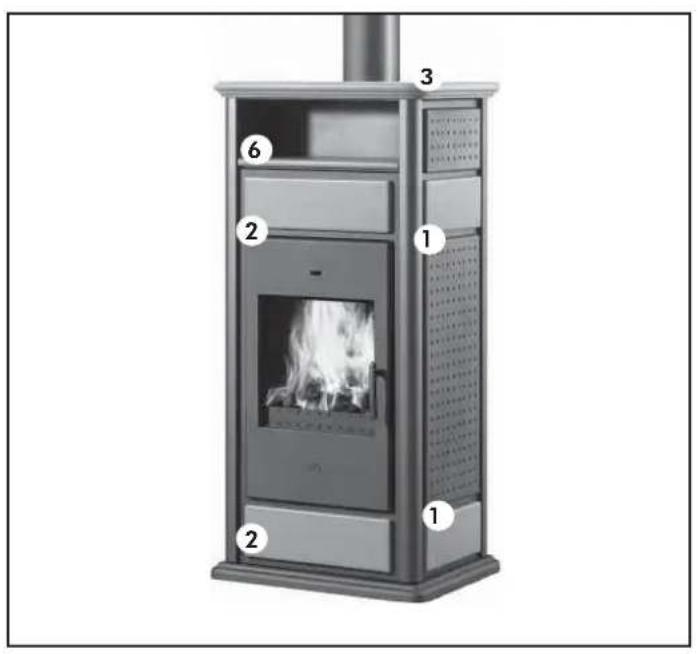
External covering assembly for WARM /KLIMA with HOTPLATE
- Proceed in the same way. See detail of side panels.
- After positioning the top (3), put the ceramic hotplate components in place (6)
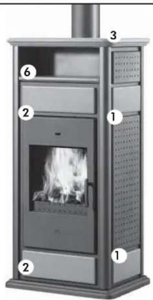
CERAMIC SETS BASIC WARM / KLIMA
Remove the tiles from the packaging and check the contents.
For BASIC WARM / KLIMA:
-4side files(1)
- 2 front tiles (2)
-1top(3)
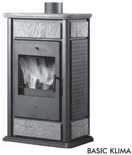
CERAMIC SETS WARM / KLIMA with hotplate
Remove the files from the packaging and check the contents.
For WARM / KLIMA with hotplate:
-4 side tiles (1)
- 2 front tiles (2)
-1top(3)
- 1 hotplate (6)
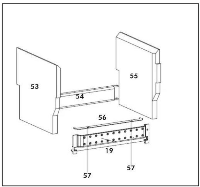
FIREBOX SCAMOLEX SET (cod. 624670)
-1 Large left firebox scamolex (53)
-1 Catch back firebox (54)
-1 Large right firebox scamolex (55)
-1 Stirrup listening scamolex (56)
- 2 Self-tapping screws M4,2x9 (57)
-1 Wood guard (19)
INSTALLATION SEQUENCE:
- Insert the rear fireplace stop (54), resting it on the bottom of the fireplace on the hearth.
- Insert the two right/left sides (53-55).
- Tighten the fastening bracket (56) to front fender (19) with supplied screws (57).
- Then insert the fender (19) in its original position.
- It is important to ensure that there is water in the boiler-stove and the system before igniting the boiler-stoves.
- The Company is responsible for the proper functioning of the product only if this is handled in accordance with the documentation supplied with the product itself.
Any unpleasant smells or smoke are caused by materials used during construction evaporating or drying.
This tends to die down after a few days.
N.B.: do not use alcohol, petrol (gasoline), kerosene or other liquid fuels to light the fire. Keep liquid fuels away from the fire. Do not use firefighters made from petroleum or chemical substances: they may cause serious damage to the firebox walls. Only use eco-friendly firefighters. Overloading (more kilos than in the table shown earlier) or excessively lively flames may damage the firebox compartment.
Practical advice
Incomplete combustion leads to excessive deposits on the heat exchanger. To avoid this, it is necessary to:
- burn dry wood;
make sure the firebox contains a good bed of embers before adding other wood; - load large diameter logs with other smaller ones;
make sure that at least one radiator is always on; - turn on the pump switch;
- fill the boiler-stove with a load of medium-small pieces of dry wood and light the fire;
- wait a few minutes until sufficient combustion is achieved;
-
adjust the combustion using the thermoregulator with thermostat;
-
oIt is recommended to keep the radiators closed in the room where the boiler-stoveis installed since the heat radiated from the opening of the boiler-stoves itself is enough.
Fuel and heating value
Combustion has been optimized from the technical point of view both as regards the design of the firebox and relevant air supply, and emissions. Only use natural seasoned wood or wood briquettes as fuel. Damp, freshly cut or unsuitably stored wood has a high water content. Therefore it burns badly, produces a lot of smoke and gives off little heat. Only use firewood seasoned for a minimum of two years in a dry ventilated place. In this case, the water content is less than 20% by weight. This leads to a fuel saving, since seasoned wood has a decidedly greater heating value. One kilo of dry wood produces between 2000 and 2500~kcal / kg according to type, whereas one kilo of dry wood of the same type after two years of seasoning produces between 3500 and 4000~kcal / kg .
Never use liquid fuels, such as petrol (gasoline), alcohol or similar substances. Never burn refuse.
Adding fuel
When "adding wood" it is advisable to use a protective glove to avoid accidental contact with hot parts. Open the door slowly. In this way, no vortexes are formed which may cause smoke to enter the room.
When is it time to add wood?
When the fuel has almost become embers.
During the combustion process
If the water temperature exceeds 90^ because of too much wood being placed in the hearth, the thermal relief valve will be activated and the acoustic signal heard.
In this case you must proceed as follows:
- Wait until the temperature is lower than 80^ ; check the warning lights on the electronic regulator
- The hot water tap can be opened to speed up the cooling process if the boiler-stove is equipped with hot sanitary water.
Cleaning the glass pane
The glass must be cleaned when COLD with a cloth and a few drops of special cleaning liquid (GlassKamin). Do not clean when the boiler-stove is operating.
Cleaning the flue
According to different laws in various countries, it is necessary to have authorized staff clean the flue.
This must be done before periods of boiler-stove use and every time a layer of soot and tar (easily flammable substances) can be seen on the inside of the duct. When deposits reach a thickness of 5 - 6mm , high temperatures and sparks may set them on fire with easily imaginable consequences both for the flue and your home. It is therefore advisable to clean the flue at least once a year or in any case when necessary.
Maintenance
Failure to perform maintenance shall forfeit the guarantee.
In the case of very frequent use of the thermo stove, cleaning the smoke channel more than once a year is recommended.
For the maintenance of the chimney flue, also consider UNI 10847/2000 single smoke systems for generators fueled with liquid and solid fuels:
Maintenance and control.
FAQ
The answers shown here summarize the information found in these specifications.
1) What do I need to have in order to install KLIMA or WARM?
A smoke outlet of at least 150~mm in diameter (the outlet must receive smoke from KLIMA or WARM only).
An air intake in the room of at least 200~cm^2
Outlet and inlet connections to the manifold. An outlet to the drain for the high temperature valve (in the version with coil).
2) Can I use the boiler-stove without connecting it to the domestic water system?
No. Use without water damages the boiler-slove.
3) Can I connect the boiler-stove inlet and outlet directly to a heat emitting unit (radiator)?
No, like all other water heaters, they must be connected to a manifold from which the water is distributed to the heat emitting units.
4) Can the KLIMA and WARM stoves also provide domestic hot water?
Domestic hot water may be produced using our kits 1 - 3 - N3 - N3 BIS (for open expansion tank installations) and 6 (for closed expansion tank installations), or produced and stored by one of our water heaters (see plumbing diagrams). This use reduces the power available to the radiators.
5) Does there have to be an air intake in the room?
Yes, to replenish the air in the room there must be an air intake of at least 200~cm^3 in diameter.
CHECK LIST
Read the entire specifications before using this list
Installation and setup
- Installation carried out by an authorized TAC which has issued the guarantee and maintenance booklet.
- Room ventilation.
The smoke duct/flue only receives smoke from the boiler-stove.
The smoke duct does not have:
90^ bends;
horizontal sections.
- The outlet pipes are made of a suitable material (stainless steel is recommended).
- Where pipes cross any flammable materials (e.g. wood), every precaution has been taken to avoid fire.
The plumbing has been declared as compliant with Italian law No. 46/90 by an authorized technician. - The heatable room dimensions have been suitably calculated considering the heating efficiency of the heat emitting units (radiators).
Use
The firewood used is good quality and not damp.
The heat exchange pipes and parts inside the firebox are clean.
The pressure (read on the gauge) is about 1- 1.5 bars.
REMEMBER NEVER TO
VACUUM-CLEAN HOT ASH
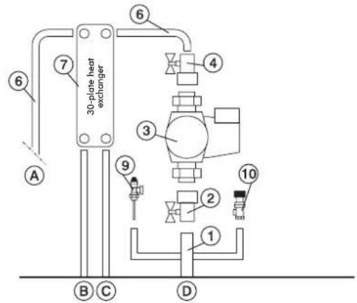
AN EXAMPLE OF A HYDRAULIC SYSTEM FOR A BOILER-STOVEWHTH HOT SANITARY WATER PRODUCTION
USING KIT 1
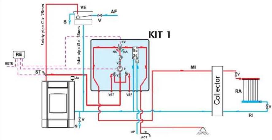
ACS: Hot Sanitary Water
AF: Cold Water
EV: 3-way Solenoid Valve
F: Flow Switch
MI: System Flow
NA: Normally Open
NC: Normally Closed
P: Pump (circulator)
RA: Radiators
RE: Electronic Regulator
RI: System Return
S: Drain
Sc 20: 20-plate Heat Exchanger
ST: Temperature Sensor
V: Volve
VE: Open Expansion Tank
VSP: 1.5 bar Pressurized Safety Valve
VST: Thermal Relief Valve
Ja: Automatic Relief Valve
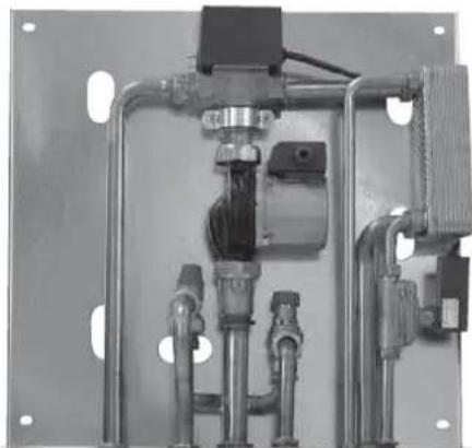
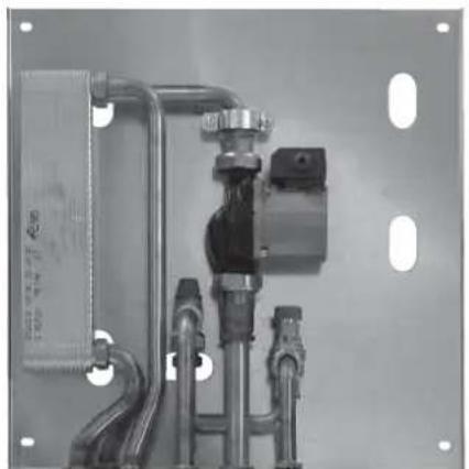
Kit 1 is designed to facilitate the work carried out by the installers. In fact, it consists of all the necessary components for the product to be properly installed.
NB: insulating mats must be applied so that the components of the kit are well-protected from the heat radiation emitted by the boiler-stoves.

1 1" Male Female Brass Collector
2 1"BallValve
3 Circulator with 112 Fasteners (219660)
4 1" Check Valve (261910)
5 1" Male-Female 3-way Solenoid Valve (143330)
6 Copper Fittings
7 30-plate Heat Exchanger for heat transfer with
the gas boiler circuit (216620)
8 20-plate Heat Exchanger for hot sanitary water production (205270)
9 3 / 4 Thermal Relief Valve (72940)
10 34"1.5 bar Safety Valve (143260)
11 Flussostato (220830)
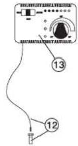
12 ½" Thermometer Well + Sensor (175960)
13 Electronic Regulator (220780)
A 3/4" System Return
B 34" System Flow
C 4" Boiler-stoves Return
D 1" Boiler-stoves Flow
E 12" Cold Sanitary Water
F 1/2" Hot Sanitary Water
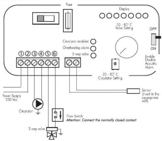
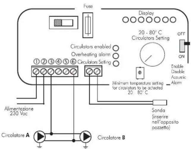
Electrical Connections
SELECTOR FUNCTIONS
Selector: OFF Everything is switched off
Selector: MAN Driven Circulator
Valve is set
Selector: AUTO Circulator is set
Valve is set
Alarm selection No acoustic signal in the
OFF position
KIT1 code 261880
AN EXAMPLE OF A HYDRAULIC SYSTEM FOR A BOILER-STOVETHAT DOES NOT PRODUCE HOT SANITARY WATER BUT HAS A WALL MOUNTED BOILER
USING KIT 2
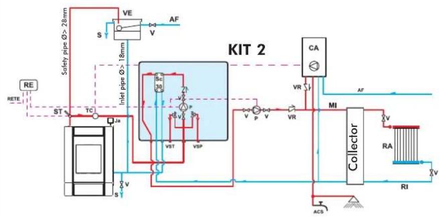
AF: Cold Water
CA: Wall Mounted Boiler
MI: System Flow
P: Pump (circulator)
RA: Radiators
RE: Electronic Regulator
RI: System Return
S:Drain
Ja: Automatic Relief Valve
Sc 30: 30-plate Heat Exchanger
ST: Temperature Sensor
V:Valve
VE: Open Expansion Tank
VR: Check Valve
VSP: 1.5 bar Pressurized Safety Valve
VST: Thermal Relief Valve
Kit 2 is designed to facilitate the work carried out by the installers. In fact, it consists of all the necessary components for the product to be properly installed.
NB: insulating mats must be applied so that the components of the kit are well-protected from the heat radiation emitted by the boiler-stoves.
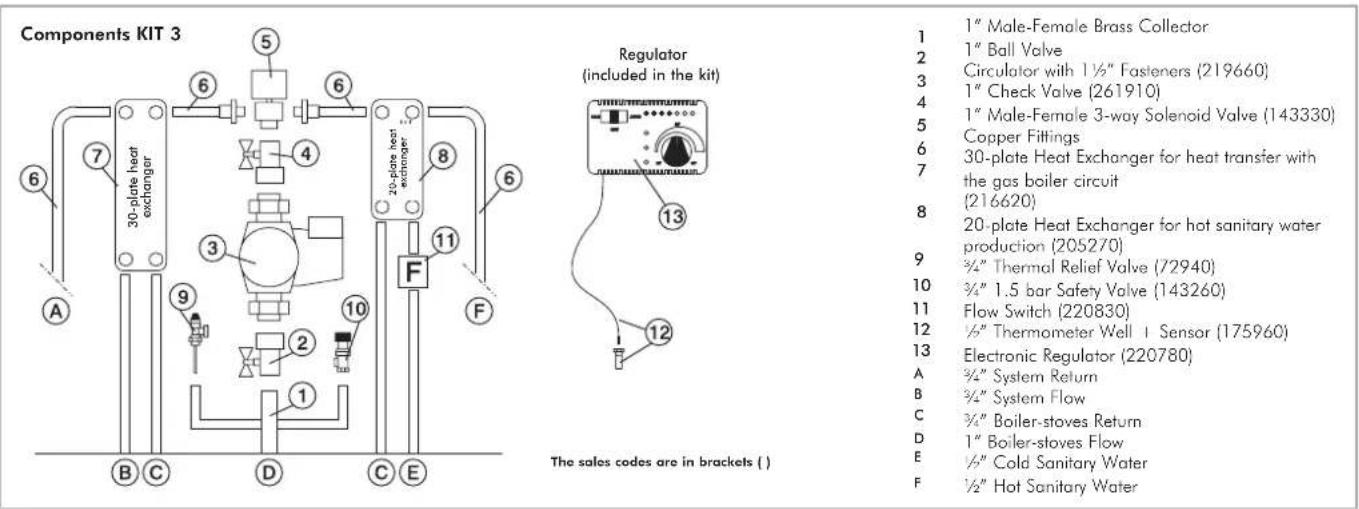
Components KIT 2
Regulator
(included in the kit)
The sales codes are in brackets []
1 1" Male-Female Brass Collector
2 1"BallValve
3 Circulator with 112 Fasteners (219660)
4 1" Check Valve (261910)
5 1" Male-Female 3-way Solenoid Valve (143330)
6 Copper Fittings
7 30-plate Heat Exchanger for heat transfer with
the gas boiler circuit (216620)
8 20-plate Heat Exchanger for hot sanitary water production (205270)
9 34"Thermal Relief Valve (72940)
10 3/4" 1.5 bar Safety Volve (143260)
11 Flow Switch (220830)
12 1/2" Thermometer Well + Sensor (175960)
13 Electronic Regulator (220780)
A 3/4" System Return
B 3/4" System Flow
C %"Boiler-stoves Return
D 1"Boiler-stoyes Flow
E 12" Cold Sanitary Water
F 12" Hot Sanitary Water
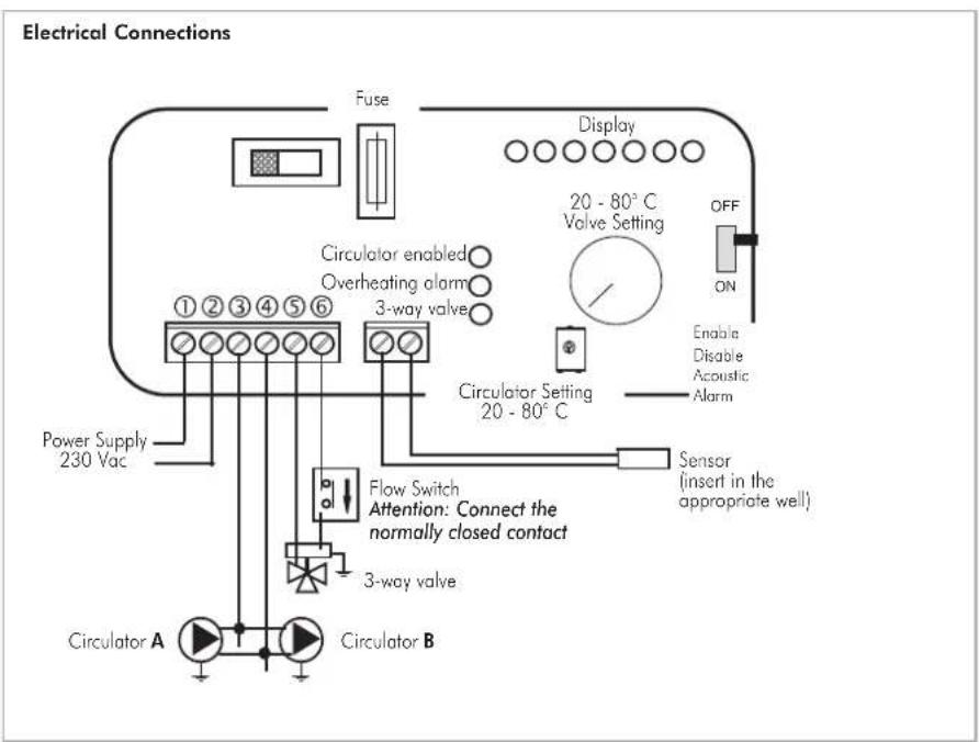
Electrical Connections
SELECTOR FUNCTIONS
Selector: OFF Everything is switched off
Selector: MAN Driven Circulator
Volve is set
Selector: AUTO Circulator is set
Volve is set
Alarm selection No acoustic signal in the
OFF position
KIT2
code 261890
AN EXAMPLE OF A HYDRAULIC SYSTEM FOR A THERMO FIREPLACEITH HOT SANITARY WATER PRODUCTION AND A WALL MOUNTED BOILER
USING
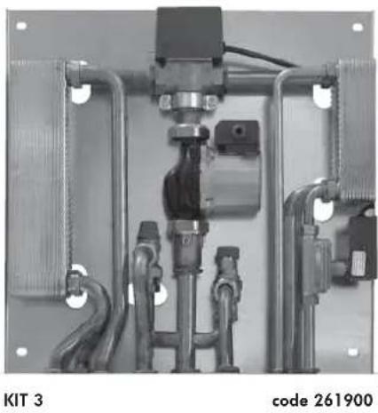
KIT 3
Kit 3 is designed to facilitate the work carried out by the installers. In fact, it consists of all the necessary components for the product to be properly installed.
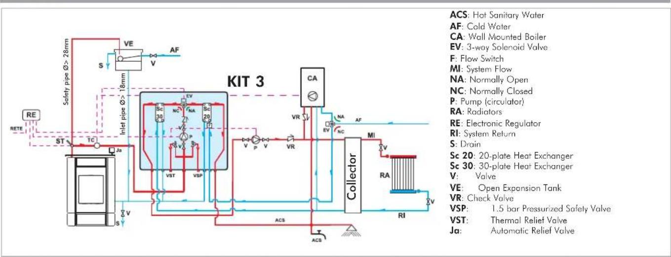
NB: insulating mats must be applied so that the components of the kit are well-protected from the heat radiation emitted by the boiler-stoves.
SELECTOR FUNCTIONS
Selector: OFF Everything is switched off
Selector: MAN Driven Circulator
Volve is set
Selector: AUTO Circulator is set
Volve is set
Alarm selection No acoustic signal in the
OFF position
AN EXAMPLE OF A HYDRAULIC SYSTEM FOR A THERMO FIREPLACEITH HOT SANITARY WATER PRODUCTION AND A WALL MOUNTED BOILER USING KIT N3
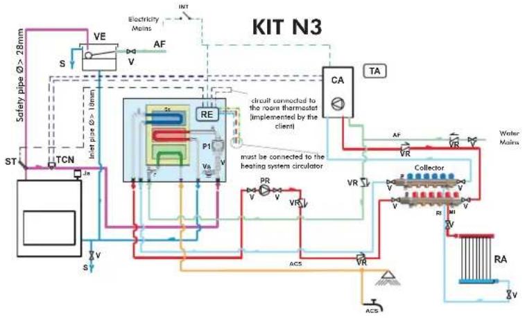
CA: Wall Mounted Boiler
PR: Pump (circulator)
P1: Primary circuit pump
RE: Electronic regulator
TA: Room thermostat
VE: Expansion Tank
Ja: Air refiet Volve
V:Intercept valve
VR: Retaining valve
ST: Temperature Sensor
F: Flow switch
Sc: Heat plate exchanger
EV: 3-way solenoid valve
RI: Heating system return
RA: Radiators
MI: Heating system flow
AF: Cold water
ACS: Hot sanitary water
S: Drain
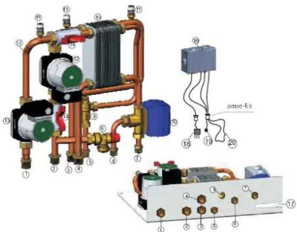
Kit N3 is designed to facilitate the work carried out by the installers. In fact, it consists of all the necessary components for the product to be properly installed.
NB: insulating mats must be applied so that the components of the kit are well-protected from the heat radiation emitted by the boiler-stoves.
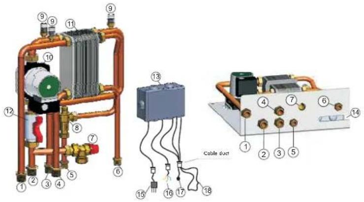
Components KIT N3
1 Heating system return G 3/4"
2 EDILKAMIN generator flow G 3/4"
3 EDILKAMIN generator return G 3/4"
4 Heating system flow G 3/4"
5 Cold sanitary water inlet G 1/2"
6 Hot water return to the sanitary system G 1/2"
7 Safety valve - temperature and pressure (90 °C - 3 bar)
8 Flow Switch
9 Air relief valve G 3/8"
10 EDILKAMIN generator circuit circulatior
11 3-way heat exchanger
12 Intercep valve G 1
13 Electronic regulator with wiring
14 Appropriate aperture for the cable duct to pass through
15 Power cable
16 Cables for the heating system circulator (phase, neutral, earth)
17 Temperature sensor
18 Room thermostat circuit
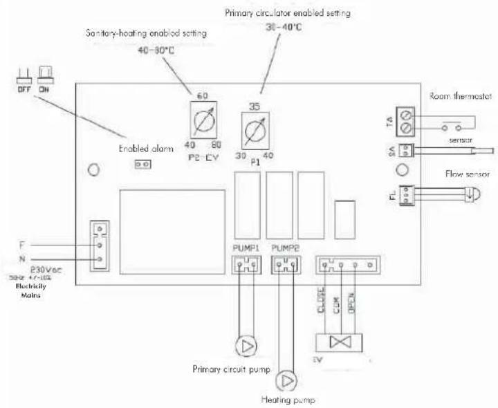
Electrical Connections
KIT N3
code 627690
AN EXAMPLE OF A HYDRAULIC SYSTEM FOR A BOILER-STOVEWHT HOT SANITARY WATER PRODUCTION AND A WALL MOUNTED BOILER
USING KIT N3 BIS
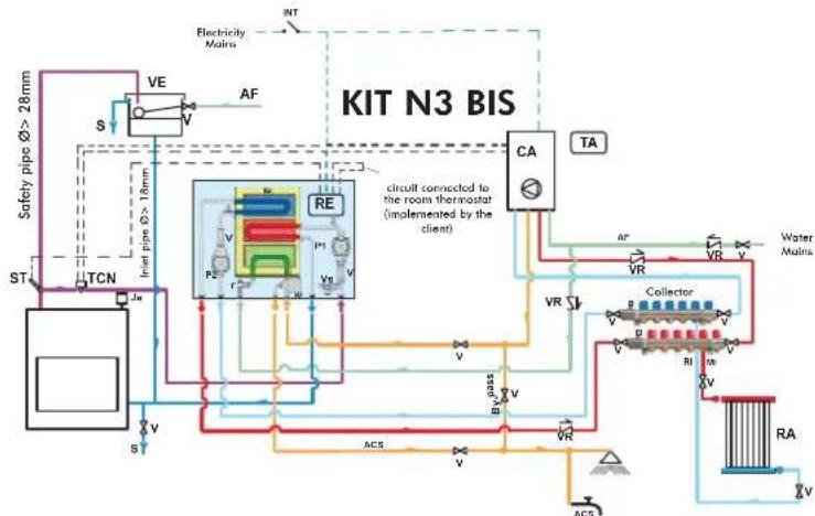
CA Wall Mounted Boiler
P2 Pump (circulator)
P1 Primary circuit pump
RE Electronic regulator
TA Room Thermostat
VE Expansion Tank
Ja Air Relief Volve
VInterceptvalve
VR Retaining valve
ST Temperature Sensor
F Flow switch
Sc Heat Plate Exchanger
EV 3-way Solenoid Valve
RI Heating system return
RA Radiators
MI Heating system flow
AF Cold Water
ACS Hot Sanitary Water
S Drain
INT Main switch
TCN Contact Thermostat
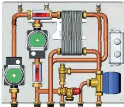
Kit N3 BIS is designed to facilitate the work carried out by the installers. In fact, it consists of all the necessary components for the product to be properly installed.
NB: insulating mats must be applied so that the components of the kit are well-protected from the heat radiation emitted by the boiler-stoves.
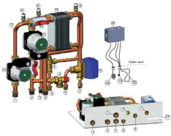
Components KIT N3 BIS
1 Heating system return G 3/4"
2 EDILKAMIN generator flow G 3/4"
3 EDILKAMIN generator return G 3/4"
4 Heating system flow G 3/4"
5 Cold sanitary water inlet G 1/2"
6 Hot water return to the sanitary system G 1/2"
7 Sanitary hot water inlet to the gas boiler G 1/2"
8 Safety valve - temperature and pressure (90 °C - 3bar)
9 Flow Switch
10 3-way deviation solenoid valve
11 Air relief valve G 3/8"
12 EDILKAMIN generator circuit circulor
13 Heating system circuit circulator
14 Intercept volve G 1
15 3-way heat exchanger
Electronic regulator with wiring
17 Appropriate aperture for the cable duct to pass through
18 Power cable
19 Temperature sensor
20 Room thermostat circuit
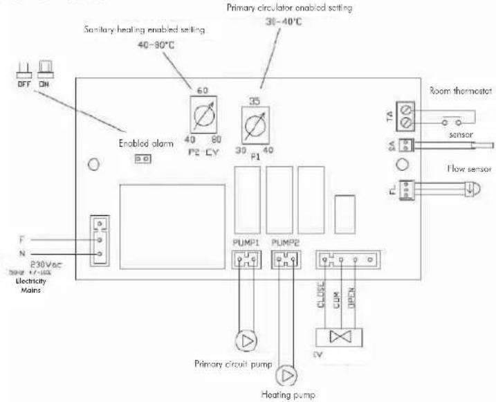
Electrical Connections
KIT N3 BIS
code 627860
AN EXAMPLE OF A HYDRAULIC SYSTEM FOR A BOILER-STOVETHAT PRODUCE AND STORES HOT SANITARY WATER AND HAS A WALL MOUNTED BOILER
USING IDROKIT
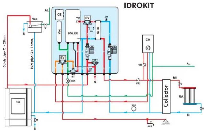
ACS: Hot Sanitary Water
AF: Cold Water
AL: Water Mains Supply
C: Filling/Top-Up Section
CE: Electronic Panel
EV: 3-way Solenoid Valve
NA: Normally O
NC: Normally Closed
GR:Pressure Reducer
Ja: Automatic Relief Valve
Jm: Manual Relief
MI: System Flow
MT:Thermostatic Mixer
P: Pump (circulator)
RA: Radiators
RI: System Return
S: Drain
SC30: 30-plate Heat Exchanger
ST: Temperature Sensor
TC: Contact Thermostat
TM: Thermo Boiler-stoves
V: Ball Valve
Ve: Open Expansion Tank
Vec: Closed Expansion Tank
VR: Check Valve
VSPT: Safety Pressure and Temperature Valve
VCA: Boiler
IDROKIT is designed to facilitate the work carried out by the installers. In fact, it consists of all the necessary components for the product to be properly installed.
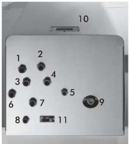
1 heating return
2 gas boiler hot sanitary water
3 boiler-stoveflow
4 drain
5 hot sanitary water
6 boiler-stovereturn
7 heating flow
8 water mains
thermostatic mixer setting
10 synoptic panel
11 auxiliary socket for a room thermostat
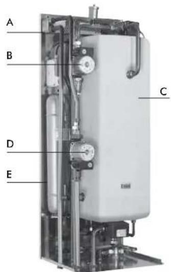
A 30-plate Heat Exchanger
B primary circulator (in the wood-fired version)
C 50-litre boiler
D heating system circulator
E closed expansion tank
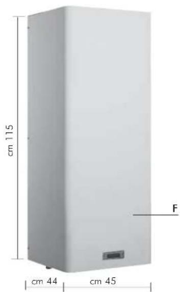
F boiler-stoves covering for exposed installation
IDROKIT
code 601740
AN EXAMPLE OF A HYDRAULIC SYSTEM FOR A THERMO BOILER-STOVES - ONLY HEATING
USING KIT 5
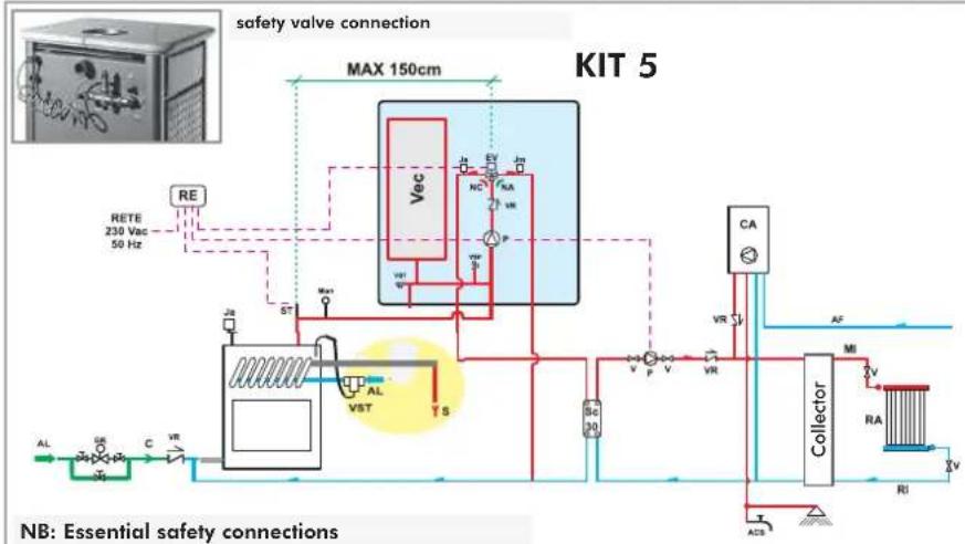
AL: Water Mains Supply
C: Filling/Top-Up Section
EV: 3-way Solenoid Valve
NA: Normally Open
NC: Normolly Closed
GR: Filling unit
Ja: Automatic Relief Valve
Jm: Manual Relief Valve
MAN: Manometer
MI: System Flow
P: Pump (circulator)
RA: Radiators
RE: Electronic Regulator PI: Sector Polity
KI: System Ketom
S! Dnain
ST: Temperature Sensor
V: Ball Valve
Vec: Closed Expansion Tank
VR: Check Valve
VSP: Pressurised Safety Valve
VST: Thermal Relief Valve
Kit 5 is designed to facilitate the work carried out by the installers. In fact, it consists of all the necessary components for the product to be properly installed.
NB: insulating mats must be applied so that the components of the kit are well protected from the heat radiation emitted by the boiler-stoves.
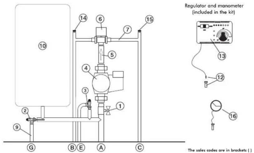
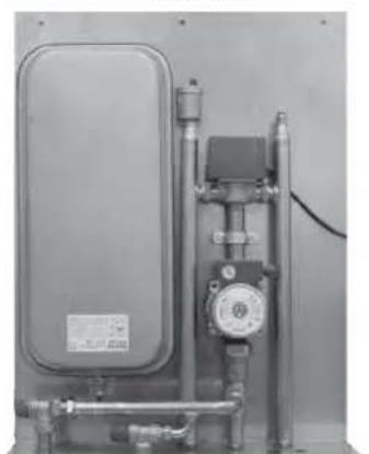
Components KIT 5
1 Ball Valve
2 Thermal Relief Valve (72940)
3 Pressure Relief Valve (284220)
4 Circulator (219660)
5 Fittings with 1" Check Valve (284180)
6 12 Male 3-way Solenoid Valve (283690)
7 Fittings
9 Temperature Relief Valve Nozzle
10 Closed Expansion Tank (283680)
12 1/2" Thermometer Well + Sensor (175960)
13 Electronic Regulator (220780)
14 3/8"Automatic Relief Valve (284750)
15 1/4" Manual Relief Valve (284170)
16 Manometer (269590)
Electrical Connections
SELECTOR FUNCTIONS
A Boiler-stoves Flow
B System return
C Boiler-stoves Return
Pressure Relief Valve
G Temperature Relief Valve
Selector: OFF Everything is switched off
Selector: MAN Driven Circulator
Valve is set
Selector: AUTO Circulator is set
Volve is set
Alarm selection No acoustic signal in the
OFF position
KIT5
code 280590
AN EXAMPLE OF A HYDRAULIC SYSTEM FOR A BOILER-STOVEWITH HOT SANITARY WATER PRODUCTION
USING KIT 6
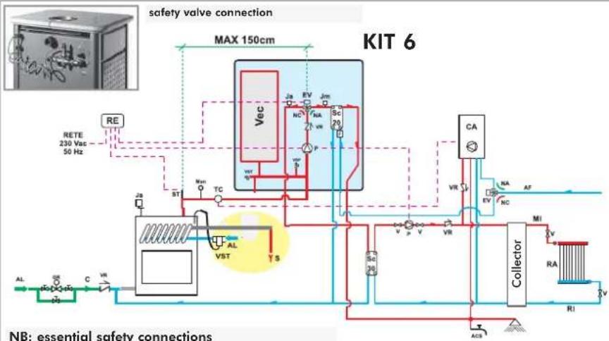
ACS: Hot Sanitary Water
AF: Cold Water
AL: Water Mains Supply
Filling/Top-Up Section 10.2.1
EV: 3-way Solenoid Valve NA
NA: Normally Open
NC: Normally Closed
F: Flow Switch
GR: Filling unit
Ja: Automatic Relief Valve
Jm: Manual Relief Valve
MAN: Manometer
MI: System Flow
P: Pump (circulator)
RA: Radiators
RE: Electronic Regulator
RI: System Return
S: Drain
SC: Plate Exchanger
ST: Temperature Sensor
V: Ball Valve
Vec: Closed Expansion Tank
VR: Check Valve
VSP: Pressurised Safety Valve
VST: Thermal Relief Valve
Kit 6 is designed to facilitate the work carried out by the installers. In fact, it consists of all the necessary components for the product to be properly installed.
NB: insulating mats must be applied so that the components of the kit are well protected from the heat radiation emitted by the boiler-stoves.
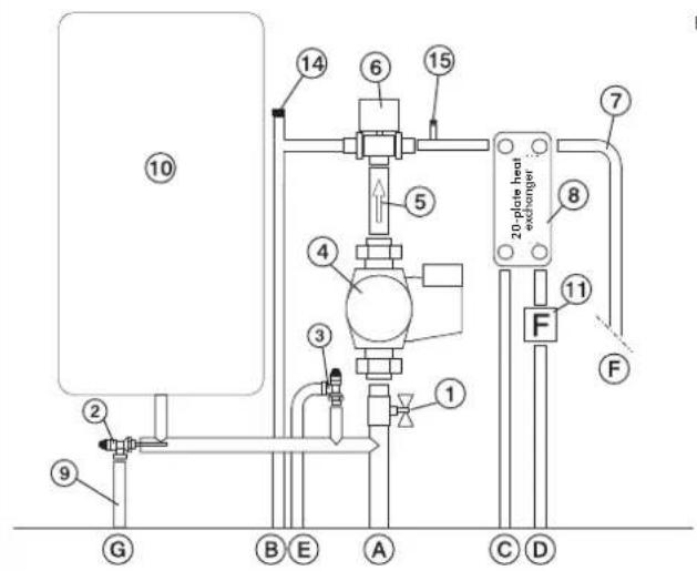
Componenti KIT 6
Regulator and manometer (included in the kit)
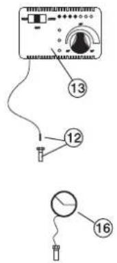
The sales codes are in brackets []
1 1 Ball Valve
2 Thermal Relief Volve (72940)
3 Pressure Relief Valve (284220)
4 Circulator (219660)
5 Fittings with 1" Check Valve (284180)
6 34" Male 3-way Solenoid Valve (283690)
7 Fittings
8 20-plate Heat Exchanger for hot sanitary water production (284300)
9 Temperature Relief Valve Nozzle
10 Closed Expansion Tank (283680)
11 Flow Switch (220830)
12 12 Thermometer Well + Sensor (175960)
13 Electronic Regulator (220780)
14 3/8Automatic Relief Valve (284750)
15 1/4" Manual Relief Valve (284170)
16 Manometer (269590)
A Boiler-stoves Return
B System Rerym
C Boiler-stoves Return
D Cold Sanitary Water
Pressure Relief Valve
E Hot Sanitary Water
G. Temperature Relief Valve
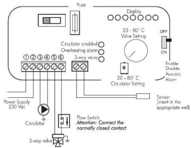
Electrical Connections
SELECTOR FUNCTIONS
Selector: OFF Everything is switched off
Selector: MAN Driven Circulator
Volve is set
Selector: AUTO Circulator is set
Volve is set
Alarm selection No acoustic signal in the
OFF position
KIT 6
code 280600
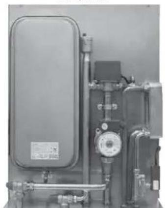
electronic regulator
IMPORTANT ADVICE REGARDING THE INSTALLATION
The connections, commissioning and verification of proper operation of the boiler-stoves must be carried out by qualified personnel, who can implement all connections in accordance with the laws in force, particularly with Italian Law No. 46/90, apart from complying with these instructions.
Compliance with regulations regarding the earth connection is fundamental for the safety of people.
It is obligatory to install a differential circuit breaker switch before the device and the entire electrical circuit of the thermo boiler-stoves. It is also obligatory to connect the pump, valve and metal parts of the boiler-stove to an earthing system.
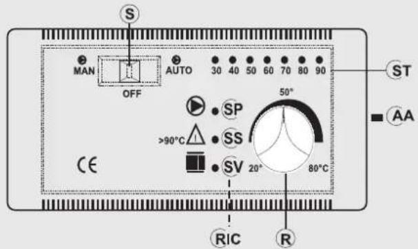
LEGEND
AA acoustic alarm switch
R way valve opening setting (KITS 1-3-5-6)
R circulators operation setting (KIT 2)
RIC internal pump setting
S MAN-OFF-AUTO selector
SP pump light
SS overheating light
ST temperature scale
SV 3-way valves light (KITS 1-3-5-6)
SV circulators setting (KIT 2)
fig. M
| Technical Data | |
| Power Supply (+15 - 10%) Vac 230 | |
| Degree of protection IP 40 | |
| Min/Max Room Temperature °C 0 to+50 | |
| Sensor range m 1,2 | |
| Thermometer °C 30 to 90 | |
| Maximum contact rating of the circulator W 400 | |
| Maximum contact rating of the 3-way valve W | 250 |
| Fuse mA | 500 |
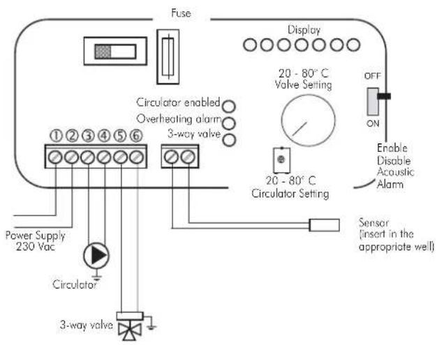
The electric control regulator allows you to monitor the operating conditions and is equipped with:
- MAN-OFF-AUTO selector (S)
-temperature scale (ST) - acoustic alarm (AA)
-3-way valve opening setting (R) (KIT1-3) - circulators operation setting (R) (KIT2)
- internal pump setting (RIC)
-3-way valve light (SV) (KIT1-KIT3) - circulators setting light (SV) (KIT2)
- overheating pump (SS)
- pump light (SP)
Operation
- Control device:
Thermometer
- Protection device
(acoustic alarm system):
Acoustic alarm (AA)
Overheating alarm (SS)
This system intervenes when the water temperature exceeds 90^ and warns the user to stop adding fuel.
The acoustic alarm can be disabled from the switch (AA).
However, the alarm remains enabled by means of the
overheating light (SS).
To restore the initial settings, the switch (AA) must be enabled after the water temperature in the boiler-stovehas cooled down.
- Power supply device
(circulation system):
- MAN-OFF-AUTO selector (S)
Pump light (SP)
The pump remains on when in manual mode and off when in
OFF mode. When in AUTO mode, the pump is activated by the system when the desired temperature is reached, by means of the internal setting (RIC), which ranges from 20 to 80^ (this is pre-set at 20^ ).
- Operation device (setting system):
-3-way valve opening setting (R)
-3-way valve operating light (SV)
When the fluid reaches the temperature set through the regulator, the 3-way valve diverts the fluid to the radiators and the operating light (SV) goes on.
When the temperature of the fluid drops below the set value, the system opens the electrical circuit and the 3-way valve bypasses the fluid directly to the boiler-stove.
Attention:
During normal operation check that the warning lights (SV) and (SP) are lit.
Positioning
The electronic regulator must be installed close to the thermo boiler-stoves. The sensor of the operation, protection and control devices must be placed directly on the boiler-stoveor at most on the flow pipe, no more than 5cm away from the boiler-stoveand in any case before any intercepting device. The sensor must be immersed in the well.
Installation
Follow this procedure to install the electronic regulator correctly: loosen the fastening screw, remove the cover and fasten it in place against the wall with the dowels supplied.
Then make the connections, paying utmost attention to the wiring diagram and pass the wires through ducts that are in conformity with the regulations in force. Put the cover back in place and tighten the screw.
The power supply must be disconnected from the mains and the AUTO-OFF-MAN selector (S) must be in the OFF position when all these operations are carried out.
Connect the brown wire (phase) and blue wire (neutral) of the 3-way Valve, respectively, to terminals 5 and 6 of the regulator.
Connect the yellow/green wire to the earth
Follow the assembly instructions contained in the package to connect the regulator to the system properly.
Madame, Monsieur,
UN ALLUMAGE "À SEC" RISQUE D'ENDOMMAGER LE THERMOPOÉLE.
2006/95/CEE - Directive Basse Tension
CA: Chaudière murale
RE: Regulateur electronic
TA:Thermostat d'ambiance
Composants KIT N3 BIS
E X E M P L E D S Y T I E N E H Y D R A U L I Q U E P O U R T H E R M O P O E L E S A V E C P R O D U C T I O N D E A U C H A UDE S A N I T A R E E N A C C U M U L A T I O N + C H A U D I E R E M U R A L E
AVEC UTILISATION D IDROKIT
(systeme circulation):
Para WARM / KLIMA BASE:
- 4 elementos laterales (1)
- 2 elementos anteriores (2)
-1tapa(3)

SET CERÁMICAS
WARM / KLIMA con calIENTapolatos
CON EL USO DE KIT N3 BIS

CA Caldera mural
P2 Bomba (circulador)
P1: Bomba circuito primario
INT: interruptor general
TCN: Termostat de contacto

Components KIT N3 BIS
KLIMA - WARM: UNI EN 13240:2006
KLIMA/CS - WARM/CS: UNI EN 13240:2006
P:Pumpe (Zirkulator)
RA:Heizkörper
RI: Rucklauf Anlage
S: Abfluss
P: Pumpe (Umwalzpumper)
RA: Heizkörper
P: Pomp (circulator)
RA: Radiators
PR: Pomp (circulator)
P1: Pomp primair circuit
P2 Pomp (circulator)
P1: Pomp primair circuit
RI: Retour installation
S: Afvoer


- SAFETY INFORMATION:
- THE BOILER-STOVE MUST NEVER BE RUN WITHOUT WATER IN THE SYSTEM.
- "WATERLESS" IGNITION DAMAGES THE BOILER-STOVE.
- Declaration of conformity
- Declares under its own responsibility as follows:
- YEAR OF MANUFACTURE: Ref. Data nameplate
- SERIAL NUMBER: Ref. Data nameplate
- KLIMA - WARM UNI EN 13240:2006
- KLIMA/CS - WARM/CS UNI EN 13240:2006
- Also declares as follows:
- NOTES on fuel:
- OPERATING PRINCIPLE/TECHNICAL DATA
- PRIMARY AIR REGULATION (for combustion)
- AUTOMATIC SMOKE BY-PASS VALVE
- SECONDARY AIR REGULATION
- AUTOMATIC DOOR CLOSURE
- ONLY BOILER-STOVES WITH A COIL OPERATED BY A HEAT DISCHARGE VALVE MAY BE INSTALLED ON SYSTEMS WITH A CLOSED EXPANSION TANK.
- 1st year
- KLIMA e WARM
- for installation with an OPEN TANK
- NB:
- KLIMA/CS e WARM/CS
- for installation with an CLOSED TANK
- LOCATION
- AIR INTAKE
- - SMOKE DUCT
- - SMOKE OUTLET
- - BUTTERFLY VALVE
- CHIMNEY
- INSTALLATION INFORMATION
- COMPATIBILITY CHECK WITH OTHER DEVICES
- FIRE SAFETY DISTANCES
- WATER CONNECTIONS:
- THE BOILER-STOVE MUST NEVER BE RUN WITHOUT WATER IN THE SYSTEM. "WATERLESS" IGNITION DAMAGES THE BOILER-STOVE.
- Water treatment
- PRACTICAL NOTE
- Boiler-stove installation in an open system:
- Boiler-stove installation with closed expansion tank:
- External covering assembly for BASIC WARM /KLIMA
- External covering assembly for WARM /KLIMA with HOTPLATE
- CERAMIC SETS BASIC WARM / KLIMA
- CERAMIC SETS WARM / KLIMA with hotplate
- FIREBOX SCAMOLEX SET (cod. 624670)
- INSTALLATION SEQUENCE:
- - It is important to ensure that there is water in the boiler-stove and the system before igniting the boiler-stoves.
- Practical advice
- Fuel and heating value
- During the combustion process
- Cleaning the glass pane
- Cleaning the flue
- Maintenance
- FAQ
- CHECK LIST
- Read the entire specifications before using this list
- Use
- SELECTOR FUNCTIONS
- Kit 2 is designed to facilitate the work carried out by the installers. In fact, it consists of all the necessary components for the product to be properly installed.
- USING IDROKIT
- Kit 6 is designed to facilitate the work carried out by the installers. In fact, it consists of all the necessary components for the product to be properly installed.
- electronic regulator
- IMPORTANT ADVICE REGARDING THE INSTALLATION
- LEGEND
- Operation
- - Control device:
- - Protection device
- (acoustic alarm system):
- - Power supply device
- (circulation system):
- - Operation device (setting system):
- Attention:
- Positioning
- Installation
- SET CERÁMICAS
Brand : EDILKAMIN
Model : Klima
Category : Pan