GWS 15125 CIEP Professional - Coffee grinder BOSCH - Free user manual and instructions
Find the device manual for free GWS 15125 CIEP Professional BOSCH in PDF.
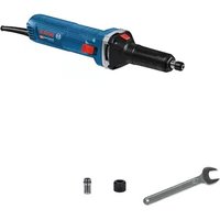
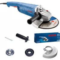
| Technical Specifications | BOSCH GWS 15125 CIEP Professional grinder, 1500 W power, 125 mm disc diameter, no-load speed of 11,500 rpm. |
|---|---|
| Usage | Ideal for grinding, cutting, and sanding various materials such as metal and concrete. |
| Maintenance and Repair | Regularly check carbon brushes, clean ventilation openings, lubricate moving parts if necessary. |
| Safety | Equipped with a disc guard, safety switch, and an additional handle for better grip. |
| General Information | Weight of 2.5 kg, 2-year warranty, compliant with European safety standards. |
Frequently Asked Questions - GWS 15125 CIEP Professional BOSCH
User questions about GWS 15125 CIEP Professional BOSCH
0 question about this device. Answer the ones you know or ask your own.
Ask a new question about this device
Download the instructions for your Coffee grinder in PDF format for free! Find your manual GWS 15125 CIEP Professional - BOSCH and take your electronic device back in hand. On this page are published all the documents necessary for the use of your device. GWS 15125 CIEP Professional by BOSCH.
USER MANUAL GWS 15125 CIEP Professional BOSCH
YkpaHcbKa ..CtoPiHa 220
Kaak. 5et 233
www.bosch-pt.com/serviceaddresses
Entsorgung
General Power Tool SafetyWarnings
WARNING
Read all safety warnings, instructions, illustrations and specifica
tions provided with this power tool. Failure to follow all instructions listed below may result in electric shock, fire and/ or serious injury.
Save all warnings and instructions for future reference.
The term "power tool" in the warnings refers to your mains-operated (corded) power tool or battery-operated (cordless) power tool.
Work area safety
- Keep work area clean and well lit. Cluttered or dark areas invite accidents.
Do not operate power tools in explosive atmospheres, such as in the presence of flammable liquids, gases or dust. Power tools create sparks which may ignite the dust or fumes. - Keep children and bystanders away while operating a power tool. Distractions can cause you to lose control.
Electrical safety
Power tool plugs must match the outlet. Never modify the plug in any way. Do not use any adapter plugs with earthed (grounded) power tools. Unmodified plugs and matching outlets will reduce risk of electric shock.
- Avoid body contact with earthed or grounded surfaces, such as pipes, radiators, ranges and refrigerators. There is an increased risk of electric shock if your body is earthed or grounded.
Do not expose power tools to rain or wet conditions. Water entering a power tool will increase the risk of electric shock.
Do not abuse the cord. Never use the cord for carrying, pulling or unplugging the power tool. Keep cord away from heat, oil, sharp edges or moving parts. Damaged or entangled cords increase the risk of electric shock.
When operating a power tool outdoors, use an extension cord suitable for outdoor use. Use of a cord suitable for outdoor use reduces the risk of electric shock.
If operating a power tool in a damp location is unavoidable, use a residual current device (RCD) protected supply. Use of an RCD reduces the risk of electric shock.
Personal safety
Stay alert, watch what you are doing and use common sense when operating a power tool. Do not use a power tool while you are tired or under the influence of drugs, alcohol or medication. A moment of inattention while operating power tools may result in serious personal injury.
Use personal protective equipment. Always wear eye protection. Protective equipment such as a dust mask, non-skid safety shoes, hard hat or hearing protection used for appropriate conditions will reduce personal injuries.
Prevent unintentional starting. Ensure the switch is in the off-position before connecting to power source and/or battery pack, picking up or carrying the tool. Carrying power tools with your finger on the switch or energising power tools that have the switch on invites accidents.
- Remove any adjusting key or wrench before turning the power tool on. A wrench or a key left attached to a rotating part of the power tool may result in personal injury.
Do not overreach. Keep proper footing and balance at all times. This enables better control of the power tool in unexpected situations.
Dress properly. Do not wear loose clothing or jewellery. Keep your hair and clothing away from moving parts. Loose clothes, jewellery or long hair can be caught in moving parts.
If devices are provided for the connection of dust extraction and collection facilities, ensure these are connected and properly used. Use of dust collection can reduce dust-related hazards.
Do not let familiarity gained from frequent use of tools allow you to become complacent and ignore tool safety principles. A careless action can cause severe injury within a fraction of a second.
Power tool use and care
Do not force the power tool. Use the correct power tool for your application. The correct power tool will do the job better and safer at the rate for which it was designed.
Do not use the power tool if the switch does not turn it on and off. Any power tool that cannot be controlled with the switch is dangerous and must be repaired.
- Disconnect the plug from the power source and/or remove the battery pack, if detachable, from the power tool before making any adjustments, changing accessories, or storing power tools. Such preventive safety measures reduce the risk of starting the power tool accidentally.
- Store idle power tools out of the reach of children and do not allow persons unfamiliar with the power tool or these instructions to operate the power tool. Power tools are dangerous in the hands of untrained users.
20|English
- Maintain power tools and accessories. Check for misalignment or binding of moving parts, breakage of parts and any other condition that may affect the power tool's operation. If damaged, have the power tool repaired before use. Many accidents are caused by poorly maintained power tools.
- Keep cutting tools sharp and clean. Properly maintained cutting tools with sharp cutting edges are less likely to bind and are easier to control.
Use the power tool, accessories and tool bits etc. in accordance with these instructions, taking into account the working conditions and the work to be performed. Use of the power tool for operations different from those intended could result in a hazardous situation. - Keep handles and grasping surfaces dry, clean and free from oil and grease. Slippery handles and grasping surfaces do not allow for safe handling and control of the tool in unexpected situations.
Service
Have your power tool serviced by a qualified repair person using only identical replacement parts. This will ensure that the safety of the power tool is maintained.
Safety warnings for angle grinder
Safety warnings common for grinding, sanding, wire brushing or cutting-off operations:
This power tool is intended to function as a grinder, sander, wire brush, hole cutter or cut-off tool. Read all safety warnings, instructions, illustrations and specifications provided with this power tool. Failure to follow all instructions listed below may result in electric shock, fire and/or serious injury.
Operations such as polishing are not to be performed with this power tool. Operations for which the power tool was not designed may create a hazard and cause personal injury.
Do not convert this power tool to operate in a way which is not specifically designed and specified by the tool manufacturer. Such a conversion may result in a loss of control and cause serious personal injury.
Do not use accessories which are not specifically designed and specified by the tool manufacturer. Just because the accessory can be attached to your power tool, it does not assure safe operation.
The rated speed of the accessory must be at least equal to the maximum speed marked on the power tool. Accessories running faster than their rated speed can break and fly apart.
The outside diameter and the thickness of your accessory must be within the capacity rating of your power tool. Incorrectly sized accessories cannot be adequately guarded or controlled.
The dimensions of the accessory mounting must fit the dimensions of the mounting hardware of the power tool. Accessories that do not match the mounting
hardware of the power tool will run out of balance, vibrate excessively and may cause loss of control.
Do not use a damaged accessory. Before each use inspect the accessory such as abrasive wheels for chips and cracks, backing pad for cracks, tear or excess wear, wire brush for loose or cracked wires. If power tool or accessory is dropped, inspect for damage or install an undamaged accessory. After inspecting and installing an accessory, position yourself and bystanders away from the plane of the rotating accessory and run the power tool at maximum no-load speed for one minute. Damaged accessories will normally break apart during this test time.
Wear personal protective equipment. Depending on application, use face shield, safety goggles or safety glasses. As appropriate, wear dust mask, hearing protectors, gloves and workshop apron capable of stopping small abrasive or workpiece fragments. The eye protection must be capable of stopping flying debris generated by various applications. The dust mask or respirator must be capable of filtrating particles generated by the particular application. Prolonged exposure to high intensity noise may cause hearing loss.
- Keep bystanders a safe distance away from work area. Anyone entering the work area must wear personal protective equipment. Fragments of workpiece or of a broken accessory may fly away and cause injury beyond immediate area of operation.
Hold the power tool by insulated gripping surfaces only, when performing an operation where the cutting accessory may contact hidden wiring or its own cord. Cutting accessory contacting a "live" wire may make exposed metal parts of the power tool "live" and could give the operator an electric shock.
Position the cord clear of the spinning accessory. If you lose control, the cord may be cut or snagged and your hand or arm may be pulled into the spinning accessory.
- Never lay the power tool down until the accessory has come to a complete stop. The spinning accessory may grab the surface and pull the power tool out of your control.
Do not run the power tool while carrying it at your side. Accidental contact with the spinning accessory could snag your clothing, pulling the accessory into your body.
Regularly clean the power tool's air vents. The motor's fan will draw the dust inside the housing and excessive accumulation of powdered metal may cause electrical hazards.
Do not operate the power tool near flammable materials. Sparks could ignite these materials.
Do not use accessories that require liquid coolants. Using water or other liquid coolants may result in electrocution or shock.
Kickback and related warnings:
Kickback is a sudden reaction to a pinched or snagged rotating wheel, backing pad, brush or any other accessory. Pinching or snagging causes rapid stalling of the rotating accessory which in turn causes the uncontrolled power tool to be forced in the direction opposite of the accessory's rotation at the point of the binding.
For example, if an abrasive wheel is snagged or pinched by the workpiece, the edge of the wheel that is entering into the pinch point can dig into the surface of the material causing the wheel to climb out or kick out. The wheel may either jump toward or away from the operator, depending on direction of the wheel's movement at the point of pinching. Abrasive wheels may also break under these conditions. Kickback is the result of power tool misuse and/or incorrect operating procedures or conditions and can be avoided by taking proper precautions as given below.
- Maintain a firm grip with both hands on the power tool and position your body and arms to allow you to resist kickback forces. Always use auxiliary handle, if provided, for maximum control over kickback or torque reaction during start-up. The operator can control torque reactions or kickback forces, if proper precautions are taken.
Never place your hand near the rotating accessory. Accessory may kickback over your hand.
Do not position your body in the area where power tool will move if kickback occurs. Kickback will propel the tool in direction opposite to the wheel's movement at the point of snagging. - Use special care when working corners, sharp edges, etc. Avoid bouncing and snagging the accessory. Corners, sharp edges or bouncing have a tendency to snag the rotating accessory and cause loss of control or kickback.
Do not attach a saw chain woodcarving blade, segmented diamond wheel with a peripheral gap greater than 10mm or toothed saw blade. Such blades create frequent kickback and loss of control.
Safety warnings specific for grinding and cutting-off operations:
- Use only wheel types that are specified for your power tool and the specific guard designed for the selected wheel. Wheels for which the power tool was not designed cannot be adequately guarded and are unsafe.
The grinding surface of centre depressed wheels must be mounted below the plane of the guard lip. An improperly mounted wheel that projects through the plane of the guard lip cannot be adequately protected.
The guard must be securely attached to the power tool and positioned for maximum safety, so the least amount of wheel is exposed towards the operator. The guard helps to protect the operator from broken wheel fragments, accidental contact with wheel and sparks that could ignite clothing.
Wheels must be used only for specified applications. For example: do not grind with the side of cut-off
wheel. Abrasive cut-off wheels are intended for peripheral grinding, side forces applied to these wheels may cause them to shatter.
Always use undamaged wheel flanges that are of correct size and shape for your selected wheel. Proper wheel flanges support the wheel thus reducing the possibility of wheel breakage. Flanges for cut-off wheels may be different from grinding wheel flanges.
Do not use worn down wheels from larger power tools. A wheel intended for larger power tool is not suitable for the higher speed of a smaller tool and may burst.
When using dual purpose wheels always use the correct guard for the application being performed. Failure to use the correct guard may not provide the desired level of guarding, which could lead to serious injury.
Additional safety warnings specific for cutting-off operations:
Do not "jam" the cut-off wheel or apply excessive pressure. Do not attempt to make an excessive depth of cut. Overstressing the wheel increases the loading and susceptibility to twisting or binding of the wheel in the cut and the possibility of kickback or wheel breakage.
Do not position your body in line with and behind the rotating wheel. When the wheel, at the point of operation, is moving away from your body, the possible kickback may propel the spinning wheel and the power tool directly at you.
- When the wheel is binding or when interrupting a cut for any reason, switch off the power tool and hold it motionless until the wheel comes to a complete stop. Never attempt to remove the cut-off wheel from the cut while the wheel is in motion otherwise kickback may occur. Investigate and take corrective action to eliminate the cause of wheel binding.
Do not restart the cutting operation in the workpiece. Let the wheel reach full speed and carefully re-enter the cut. The wheel may bind, walk up or kickback if the power tool is restarted in the workpiece.
Support panels or any oversized workpiece to minimize the risk of wheel pinching and kickback. Large workpieces tend to sag under their own weight. Supports must be placed under the workpiece near the line of cut and near the edge of the workpiece on both sides of the wheel.
Use extra caution when making a "pocket cut" into existing walls or other blind areas. The protruding wheel may cut gas or water pipes, electrical wiring or objects that can cause kickback.
Do not attempt to do curved cutting. Overstressing the wheel increases the loading and susceptibility to twisting or binding of the wheel in the cut and the possibility of kickback or wheel breakage, which can lead to serious injury.
Safety warnings specific for sanding operations:
Use proper sized sanding disc paper. Follow manufacturers recommendations, when selecting sanding pa
22 | English
per. Larger sanding paper extending too far beyond the sanding pad presents a laceration hazard and may cause snagging, tearing of the disc or kickback.
Safety warnings specific for wire brushing operations:
Be aware that wire bristles are thrown by the brush even during ordinary operation. Do not overstress the wires by applying excessive load to the brush The wire bristles can easily penetrate light clothing and/or skin.
If the use of a guard is specified for wire brushing, do not allow any interference of the wire wheel or brush with the guard. Wire wheel or brush may expand in diameter due to work load and centrifugal forces.
Additional safety information

Wear safety goggles.

The protective guard must not be used for cutting. With a suitable adapter, the protective guard can also be used for cutting.

Hold the power tool firmly with both hands and make sure you have a stable footing. The power tool can be more securely guided with both hands.
For application tools with an internal thread, such as brushes and diamond annular cutters, attention must be paid to the max. thread length of the grinding spindle. The spindle end must not touch the base of the application tool.
Use suitable detectors to determine if utility lines are hidden in the work area or call the local utility company for assistance. Contact with electric lines can lead to fire and electric shock. Damaging a gas line can lead to explosion. Penetrating a water line causes property damage or may cause an electric shock.
Do not touch grinding and cutting discs until they have cooled down. The discs can become very hot while working.
Release the On/Off switch and set it to the off position when the power supply is interrupted, e. g., in case of a power failure or when the mains plug is pulled. This prevents uncontrolled restarting.
- Secure the workpiece. A workpiece clamped with clamping devices or in a vice is held more secure than by hand.
- Store the application tools inside buildings, in a dry, frost-free room at a uniform temperature.
- Remove the application tools before transporting the power tool. This will allow you to avoid damage.
Bonded cutting and grinding discs have an expiration date, after which the discs must no longer be used.
Products sold in GB only:
Your product is fitted with an BS 1363/A approved electric plug with internal fuse (ASTA approved to BS 1362).
If the plug is not suitable for your socket outlets, it should be cut off and an appropriate plug fitted in its place by an authorised customer service agent. The replacement plug should have the same fuse rating as the original plug.
The severed plug must be disposed of to avoid a possible shock hazard and should never be inserted into a mains socket elsewhere.
Product Description and Specifications

Read all the safety and general instructions. Failure to observe the safety and general instructions may result in electric shock, fire and/or serious injury.
Please observe the illustrations at the beginning of this operating manual.
Intended use
The power tool is intended for cutting and brushing metal, stone, plastic and composite materials, roughing metal, plastic and composite materials as well as making holes in stone materials using diamond annular cutters, without the use of water. Make sure that the correct protective guard is used (see "Operation", page 27).
Sufficient dust extraction must be provided when cutting stone.
With approved abrasive tools, the power tool can be used for sanding with sanding discs.
The power tool must not be used to grind stone materials with diamond grinding heads.
Product Features
The numbering of the product features refers to the diagram of the power tool on the graphics page.
(1) Unlocking lever for protective guard
(2) Spindle lock button
(3) On/off switch
(4) Speed preselection thumbwheel (GWS 15-125 CIEP)
(5) Unlocking lever for on/off switch
(6) Standard auxiliary handle (insulated gripping surface) (GWS 11-125 P)
(7) Extraction guard for grindinga
(8) Protective guard for grinding
(9) Protective guard for cutting
(10) Mounting flange with O-ring
(11) Carbide grinding head
(12) Grinding disc a
(13) Cutting disca)
(14) Two-pin spanner for clamping nut
(15) Clamping nut
(16)Quick-clamping nut SDS-clic
English | 23
(17) Handle (insulated gripping surface)
(18) Grinding spindle
(19) Extraction guard for cutting with cutting guidesa
(20) Diamond cutting disca
(21) Hand guard
(22) Rubber sanding pad
(23) Sanding sheeta
(24) Round nuta)
(25) Cup brusha)
(26) Diamond annular cutter
(27) Cover for cutting
(28) Disc brush (dia. 22.22 mm) ^a)
(29) Disc brush (M 14)a)
(30) Conical brush
(31) Open-ended spanner
(32) Low-vibration auxiliary handle (insulated gripping surface) (GWS 15-125 CIEP)
a) Accessories shown or described are not included with the product as standard. You can find the complete selection of accessories in our accessories range.
Technical Data
Angle grinder GWS 11-125 P GWS 11-125 P GWS 15-125 CIEP
| Article number | 3601 G92 2.. | 3601 G92 26. | 3601 G96 2.. |
| Rated power input W 1100 1060 1500 | |||
| Power output W 740 640 820 | |||
| Rated speedA) | min-1 | 11,500 | 11,500 11,500 |
| Speed adjustment range min | -1 | -- | 2800-11,500 |
| Max. grinding disc diameter/rubber sanding pad diameter | mm 125 125 125 | ||
| Internal diameter of disc mm 22.2 22.2 22.2 | |||
| Grinding spindle thread M 14 M 14 | M 14 | ||
| Max. thread length of grinding spindle | mm | 22 | 22 |
| Speed preselection | -- | ● | |
| Constant electronic control | -- | ● | |
| Kickback stop | -- | ● | |
| Restart protection | -- | ● | |
| Soft start | -- | ● | |
| Weight according to EPTA-Procedure 01:2014B) | kg | 2.3-2.6 | 2.3-2.6 |
| Protection class | ☐/II | ☐/II |
A) Rated no-load speed for the selection of appropriate application tools in accordance with EN IEC 62841-2-3. The actual speed is lower for safety reasons and according to production tolerances.
B)Depends on protective guard ((9),(8),(27)) and auxiliary handle ((6),(32)) in use
The specifications apply to a rated voltage [U] of 230 V. These specifications may vary at different voltages and in country-specific models.
Noise/Vibration Information
| GWS 11-125 PGWS 11-125 PGWS 15-125 CIEP | ||||
| 3601 G92 2.. 3601 G92 26. 3601 G96 2.. | ||||
| Noise emission values determined according to EN IEC 62841-2-3. | ||||
| Typically, the A-weighted noise level of the power tool is | ||||
| Sound pressure level | dB(A) | 94 | 94 | 93 |
| Sound power level | dB(A) | 102 | 102 | 101 |
| Uncertainty K | dB | 3 | 3 | 3 |
| Wear hearing protection! | ||||
| Vibration total values ah (triax vector sum) and uncertainty K determined according to EN IEC 62841-2-3: | ||||
| Surface grinding and abrasive cutting: | ||||
24|English
| GWS 11-125 PGWS 11-125 PGWS 15-125 CIEP | ||||
| ah | m/s2 | 6.0 | 6.0 | 6.0 |
| K | m/s2 | 1.5 | 1.5 | 1.5 |
| Disc sanding: | ||||
| ah | m/s2 | 3.0 | 3.0 | 3.0 |
| K | m/s2 | 1.5 | 1.5 | 1.5 |
Grinding thin metal sheets or other materials that tend to easily vibrate with a large surface area can cause the noise emission value to increase by up to 15 dB. Suitable, heavy damping mats can reduce the increased noise emissions. Increased noise emissions must be taken into consideration, both for the risk assessment of the noise output and for selecting suitable hearing protection.
The vibration level and noise emission value given in these instructions have been measured in accordance with a standardised measuring procedure and may be used to compare power tools. They may also be used for a preliminary estimation of vibration and noise emissions.
The stated vibration level and noise emission value represent the main applications of the power tool. However, if the power tool is used for other applications, with different application tools or is poorly maintained, the vibration level and noise emission value may differ. This may significantly increase the vibration and noise emissions over the total working period.
To estimate vibration and noise emissions accurately, the times when the tool is switched off or when it is running but not actually being used should also be taken into account. This may significantly reduce vibration and noise emissions over the total working period.
Implement additional safety measures to protect the operator from the effects of vibration, such as servicing the power tool and application tools, keeping their hands warm, and organising workflows correctly.
Kickback stop
(GWS 15-125 CIEP)

If there is a sudden kickback in the power tool, e.g. jamming in a separating cut, the power supply to the motor will be interrupted electronically.
To restart the tool, set the On/Off switch (3) to the "off" position and then switch the power tool on again.
Restart protection
(GWS 15-125 CIEP)
The restart protection feature prevents the power tool from uncontrolled starting after the power supply to it has been interrupted.
To restart the tool, set the on/off switch (3) to the "off" position and then switch the power tool on again.
Soft start
(GWS 15-125 CIEP)
The electronic soft start limits the torque when the power tool is switched on and enables a smooth start-up.
Note: If the power tool runs at full speed immediately after being switched on, this means that the soft start and restart protection mechanisms have failed. The power tool must be sent to the after-sales service immediately; see the "After-Sales Service and Application Service" section for addresses.
Constant Electronic control
(GWS 15-125 CIEP)
The Constant Electronic keeps the speed at no load and under load virtually consistent, guaranteeing uniform performance.
Speed preselection
(GWS 15-125 CIEP)
You can preselect the required speed using the speed preselection thumbwheel (4), even during operation. The information in the table below describes the recommended values.
Material Application Application tool Thumbwheel position
| Metal Removing paint Sanding sheet 2-3 | |
| Metal Brushing, removing rust Cup brush, abrasive disc 3 | |
| Stainless steel Grinding Grinding disc/fibre disc 4-6 | |
| Metal Rough grinding Grinding disc 6 | |
| Metal Cutting Cutting disc6 | |
| Stone Cutting Diamond cutting disc6 |
The rated speed of the accessory must be at least equal to the maximum speed marked on the power tool. Accessories running faster than their rated speed can break and fly apart.
| Speed preselection level [min | -1] |
| 1 2800 | |
| 2 4500 | |
| 3 6300 | |
| 4 8200 | |
| 5 9800 | |
| 6 11,500 |
The values specified for speed levels are guide values.
Fitting
Fitting Protective Equipment
Pull the plug out of the socket before carrying out any work on the power tool.
Note: If the grinding disc breaks during operation or the holding fixtures on the protective guard/power tool become damaged, the power tool must be sent to the after-sales service immediately; see the "After-Sales Service and Application Service" section for addresses.
Protective guard for grinding
Place the protective guard (8) onto the holder on the power tool until the coding cams of the protective guard are aligned with the holder. When doing so, press and hold the unlocking lever (1). Press the protective guard (8) onto the spindle collar until the shoulder of the protective guard is sitting on the flange of the power tool and rotate the protective guard until it audibly clicks into place.
Adjust the position of the protective guard (8) to meet the requirements of the operation. To do this, push the unlocking lever (1) upward and rotate the protective guard (8) into the required position.
Always position the protective guard (8) such that the two cams on the unlocking lever (1) engage in the corresponding openings on the protective guard (8).
Adjust the protective guard (8) such that sparking in the direction of the operator is prevented.
The protective guard (8) must only be adjustable while the unlocking lever (1) is actuated. Otherwise, the power tool must not be used any more under any circumstances and must be sent to the after-sales service.
Note: The coding cams on the protective guard (8) ensure that only a protective guard that is suitable for the power tool can be fitted.
Extraction guard for sanding
For low-dust grinding of paints, lacquers and plastics in conjunction with carbide grinding heads (11), you can use the extraction guard (7). The extraction guard (7) is not suitable for machining metal.
A suitable Bosch dust extractor can be connected to the extraction guard (7). To do so, insert the vacuum hose with dust extraction adapter into the provided receiving connection of the extraction guard.
Protective guard for cutting
For cutting, always use the protective guard for cutting (9) or the protective guard for grinding (8) together with the cover for cutting (27).
Provide sufficient dust extraction when cutting stone.
The protective guard for cutting (9) is fitted in the same way as the protective guard for grinding (8).
Metal cover for cutting
Fit the metal cover for cutting (27) on the protective guard for grinding (8) (see figure A): Swivel the tool retainer back (1). Attach the cover (27) to the protective guard for grinding (8) (2). Press the tool retainer firmly into place on the protective guard (8) (3).
To remove the cover (see figure B), press the button on the tool retainer () and swivel it back () . Remove the cover (27) from the protective guard (8)() .
Plastic cover for cutting
Attach the plastic cover for cutting (27) to the protective guard for grinding (8) (see figure C). The cover (27) audibly and visually engages on the protective guard (8). To remove the cover (see figure D), unlock the cover (27) on the left- or right-hand side of the protective guard (8) (O) and remove the cover (2).
Extraction guard for cutting with a guide block
The extraction guard for cutting with a cutting guide (19) is fitted in the same way as the protective guard for grinding. By securing the auxiliary handle (6)/(32) with the clip through the extraction guard on the gearbox housing, the power tool is firmly attached to the extraction guard. A suitable Bosch dust extractor can be connected to the extraction guard with a cutting guide (19). To do so, insert the vacuum hose with dust extraction adapter into the provided receiving connection of the extraction guard.
Note: The friction generated by the dust in the vacuum hose and accessory during extraction causes an electrostatic charge that the user may experience as static discharge (depending on environmental factors and their physiological state). Bosch generally recommends using an anti-static vacuum hose (accessory) to vacuum up fine dust and dry materials.
26 | English
Hand guard
Always fit the hand guard (21) when working with the rubber sanding pad (22) or with the cup brush/conical brush/diamond annular cutter.
Attach the hand guard (21) to the auxiliary handle (6)/(32).
Standard auxiliary handle/low-vibration auxiliary handle Screw the auxiliary handle (6)/(32) on the right or left of the machine head depending on the working method.
Do not operate your power tool without the auxiliary handle (6)/(32).
Do not continue to use the power tool if the auxiliary handle (6)/(32) is damaged. Do not make any alterations to the auxiliary handle (6)/(32).
Vibration Control
The low-vibration auxiliary handle (32) reduces vibration, enabling the tool to be used safely and more com
fortably.
Fitting the Abrasive Tools
Pull the plug out of the socket before carrying out any work on the power tool.
Do not touch grinding and cutting discs until they have cooled down. The discs can become very hot while working.
Clean the grinding spindle (18) and all the parts to be fitted. Lock the grinding spindle with the spindle lock button (2) before clamping and releasing the abrasive tools.
Do not press the spindle lock button while the grinding spindle is moving. The power tool may become damaged if you do this.
Grinding/cutting disc
Pay attention to the dimensions of the abrasive tools. The diameter of the hole must match that of the mounting flange. Do not use an adapter or reducer.
When using diamond cutting discs, make sure that the direction of rotation arrow on the diamond cutting disc corresponds to the direction of rotation of the machine (see direction of rotation arrow on the housing).
See the graphics page for fitting instructions.
Note: When assembling bonded grinding or cutting discs using the supplied mounting flange (10) and the clamping nut (15) or quick-clamping nut (16), the use of intermediate layers is not necessary.
To secure the grinding/cutting disc, place the mounting flange with O-ring (10) on the grinding spindle (18) and screw on the clamping nut (15). Pay attention to the alignment of the clamping nut (15) depending on the grinding/ cutting disc that is being used (see figures at the beginning of the operating manual), and tighten it with the two-pin spanner (see "Quick-clamping nut SDS-clic page 26).
After fitting the abrasive tool, check that the abrasive tool is fitted correctly and can turn freely before switching on the power tool. Make sure that the abras
ive tool does not brush against the protective guard or other parts.
A plastic part (O-ring) is fitted around the center-ring collar in the mounting flange (10). If the O-ring is missing or damaged, the mounting flange (10) must be replaced before operation can resume.
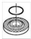
Quick-clamping nut SDS-e/ie
To change the abrasive tool easily without having to use any additional tools, you can use the quick-clamping nut (16) instead of the clamping nut (15).
The quick-clamping nut (16) may be used only for grinding or cutting discs.
Only use quick-clamping nuts (16) that are in good working order and not damaged.
When screwing on, make sure that the printed side of the quick-clamping nut (16) is not facing the grinding disc; the arrow must be pointing towards the index mark (33).
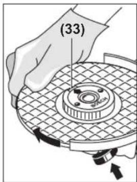
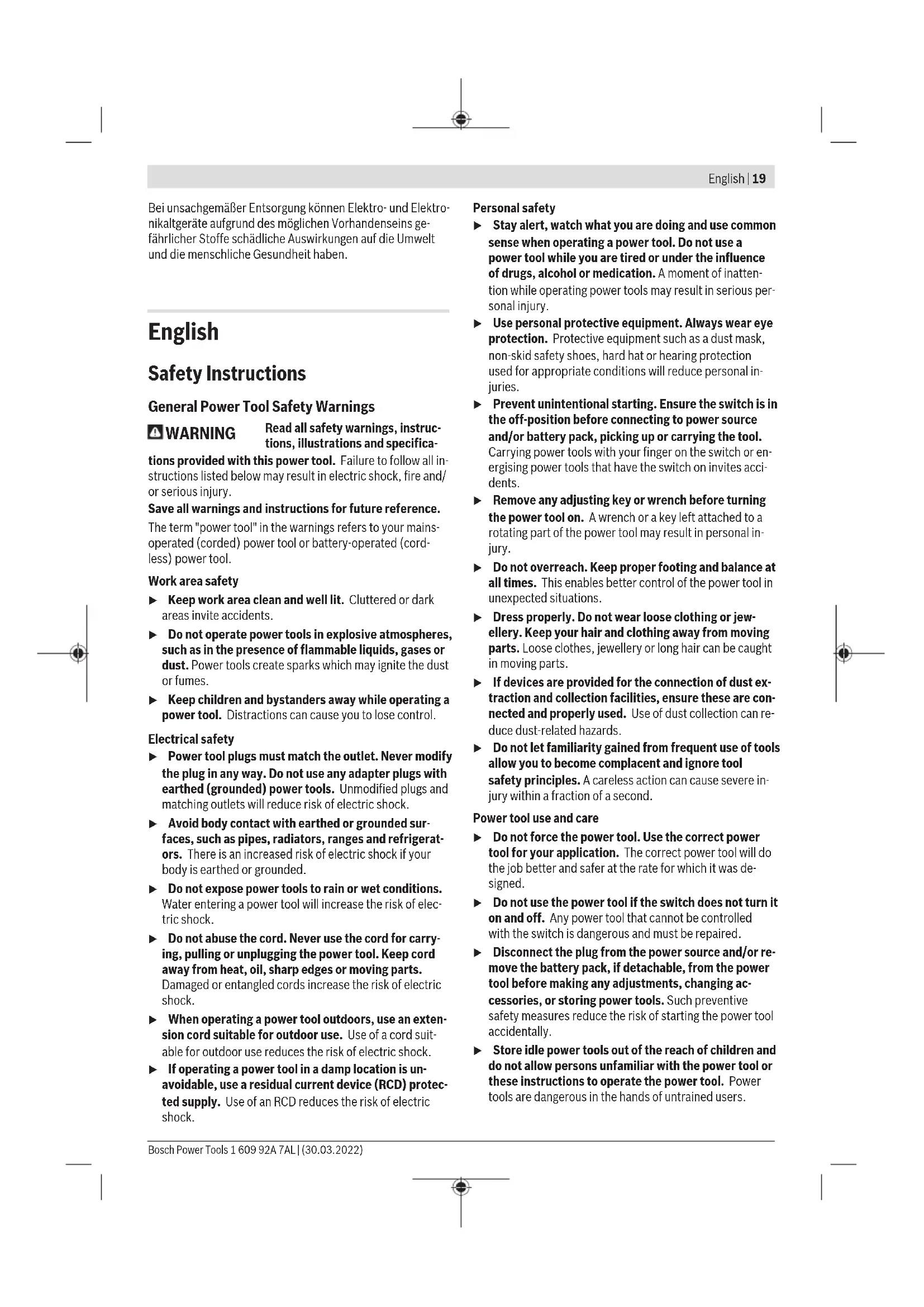
Press the spindle lock button (2) to lock the grinding spindle. To tighten the quick-clamping nut, turn the grinding disc firmly clockwise.
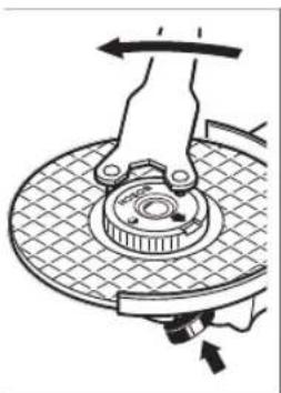
If the quick-clamping nut has been attached correctly and is not damaged, you can loosen it by hand by turning the knurled ring anticlockwise. If the quick-clamping nut is stuck, do not attempt to loosen it with pliers - always use the two-pin spanner. Position the two-pin spanner as shown in the figure.
Approved abrasive tools
You can use all the abrasive tools mentioned in these operat ing instructions.
The permissible speed [^-1] or the circumferential speed [m / s] of the abrasive tools used must at least match the values given in the table.
It is therefore important to observe the permissible rotational/circumferential speed on the label of the abrasive tool.
Max. [mm] [mm]
![BOSCH GWS 15125 CIEP Professional - Max. [mm] [mm] - 1](/content/2026/03/436594/images/17f196eb4b9bc53e254d5a4af77a0761aa8d51456a4eb06022b9f58a69f51a98.jpg)
![BOSCH GWS 15125 CIEP Professional - Max. [mm] [mm] - 2](/content/2026/03/436594/images/78f259bd5715f7610dbd05dc94688ea987e283880ea0e84170209ed7d213c59c.jpg)
Dbsda [min
^-1] [m/s]
![BOSCH GWS 15125 CIEP Professional - ^-1] [m/s] - 1](/content/2026/03/436594/images/bfdb0994fb3a41c76dc6ab88e074b411a94f495fa45457c572a9f0641888bf51.jpg)
1257.2-22.2-11,50080
![BOSCH GWS 15125 CIEP Professional - ^-1] [m/s] - 2](/content/2026/03/436594/images/7b20cf43d295237b573cc00cbd7e521f11c3f56aa6483b28e4161e2ba59f802b.jpg)
1254.2-22.2-11,50080
![BOSCH GWS 15125 CIEP Professional - ^-1] [m/s] - 3](/content/2026/03/436594/images/61787c8cce157ad0762a05d023b31e10ba00a9abaf2c0c05bcc9bf4226527580.jpg)
125- - - - 11,50080
![BOSCH GWS 15125 CIEP Professional - ^-1] [m/s] - 4](/content/2026/03/436594/images/6f39ed3a6b5ce30992fbf2d00fe808502cac6b3f14bd32510dec7214634e486b.jpg)
7530--11,50045
![BOSCH GWS 15125 CIEP Professional - ^-1] [m/s] - 5](/content/2026/03/436594/images/7070565fb29e85045f1518adca966413d0bdf84af7a6bb4ba7181eb76dd0aaaa.jpg)
125 24 - M14 - 11.500 80
125 19 - 22.2 - 9300 80
![BOSCH GWS 15125 CIEP Professional - ^-1] [m/s] - 6](/content/2026/03/436594/images/03111a7bb4eede6aa8b4115e53bc2636118ef6628d48f1f3a0547b149e54fbc2.jpg)
125--M14-11,50080
![BOSCH GWS 15125 CIEP Professional - ^-1] [m/s] - 7](/content/2026/03/436594/images/dadea8a3c54bba9ea7738a3703924396ca7f272c46465a05ec799be9d6212356.jpg)
83--M14-11,50080
![BOSCH GWS 15125 CIEP Professional - ^-1] [m/s] - 8](/content/2026/03/436594/images/9b49cde89c62d4902867d2af70d3a253577c2627eade502655c135ab73e7ef39.jpg)
12561022.2>011,50080
![BOSCH GWS 15125 CIEP Professional - ^-1] [m/s] - 9](/content/2026/03/436594/images/6494148421b1bd2177d56a15e9e238ba761f9fa94f61b86fc1a434dee0837f47.jpg)
125 21-22.2-11,50080
Rotating the machine head (see figure E)
Pull the plug out of the socket before carrying out any work on the power tool.
The machine head can be rotated in 90^ increments. In this way, the on/off switch can be brought into a more favourable handling position for particular applications, e.g. for left-handed tool users.
Completely unscrew the four screws (1). Rotate the machine head carefully, without removing it from the housing, into the new position (2). Screw in and retighten the four screws (3).
Dust/Chip Extraction
The dust from materials such as lead paint, some types of wood, minerals and metal can be harmful to human health. Touching or breathing in this dust can trigger allergic reactions and/or cause respiratory illnesses in the user or in people in the near vicinity.
Certain dusts, such as oak or beech dust, are classified as carcinogenic, especially in conjunction with wood treatment additives (chromate, wood preservative). Materials containing asbestos may only be machined by specialists.
- Use a dust extraction system that is suitable for the material wherever possible.
- Provide good ventilation at the workplace.
- It is advisable to wear a P2 filter class breathing mask.
The regulations on the material being machined that apply in the country of use must be observed.
- Avoid dust accumulation at the workplace. Dust can easily ignite.
Operation
Do not load the power tool so heavily that it comes to a stop.
Pull the plug out of the socket before carrying out any work on the power tool.
Exercise caution when cutting slots in structural walls; see the "Information on structural design" section.
- Clamp the workpiece if it is not secure under its own weight.
If the power tool has been subjected to a heavy load, continue to run it at no-load for several minutes to cool down the accessory.
Do not use the power tool with a cut-off stand.
Do not touch grinding and cutting discs until they have cooled down. The discs can become very hot while working.
Working advice
Rough grinding
Always use the protective guard for grinding (8) when rough grinding with bonded abrasives.
Never use cutting discs for rough grinding.
When rough grinding, the protective guard for cutting (9) or the protective guard for grinding (8) with a fitted cover for cutting (27) can impact the workpiece and lead to a loss of control.
The best rough grinding results are achieved with a set angle of 30^ to 40^ . Move the power tool back and forth with moderate pressure. This will ensure that the workpiece does not become too hot or discolour and that grooves are not formed.
The protective guard for cutting (9) or the protective guard for grinding (8) with a fitted cover for cutting (27) must be used when using bonded discs which are approved for cutting and grinding.
Surface grinding with flap disc
Always use the protective guard for grinding (8) when grinding with the flap disc.
The flap disc (accessory) enables you to machine curved surfaces and profiles. Flap discs have a considerably longer service life, lower noise levels and lower grinding temperatures than conventional grinding discs.
Surface grinding with sanding disc
Always fit the hand guard (21) when working with the rubber sanding pad (22).
Grinding with a sanding disc can be done without a protective guard.
See the graphics page for fitting instructions.
28 | English
Screw on the round nut (24) and tighten it with the two-pin spanner.
Cup brush/disc brush/conical brush
Always use the protective guard for grinding (8) when brushing with disc brushes. Brushing with cup brushes/conical brushes can be performed without the protective guard.
Always fit the hand guard (21) when working with the cup brush or conical brush.
The wires of the disc brush can get caught on the protective guard and break, if the maximum permitted dimensions of the disc brushes are exceeded.
See the graphics page for fitting instructions.
The cup brush/conical brush/disc brush with M14 thread must be screwed onto the grinding spindle until it rests firmly against the grinding spindle flange at the end of the grinding spindle thread. Tighten the cup brush/conical brush/disc brush with an open-ended spanner.
To fasten the disc brush with a diameter of 22.22mm attach the mounting flange with O-ring (10) to the grinding spindle (18), screw on the round nut (24) and tighten with the two-pin spanner.
Cutting Metal
For cutting metal with bonded cutting discs or diamond cutting discs, always use the protective guard for cutting (9) or the protective guard for grinding (8) with a fitted cover for cutting (27).
When using the protective guard for grinding (8) for cutting work with bonded cutting discs, there is an increased risk of being exposed to sparks, particles and disc fragments if the disc breaks.
When carrying out abrasive cutting, use a moderate feed that is suited to the material being machined. Do not exert pressure on the cutting disc and do not tilt or swing the power tool.
Do not attempt to reduce the speed of a cutting disc coming to a stop by applying pressure from the side.
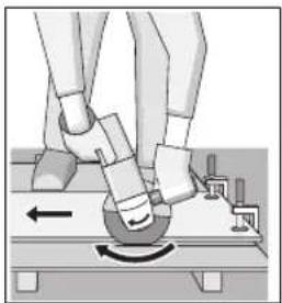
The power tool must always work in an up-grinding motion. Otherwise there is a risk that it will be pushed uncontrolled out of the cut. For best results when cutting profiles and rectangular tubing, start at the smallest cross section.
Cutting stone
For cutting stone with bonded cutting discs or diamond cutting discs for concrete/stone, always use the extraction guard for cutting with a cutting guide (19) or the protective guard for cutting (9) or the protective guard for grinding (8) with a fitted cover for cutting (27).
Provide sufficient dust extraction when cutting stone.
Wear a dust mask.
The power tool may be used only for dry cutting/grinding.
When using the protective guard for cutting (9), the protective guard for grinding (8) or the protective guard for grinding (8) with a fitted cover for cutting (27) for cutting and grinding applications in concrete or masonry, there is an increased dust load and an increased risk of losing control of the power tool, which can lead to kickback.
For cutting stone, it is best to use a diamond cutting disc. When using the extraction guard for cutting with a cutting guide (19), the dust extractor must be approved for extracting stone dust. Suitable dust extractors are available from Bosch.
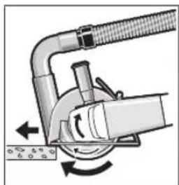
Switch on the power tool and position it with the front part of the cutting guide on the workpiece. Move the power tool with a moderate feed motion that is suited to the material being machined. When cutting especially hard materials such as con
crete with a high pebble content, the diamond cutting disc can overheat and become damaged as a result. This is clearly indicated by circular sparking, rotating with the diamond cutting disc.
If this happens, stop cutting and allow the diamond cutting disc to cool down by running the power tool for a short time at maximum speed with no load.
If work is noticeably slower and with circular sparking, this indicates that the diamond cutting disc has become blunt. You can resharpen the disc by briefly cutting into abrasive material (e.g. lime-sand brick).
Cutting other materials
For cutting materials such as plastic, composite materials, etc. with bonded cutting discs or Carbide Multi Wheel cutting discs, always use the protective guard for cutting (9) or the protective guard for grinding (8) with a fitted cover for cutting (27). You can achieve improved dust extraction by using the extraction guard with a cutting guide (19).
Working with Diamond Annular Cutters
Only use dry diamond annular cutters.
Always fit the hand guard (21) when working with diamond annular cutters.
Do not place the diamond annular cutter parallel to the workpiece. Plunge it into the workpiece at an angle and in a circular motion. This will allow you to achieve optimal cooling and ensure a longer tool life for the diamond annular cutter.
Information on structural design
Recesses in load-bearing walls are subject to country-specific regulations. These regulations must be observed under
all circumstances. Seek advice from the responsible structural engineer, architect or construction supervisor before starting work.
Start-up
When operating the power tool using a mobile generator that does not have sufficient reserve capacity or an adequate voltage control system with inrush current boost converter, loss of performance or atypical behaviour may occur upon switch-on.
Please check the suitability of the power generator you are using, particularly with regard to the mains voltage and frequency.
▶ Products that are only sold in AUS and NZ: Use a residual current device (RCD) with a nominal residual current of 30 mA or less.
Pay attention to the mains voltage. The voltage of the power source must match the voltage specified on the rating plate of the power tool.
Switching On/Off
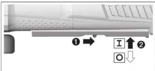
To start the power tool, push the unlocking lever (5) to the rear and then push the on/off switch (3) upwards.
To switch off the power tool, release the on/off switch (3).
Always check abrasive tools before using them. The abrasive tool must be fitted properly and be able to move freely. Carry out a test run for at least one minute with no load. Do not use abrasive tools that are damaged, run untrue or vibrate during use. Damaged abrasive tools can burst apart and cause injuries.
Maintenance and Service
Maintenance and Cleaning
Pull the plug out of the socket before carrying out any work on the power tool.
To ensure safe and efficient operation, always keep the power tool and the ventilation slots clean.
In extreme conditions, always use a dust extractor if possible. Blow out ventilation slots frequently and install a residual current device (RCD) upstream. When machining metals, conductive dust can settle inside the power tool, which can affect its protective insulation.
Store and handle the accessories carefully. In order to avoid safety hazards, if the power supply cord needs to be replaced, this must be done by Bosch or by an
after-sales service centre that is authorised to repair Bosch power tools.
After-Sales Service and Application Service
Our after-sales service responds to your questions concerning maintenance and repair of your product as well as spare parts. You can find explosion drawings and information on spare parts at: www.bosch-pt.com
The Bosch product use advice team will be happy to help you with any questions about our products and their accessories.
In all correspondence and spare parts orders, please always include the 10-digit article number given on the nameplate of the product.
Great Britain
Robert Bosch Ltd. (B.S.C.)
P.O.Box 98
Broadwater Park
North Orbital Road
Denham Uxbridge
UB95HJ
At www.bosch-pt.co.uk you can order spare parts or arrange the collection of a product in need of servicing or repair.
Tel. Service: (0344) 7360109
E-Mail: boschservicecentre@bosch.com
You can find further service addresses at:
www.bosch-pt.com/serviceaddresses
Disposal
The power tool, accessories and packaging should be recycled in an environmentally friendly manner.
Do not dispose of power tools along with household waste.
Only for EU countries:
According to the European Directive 2012/19/EU on Waste Electrical and Electronic Equipment and its implementation into national law, power tools that are no longer usable must be collected separately and disposed of in an environmentally friendly manner.
If disposed incorrectly, waste electrical and electronic equipment may have harmful effects on the environment and human health, due to the potential presence of hazardous substances.
Only for United Kingdom:
According to Waste Electrical and Electronic Equipment Regulations 2013 (2013/3113), power tools that are no longer usable must be collected separately and disposed of in an environmentally friendly manner.