
IPCA72520 - Security alarm ABUS - Free user manual and instructions
Find the device manual for free IPCA72520 ABUS in PDF.
| Product Type | 8-zone radio extension module for alarm system |
| Brand | ABUS |
| Model | IPCA72520 |
| Number of wireless zones | 8 zones for detectors and 8 wireless remote controls |
| Operating frequency | 868.6625 MHz (bandwidth 20 kHz) |
| Transmission power | Max. 10 mW |
| Radio range (open air) | 100 to 200 m |
| Power supply | 12 V DC (via bus or separate power supply) |
| Power consumption | 55 mA max. at 12 V DC |
| Dimensions (H x W x D) | 220 mm x 135 mm x 45 mm |
| Weight | 330 g |
| Operating temperature | -10 °C to 55 °C |
| Maximum humidity | 93 % |
| Display | 2 x 7-segment LED (visible when housing open) |
| LED indicators | "Error" LED (red) and "OK" LED (green) |
| Tamper contact | Yes (with bypass option) |
| Main functions | Learning of detectors and radio remote controls, supervision, jamming detection, low battery indication |
| Compatibility | TERXON L alarm panel and other bus extensions |
| Maximum bus distance | 1 km (with cable 8 x 0.22 mm) |
| Minimum bus supply voltage | 10.5 V DC (12 V recommended) |
| Security | Unique identification code encrypted 16 million times |
| Maintenance and cleaning | Disconnect power before any maintenance. Clean with a dry cloth. |
| Disposal | Do not dispose of with household waste. Recycle according to WEEE Directive 2012/19/EU. |
| Package contents | Radio extension module, mounting base, screws, user manual |
Frequently Asked Questions - IPCA72520 ABUS
For optimal range, avoid obstacles and interference.
User questions about IPCA72520 ABUS
0 question about this device. Answer the ones you know or ask your own.
Ask a new question about this device
Download the instructions for your Security alarm in PDF format for free! Find your manual IPCA72520 - ABUS and take your electronic device back in hand. On this page are published all the documents necessary for the use of your device. IPCA72520 by ABUS.
USER MANUAL IPCA72520 ABUS
natural_image
White rectangular electronic device with glossy surface and small logo (no visible text or symbols)8-Zone Radio Expander
Installation Instructions (UK)....9
Installation Instructions (FR) 16
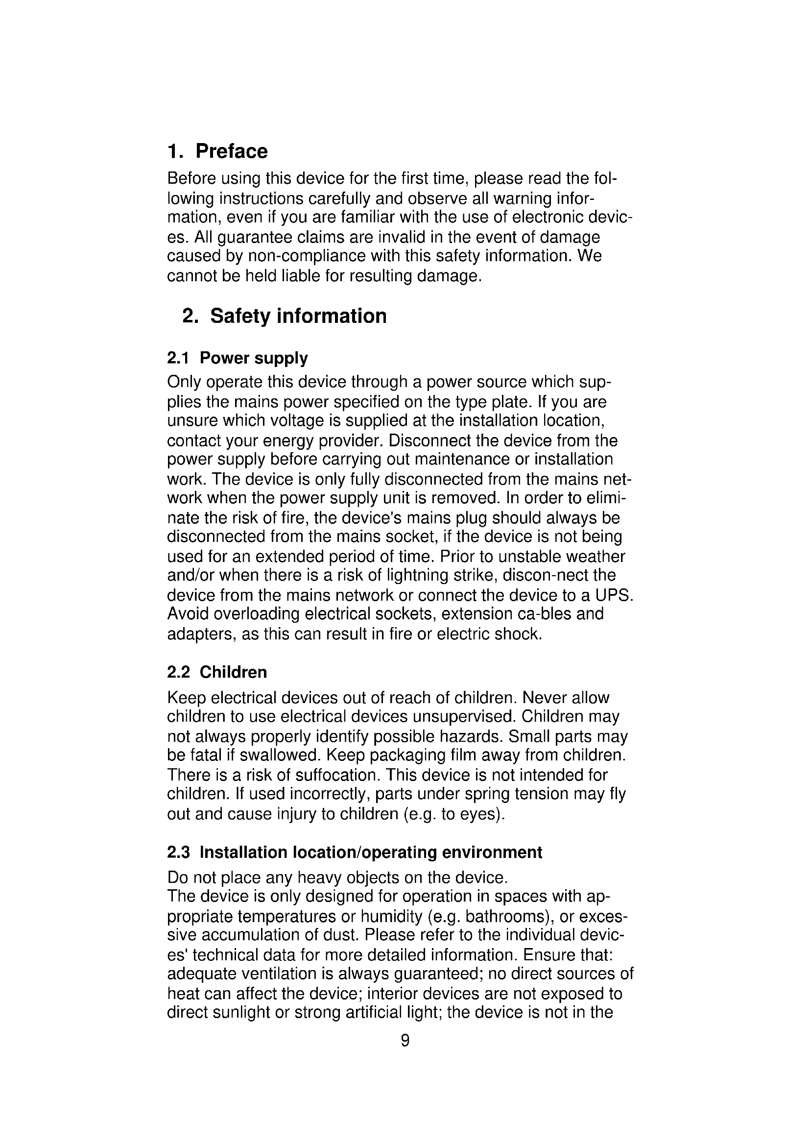
Before using this device for the first time, please read the following instructions carefully and observe all warning information, even if you are familiar with the use of electronic devices. All guarantee claims are invalid in the event of damage caused by non-compliance with this safety information. We cannot be held liable for resulting damage.
2. Safety information
2.1 Power supply
Only operate this device through a power source which supplies the mains power specified on the type plate. If you are unsure which voltage is supplied at the installation location, contact your energy provider. Disconnect the device from the power supply before carrying out maintenance or installation work. The device is only fully disconnected from the mains network when the power supply unit is removed. In order to eliminate the risk of fire, the device's mains plug should always be disconnected from the mains socket, if the device is not being used for an extended period of time. Prior to unstable weather and/or when there is a risk of lightning strike, disconnect the device from the mains network or connect the device to a UPS. Avoid overloading electrical sockets, extension ca-bles and adapters, as this can result in fire or electric shock.
2.2 Children
Keep electrical devices out of reach of children. Never allow children to use electrical devices unsupervised. Children may not always properly identify possible hazards. Small parts may be fatal if swallowed. Keep packaging film away from children. There is a risk of suffocation. This device is not intended for children. If used incorrectly, parts under spring tension may fly out and cause injury to children (e.g. to eyes).
2.3 Installation location/operating environment
Do not place any heavy objects on the device.
The device is only designed for operation in spaces with appropriate temperatures or humidity (e.g. bathrooms), or excessive accumulation of dust. Please refer to the individual devices' technical data for more detailed information. Ensure that: adequate ventilation is always guaranteed; no direct sources of heat can affect the device; interior devices are not exposed to direct sunlight or strong artificial light; the device is not in the
immediate vicinity of magnetic fields (e.g. loudspeakers); no naked flames (e.g. lit candles) are placed on or next to the device; sprayed or dripping water is prevented from coming into contact with interior devices and caustic fluids are avoided; the device is not operated in the vicinity of water, in particular, the device should never be submerged (do not place objects containing fluids, e.g. vases or drinks, on or near the device); no foreign bodies penetrate the device; the device is not ex-posed to wide temperature variations, as otherwise there may be condensation from humidity causing electrical short circuits; the device is not exposed to excessive shock or vibration.
3. Main features
The 8-zone radio extension allows you to train up to 8 radio sensors and radio controls via the integrated antenna.
The radio extension is connected to the alarm centre like the wired extension and works on the Security frequency of 868.66 MHz.
Every radio sensor or other radio device has a special identification code that is learned by the radio extension during installation. Each code is 16 million times encrypted. This ensures that the 8-zone extension reacts only to previously trained components.
The radio devices that work together with the TERXON L have a maximum range of between 100 and 200 m in the open. Remember this range when installing the device.
In some circumstances, you may notice a reduced radio range. This can be caused by various external influences. Particularly inside buildings, the range can be considerably reduced. Depending on the material used, the radio signals are weakened or even completely cut off.
4. Installation
- Disconnect the alarm centre from the power supply (mains and battery).
- Remove the housing screws of the extension module.
- Open the housing of the radio extension.
- If the extension is to be installed at a distance from the alarm centre, use the base as a drilling template. Draw the cables through the base and fix the base to the wall.
- Connect all cables and set the jumpers and switches as described on the next page.
-
Clamp the front plate to the housing and screw it tight.
-
Description of Components
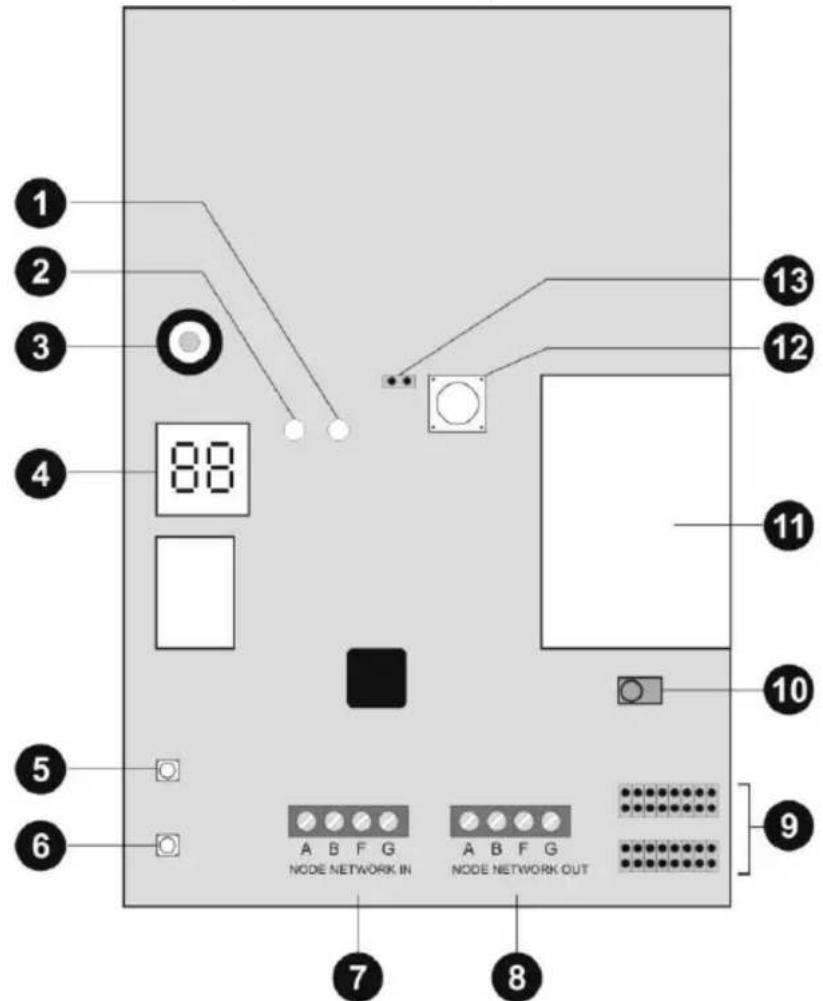
1.) Error-LED
2.) OK-LED
3.) Signalling device
4.) Display
5.) Selection key
6.) Delete key
7.) Bus input
Normally an 8x0.22mm alarm cable is used. Use screened cables in areas with interference frequencies (see also Installation Instructions).
Important: The maximum distance to the furthest extension must not exceed 1 km.
Important: The voltage supply on the operating panels must not fall below 10.5V DC (recommendation: min. 12V). If the voltage is too low, duplicate the voltage leads with remaining cables or use an additional voltage supply.
Before connecting the radio extension, make sure than the alarm centre is disconnected from the power supply. The first extension to the bus is connected to the alarm centre
via the NODE NETWORK IN connector (bus input). Each successive extension is connected to NODE NETWORK OUT (bus output) of the previous extension.
8.) Bus output
9.) Address of the extension
Set the jumper on the right position of the extension module. Please ake care of using different adresses for different extension modules.
10.) Learn sensor
11.) Radio module
12.) Tamper contact
13.) Jumper tamper contact
6. Programming
6.1 Setting learn mode
To put the extension module in learn mode, connect the 12 V DC voltage supply (from the bus or a separate voltage supply). When all sensors have been trained in the radio extension, they are permanently stored, even if the power supply is removed. When the voltage supply is first connected, the display shows "88" and a short double signal sounds.
To enter learn mode, open the tamper contact (remove the front panel) and then press "SELECT". The display now shows "--". The module is now in learn mode.
Important: Before disconnecting the power supply, exit learn mode of the extension module so that you do not lose the trained devices.
6.2 Training radio components
-
Put the extension module in learn mode.
-
Make sure that the LED of the radio component to be instructed is pointing to the learn sensor at a maximum distance of 10 cm.
Activate the radio component (by triggering the tamper contact if necessary).
The LED must be pointing to the learn sensor of the extension module.
The extension module emits a double tone when the radio component has been successfully trained. For trained sensors, the signal strength (max. 9) is shown on the left and the channel number on the right. The channel is assigned automatically. A trained remote
control shows the number of the learned components with the display "t 2" alternating with the signal strength. Important: If radio components cannot be trained, the extension module emits a single tone.
- Repeat steps 2 and 3 to train further radio components. Note that max. 8 radio remote controls can be trained.
6.3 Assigning sensors to zones
-
Put the extension module in learn mode.
-
Press "SELECT" until the desired zone number appears. If the display flashes, the zone is free. If the display is constant, the zone is occupied.
-
Follow steps 2 and 3 from the section "Training radio components".
6.4 Deleting sensors
- Put the extension module in learn mode.
- Press "SELECT" until the desired zone number appears.
- Press "DELETE" for about 4 seconds. A double tone sounds and the display shows "--". The sensor is now deleted Betriebshinweise
6.5 Deleting additional devices
These components cannot be deleted individually. To delete a component, you have to delete all radio remote controls and then retrain the ones you want to keep.
7. Operation
The radio extension module can detect different errors and faults in the radio components and transmit them to the alarm centre.
- Put the extension module in learn mode.
- Press "SELECT" until the desired zone number or radio remote control number appears. Both LEDs on the PCB must be off.
-
Activate the corresponding radio component. The green LED (Pass) shows that the signal strength is sufficient. The red LED (Fail) shows that the signal strength is not sufficient. The display shows the signal strength and the zone number alternatingly.
-
Repeat steps 2 and 3 to display the signal strength again.
7.2 Jamming
A jamming signal is a signal of the same frequency as the radio components that is strong enough to interfere with the radio signal for at least 30 seconds a minute. Set the “Jamming” jumper to activate this function and transmit a corresponding message to the alarm centre.
7.3 Supervision
Set the “Supervision” jumper to activate this function. The radio extension reports a sensor as faulty if it receives no signal from this sensor within the programmed period.
7.4 Sensor low battery
This message is sent to the alarm centre when the battery power of the radio sensor is low.
8. Technical data
| Power consumption | 55 mA max. at 12 V DCDC |
| Zones | 8 radio zones for sensors and up to 8 radio remote controls |
| Display | 2 x 7-segment LED. Visible when case open |
| Transmitter | Frequency: 868.6625 MHzBandwidth: 20 kHz |
| Wireless transmission power | Max. 10 mW |
| Dimensions | 182mm x 128mm x 32mm (HxWxD) |
| Weight | 342g |
| Ambient operating temperature | -10° to 55°C |
| Ambient operating humidity | Max. 93% |
9. Disposal
Important: EU Directive 2012/19/EU regulates the proper return, treatment and recycling of used electronic devices. This symbol means that, in the interest of environmental protection, the device must be disposed of separately from household or industrial waste at the end of its lifespan in accordance with applicable local legal guidelines. Used devices can be disposed of at official
recycling centres in your country. Observe local regulations when disposing of materials. Further details on returns (also for non-EU countries) can be obtained from your local authority. Separate collection and recycling conserve natural resources and ensure that all the provisions for protecting health and the environment are observed when recycling the product.
10. Declaration of conformity
ABUS Security-Center GmbH & Co. KG hereby declares that the wireless unit type with item number AZ4220 complies with Directive 2014/53/EU. The full EU declaration of conformity can be found at: www.abus.com Article search AZ4220/Downloads. The declaration of conformity can also be obtained from the following address:


- 8-Zone Radio Expander
- Safety information
- Power supply
- Children
- Installation location/operating environment
- Main features
- Installation
- 8.) Bus output
- 9.) Address of the extension
- 10.) Learn sensor
- 11.) Radio module
- 12.) Tamper contact
- 13.) Jumper tamper contact
- Programming
- Setting learn mode
- Training radio components
- Assigning sensors to zones
- Deleting sensors
- Deleting additional devices
- Operation
- Jamming
- Supervision
- Sensor low battery
- Technical data
- Disposal
- Declaration of conformity
Brand : ABUS
Model : IPCA72520
Category : Security alarm