
IPCA66500 - Security alarm ABUS - Free user manual and instructions
Find the device manual for free IPCA66500 ABUS in PDF.
| Product Type | 8-zone wired extension module with supplementary PSU |
| Brand | ABUS |
| Model | IPCA66500 |
| Dimensions (H x W x D) | 382 mm x 310 mm x 95 mm |
| Weight | 4.5 kg |
| External Voltage Supply | 230 VAC +/-10%, 50 Hz |
| Internal Voltage Supply | 13.8 V DC |
| Internal Power Supply Output | 1.5 A (750 mA for battery charging) |
| Standby Battery | 12 V DC, 7 Ah or 17 Ah rechargeable |
| Zone Inputs | 8 zones, configurable as NC, FSL (DEOL), or anti-masking |
| Auxiliary Output | 1 output, 12 V DC at 500 mA max, programmable |
| Fuses | 4 auto-resettable fuses (500 mA) + 1 mains fuse (315 mA slow) |
| Bus Interface | Yes, supports up to 1 km total bus length |
| Control Panel Ports | Up to 4 additional panels, max 100 m cable length |
| Loudspeaker Drive | Up to 2 x 16 Ohm speakers in series, volume adjustable |
| Tamper Protection | Tamper switch included (can be disabled via jumper) |
| Operating Temperature Range | -10°C to +55°C |
| Operating Humidity | <96% non-condensing |
| Power Consumption | 60 mA (idle) to 305 mA with loudspeaker at 12 V DC |
| Installation Requirements | Disconnect mains before installation; use separate cable entry for 230V |
| Maintenance | Battery and fuses replaceable; automatic fuses reset after overload |
Frequently Asked Questions - IPCA66500 ABUS
User questions about IPCA66500 ABUS
0 question about this device. Answer the ones you know or ask your own.
Ask a new question about this device
Download the instructions for your Security alarm in PDF format for free! Find your manual IPCA66500 - ABUS and take your electronic device back in hand. On this page are published all the documents necessary for the use of your device. IPCA66500 by ABUS.
USER MANUAL IPCA66500 ABUS
natural_image
Exterior view of a white rectangular electrical enclosure with two mounting holes (no text or symbols)8-zone wired extension with PSU
Installation Instructions (UK)....7
Installation Instructions (NL)....17
Trådudvidelse med 8 zoner med PSU
Installation Instructions (I) 27
1. Merkmale
The 8-zone wired extension with supplementary 1.5 A power supply unit (PSU) enables you to extend the system with 8 wired zones and a programmable output. The emergency power supply is provided by a 7 Ah or 17 Ah rechargeable standby battery. You can connect up to four operating panels to this extension. The extension also permits the connection of 2 additional loudspeakers for acoustic alarm or service signals.
2. Installation
Before installing, make sure that the external voltage supply is disconnected and isolated before making any mains connections.
- Remove the housing screws of the extension module.
- Use the housing as a template to locate the fixing screw holes and drill three holes at these locations (min. 4mm ∅, 4.5 cm long).
- Pull all cables and cores through the base plate and screw the housing firmly to the mounting surface. To prevent interference, pull the 230 V mains cable through a separate opening.
- Connect all cables and set the jumpers and switches as described on the next page.
- Insert the tamper contact in the opening provided.
- Now connect the standby battery and switch on the 230 V mains supply.
- Close the housing with the cover and screw it down.
3. Description of components and programming

1.) Not used
2.) ZONE WIRING
You can connect a detector using one of the following methods. Each zone can be wired differently. The contacts of the detectors are usually NC (normally closed); if you want NO (normally open), program zone with the “Inverted” attribute.
Important: The voltage supply of the detectors is provided by two additional cores for the connections to the AUX terminals (+12 V DC / 0 V).
NC wiring:
Also known as CCL wiring.
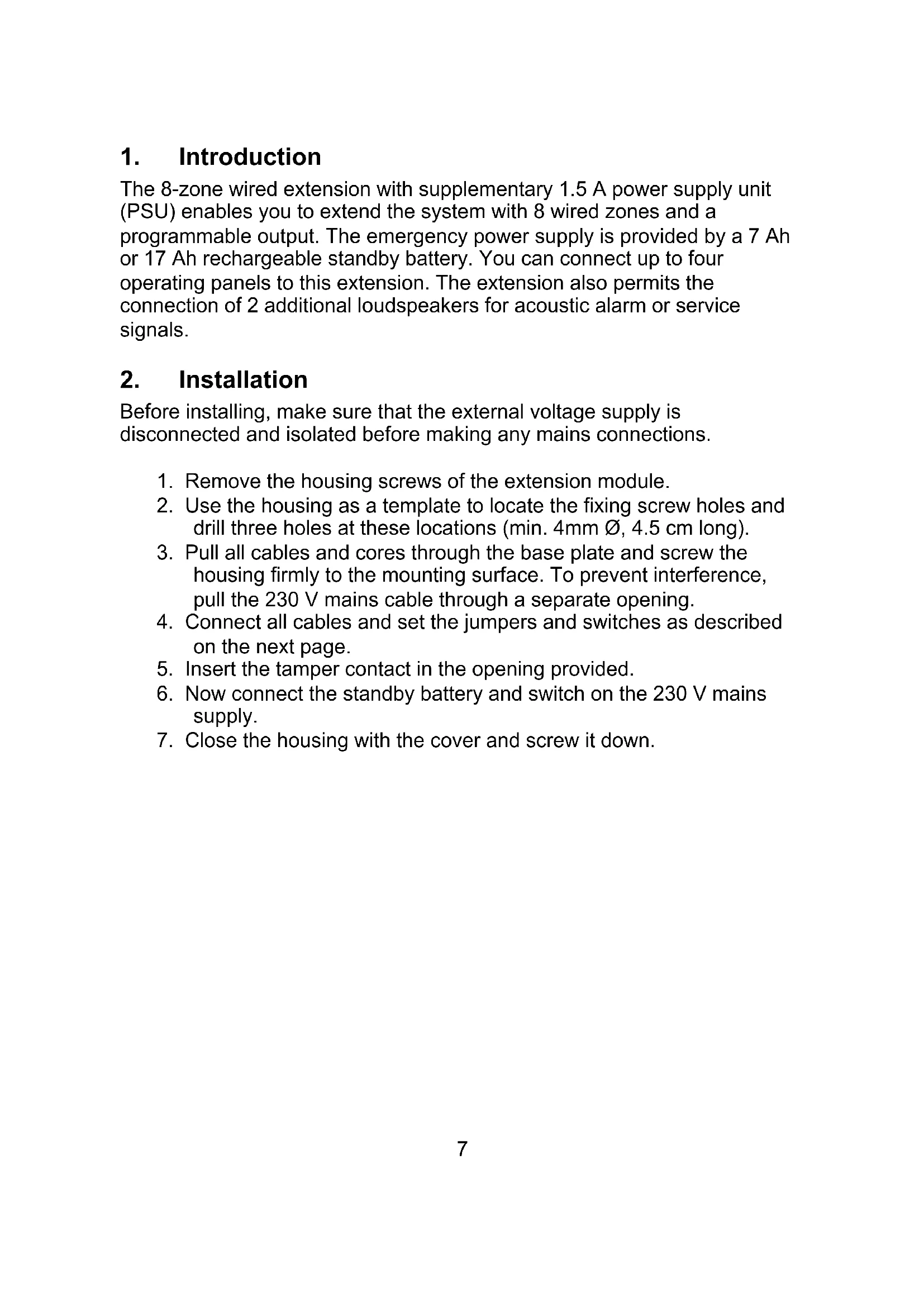
FSL wiring:
Also known as DEOL. Enables individual supervision of a wire tamper
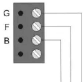
Anti-masking wiring:
If the detector has an anti-mask attribute, three resistors can monitor all states (healthy, alarm, tamper, masked). The zone can be programmed just like any other zone (e.g. Immediately), but must have the
"Masking" attribute.
Important: For wiring examples, see "Installation Instructions AZ5200".
3.) AUX CONNECTOR
Additional terminals to power external detectors and outputs (+12V DC / 0V).
4.) CONNECTION FOR 7AH/17AH STANDBY BATTERY
5.) CONNECTION FOR THE 13.8 V DC VOLTAGE SUPPLY
6.) AUX CONNECTOR
Additional terminals to power external detectors and outputs (+12V DC / 0V).
7.) AUX ERROR LED
Lit when fuse blown.
8.) OUTPUT (OPTIONAL)
By default, the output switches from 0V to 12V (+1) on activation, and can deliver up to 500 mA. The output can be inverted when programming the output. Output -1 must not be used.
9.) CONNECTING LOUDSPEAKERS (OPTIONAL)
Up to 2 external 16 Ohm loudspeakers can be connected in series. The loudspeaker volume can be adjusted by the potentiometer on the PCB.
10.) VOLUME POTENTIOMETER
For adjusting the volume of external loudspeakers.
11.) BUS ERROR LED
Lit when fuse blown.
12.) BUS INPUT
The first extension to the bus is connected to the alarm centre via the NODE NETWORK IN terminal (bus input).
Each successive extension is connected to NODE NETWORK OUT (bus output) of the previous extension.
Important: The maximum distance to the furthest extension must not exceed 1 km.
Important: Do not connect the "A" connector to the 4-core buscable!
13.)BUS OUTPUT
For connecting further extension modules to the bus.
14.) CONNECTING CONTROL PANELS (OPTIONAL)
Up to 4 further control panels can be connected. The maximum distance to the furthest control panel must not exceed 100 m.
Important: The voltage supply on the operating panels must not drop below 10.5V DC (recommendation: min. 12V). If the voltage is too low, double up the cores or use an additional voltage supply.
15.) CONTROL PANEL LED
Lit when fuse blown.
16.)NOT USED
Do not change the DIP switch settings.
17.) ADDRESS OF 8-ZONE WIRED EXTENSION
Set the jumper to the position matching the extension.
Important: Ensure that no two extensions on the same bus have the same address.
18.) TAMPER JUMPER
If the jumper is closed, the tamper contact of the extension module is switched off.
19.)BUS LED
Lit when there is bus communication and flashes when bus communication is lost.
4. Technical data
| External voltage supply 230 VAC | +/- 10%, 50 Hz |
| External power consumption 145 mA | |
| Internal voltage supply 13.8 V DC | |
| Internal power supply 1.5 A (750mA for battery charge) | |
| Internal power consumption | 60 mA max. at 12 V DC;305 mA max. with loudspeaker |
| Standby battery 12 V DC, 7Ah/17Ah battery | |
| Zones | 8 zones; NC or FSL with anti-masking |
| Output 1 output positively switching (+1),500 mA max. at 12V DC | |
| Fuses | 4 fuses (500 mA) automatically resettable; 1 mains fuse (315 mA slow) |
| Dimension 382mm x 310mm x 95mm (HxWxD) | |
| Weight | 4.5 kg |
| Operating temperature -10° to 55°C | |
| Operating humidity Max. 96% | |
1. Introduction


- 8-zone wired extension with PSU
- Trådudvidelse med 8 zoner med PSU
- Merkmale
- Installation
- Description of components and programming
- FSL wiring:
- Anti-masking wiring:
- 3.) AUX CONNECTOR
- 4.) CONNECTION FOR 7AH/17AH STANDBY BATTERY
- 5.) CONNECTION FOR THE 13.8 V DC VOLTAGE SUPPLY
- 6.) AUX CONNECTOR
- 7.) AUX ERROR LED
- 8.) OUTPUT (OPTIONAL)
- 9.) CONNECTING LOUDSPEAKERS (OPTIONAL)
- 10.) VOLUME POTENTIOMETER
- 11.) BUS ERROR LED
- 12.) BUS INPUT
- 13.)BUS OUTPUT
- 14.) CONNECTING CONTROL PANELS (OPTIONAL)
- 15.) CONTROL PANEL LED
- 16.)NOT USED
- 17.) ADDRESS OF 8-ZONE WIRED EXTENSION
- 18.) TAMPER JUMPER
- 19.)BUS LED
- Technical data
- Introduction
Brand : ABUS
Model : IPCA66500
Category : Security alarm