
BFR440 - Screwdriver MAKITA - Free user manual and instructions
Find the device manual for free BFR440 MAKITA in PDF.

| Brand | Makita |
| Model | BFR440 |
| Product type | Collated screwdriver |
| Power supply | 14.4 V lithium-ion battery (not included) |
| No-load speed | 4000 min-1 |
| Total length | 357 mm |
| Net weight | 1.8 kg |
| Screw capacity (strip) | 4 mm x 25-41 mm (length) |
| Screw length adjustment | 3 positions: 25-28 mm, 28-35 mm, 35-41 mm |
| Screw depth adjustment | Yes, via rotary knob |
| Rotation direction switch | Yes, with neutral position |
| Applications | Screwing into wood, metal and plastic |
| Bit supplied | Phillips bit (Makita ref.) |
| Maintenance | Carbon brush replacement, regular cleaning |
| Compatible accessories | Self-drilling screw strips, plastic case, Makita batteries and chargers |
| Safety | Insulated grip surface, neutral position lock, dust protection |
| Sound level | 75 dB(A) (acoustic pressure), uncertainty 3 dB(A) |
| Vibrations | Weighted acceleration < 2.5 m/s² |
| Country of origin | Not specified (manufactured according to European standards) |
Frequently Asked Questions - BFR440 MAKITA
User questions about BFR440 MAKITA
0 question about this device. Answer the ones you know or ask your own.
Ask a new question about this device
Download the instructions for your Screwdriver in PDF format for free! Find your manual BFR440 - MAKITA and take your electronic device back in hand. On this page are published all the documents necessary for the use of your device. BFR440 by MAKITA.
USER MANUAL BFR440 MAKITA
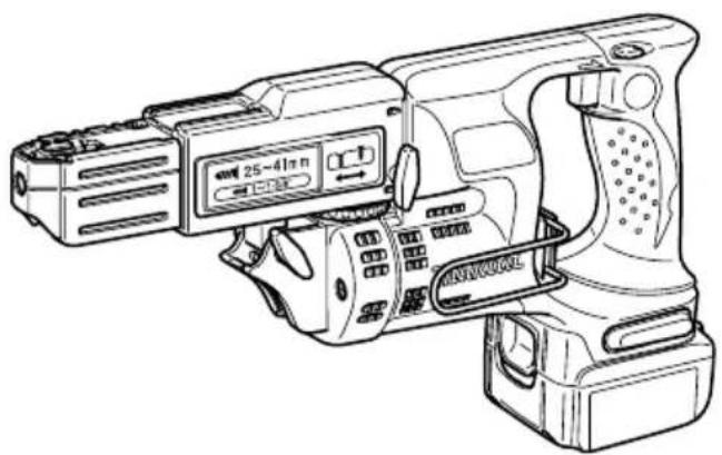
GB Cordless Auto Feed Screwdriver Instruction manual
| F Visseuse à recharge automatique sans fil Manuel d'instructions | |
| D Akku-Magazinschnellschrauber Betriebsanleitung | |
| I Avvitatore a batteria con alimentatore automatico Istruzioni per l'uso | |
| NL Accuschroefautomaat Gebruiksaanwijzing | |
| E Destornillador autoalimentado inalámbrico Manual de instrucciones | |
| P Chave de parafusos sem fios de alimentação automática Manual de instruções | |
| DK Ledningsfri skruetrækker med automatisk fremføring Brugsanvisning | |
| S Sladdlós skruvdragare med automatisk matning | Bruksanvisning |
| N Batteridrevet skrutrekker med automatisk tilførsel | Bruksanvisning |
| SF Johdoton makasiini-ruuvinvännin | Käytöohje |
| GR Φρητό αυτοροφόθοτουμενο κατσαβίδι | Οδηνίες χρήσης |
BFR440
1
2
3
4

5
6
7
8
9
10
11 12
13 14
15 16
17 18
19 20
ENGLISH
Explanation of general view
| 1. | Red part | 11. Thumb screws | 21. Wall |
| 2. | Button | 12. Bit | 22. Limit mark |
| 3. | Battery cartridge | 13. Dust cover | 23. Front cover |
| 4. | Lever | 14. Plane bearing | 24. Screws |
| 5. | Stopper base | 15. Feeder box | 25. Spring |
| 6. | Plate | 16. Screw strip | 26. Arm |
| 7. | Casing | 17. Screw guide | 27. Recessed part |
| 8. | Adjusting knob | 18. Driving position | 28. Carbon brush cap |
| 9. | Switch trigger | 19. Reverse button | |
| 10. | Reversing switch lever | 20. Hook |
SPECIFICATIONS
| Model BFR440 | |
| Screw strip 4 mm x 25 mm - 41 mm | |
| No load speed (min-1) 4,000 | |
| Overall length | 357 mm |
| Net weight | 1.8 kg |
| Rated voltage | D.C. 14.4 V |
- Due to our continuing program of research and development, the specifications herein are subject to change without notice.
- Note: Specifications may differ from country to country.
Intended use
The tool is intended for screw driving in wood, metal and plastic.
ADDITIONAL SAFETY RULES FOR TOOL ENB026-1
- Be aware that this tool is always in an operating condition, because it does not have to be plugged into an electrical outlet.
- Hold tool by insulated gripping surfaces when performing an operation where the cutting tool may contact hidden wiring. Contact with a "live" wire will also make exposed metal parts of the tool "live" and shock the operator.
- Always be sure you have a firm footing. Be sure no one is below when using the tool in high locations.
- Hold the tool firmly.
- Keep hands away from rotating parts.
SAVE THESE INSTRUCTIONS
IMPORTANT SAFETY INSTRUCTIONS FOR BATTERY CARTRIDGE ENC007-1
- Before using battery cartridge, read all instructions and cautionary markings on (1) battery charger, (2) battery, and (3) product using battery.
-
Do not disassemble battery cartridge.
-
If operating time has become excessively shorter, stop operating immediately. It may result in a risk of overheating, possible burns and even an explosion.
- If electrolyte gets into your eyes, rinse them out with clear water and seek medical attention right away. It may result in loss of your eyesight.
- Do not short the battery cartridge:
(1) Do not touch the terminals with any conductive material.
(2) Avoid storing battery cartridge in a container with other metal objects such as nails, coins, etc.
(3) Do not expose battery cartridge to water or rain. A battery short can cause a large current flow, overheating, possible burns and even a breakdown.
- Do not store the tool and battery cartridge in locations where the temperature may reach or exceed 50^ (122^) .
- Do not incinerate the battery cartridge even if it is severely damaged or is completely worn out. The battery cartridge can explode in a fire.
- Be careful not to drop or strike battery.
SAVE THESE INSTRUCTIONS
Tips for maintaining maximum battery life
-
Charge the battery cartridge before completely discharged. Always stop tool operation and charge the battery cartridge when you notice less tool power.
-
Never recharge a fully charged battery cartridge. Overcharging shortens the battery service life.
- Charge the battery cartridge with room temperature at 10^ - 40^ (50^ - 104^) . Let a hot battery cartridge cool down before charging it.
FUNCTIONAL DESCRIPTION
CAUTION:
- Always be sure that the tool is switched off and the battery cartridge is removed before adjusting or checking function on the tool.
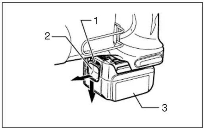
Installing or removing battery cartridge (Fig. 1)
- Always switch off the tool before insertion or removal of the battery cartridge.
- To remove the battery cartridge, withdraw it from the tool while sliding the button on the front of the cartridge.
- To insert the battery cartridge, align the tongue on the battery cartridge with the groove in the housing and slip it into place. Always insert it all the way until it locks in place with a little click. If you can see the red part on the upper side of the button, it is not locked completely. Insert it fully until the red part cannot be seen. If not, it may accidentally fall out of the tool, causing injury to you or someone around you.
- Do not use force when inserting the battery cartridge. If the cartridge does not slide in easily, it is not being inserted correctly.
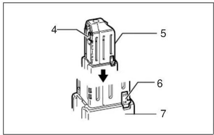
Setting for desired screw length (Fig. 2)
There are 3 positive-lock screw length settings. To obtain the desired setting, pull out the stopper base while depressing the lever until you see the number of the desired screw length (indicated on the plate) appear to rest on the very top edge of the casing.
See the table below for the relation between the number indicated on the plate and the respective screw length ranges.
| Number indicated on the plate | Screw length range (mm) |
| 25/28 | 25 |
| 32 | 28 |
| 41 35 - 41 |
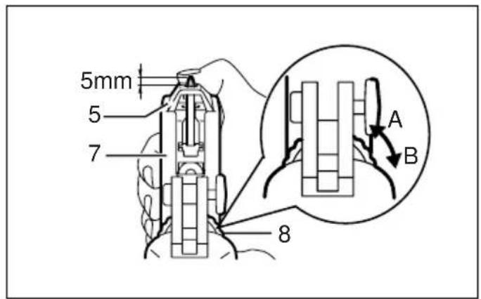
Adjusting the driving depth (Fig. 3)
Depress the stopper base as far as it will go. While keeping it in this position, turn the adjusting knob until the bit tip projects approx. 5mm from the stopper base. Drive a trial screw. If the screw head projects above the driving surface, turn the adjusting knob in the A direction; if the screw head is countersunk, turn the adjusting knob in the B direction.
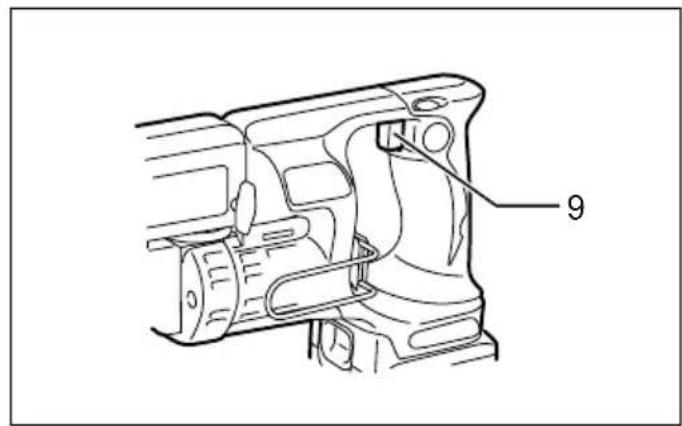
Switch action (Fig. 4)
CAUTION:
- Before inserting the battery cartridge into the tool, always check to see that the switch trigger actuates
properly and returns to the "OFF" position when released.
To start the tool, simply pull the switch trigger. Release the switch trigger to stop.
Reversing switch action (Fig. 5)
This tool has a reversing switch to change the direction of rotation. Depress the reversing switch lever from the A side for clockwise rotation or from the B side for counterclockwise rotation.
When the reversing switch lever is in the neutral position, the switch trigger cannot be pulled.
CAUTION:
- Always check the direction of rotation before operation.
- Use the reversing switch only after the tool comes to a complete stop. Changing the direction of rotation before the tool stops may damage the tool.
- When not operating the tool, always set the reversing switch lever to the neutral position.
ASSEMBLY
CAUTION:
- Always be sure that the tool is switched off and the battery cartridge is removed before carrying out any work on the tool.
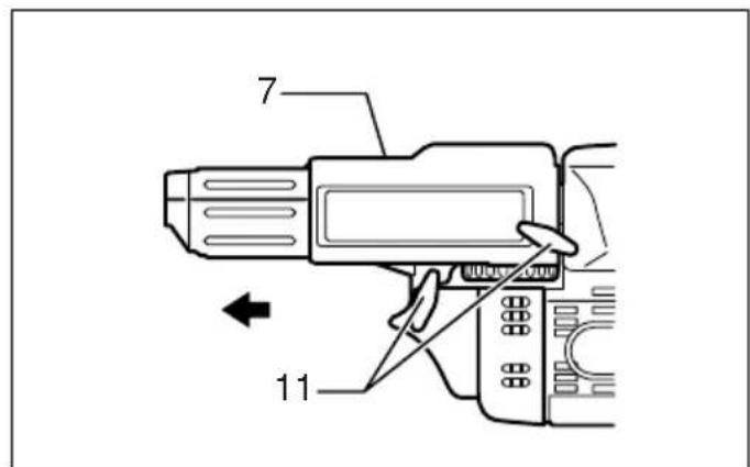
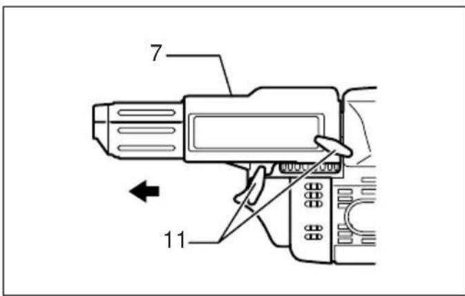
Installing or removing the bit
Loosen the thumb screws which secure the casing. Pull out the casing in the direction of the arrow. (Fig. 6)
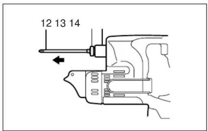
Press the dust cover toward the plane bearing and pull out the bit. If the dust cover cannot be moved as far as the plane bearing, try it again after turning the bit slightly.
To install the bit, insert it into the socket while turning it slightly. After installing, always make sure that the bit is securely held in place by trying to pull it out. (Fig. 7)
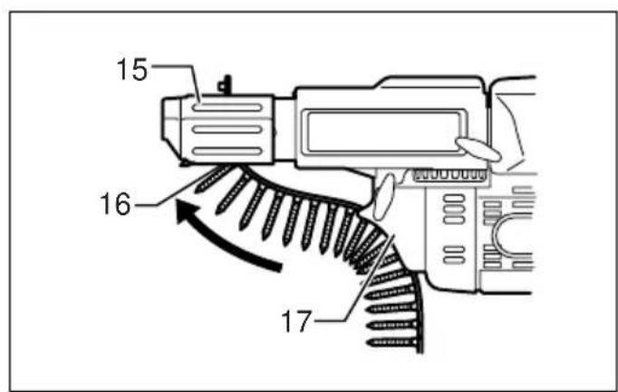
Installing screw strip (Fig. 8 & 9)
Insert the screw strip through the screw guide. Then insert it through the feeder box until the first screw reaches the position next to the driving position.
Removing screw strip
To remove the screw strip, just pull it out in the direction of the arrow. (Fig. 10)
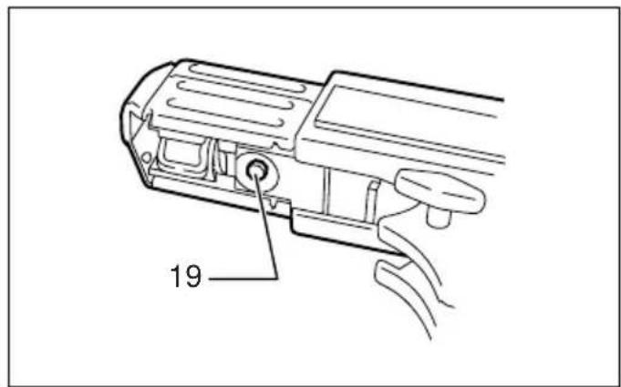
If you depress the reverse button, you can pull out the screw strip in the reverse direction of the arrow. (Fig. 11)
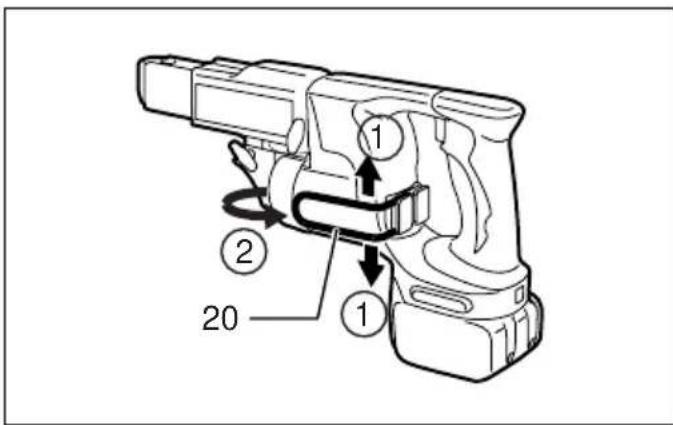
Carry hook (Fig. 12)
The carry hook is convenient for temporarily hooking the tool. It can be installed on either side of the tool.
When removing the carry hook, widen it by pressing its right ends ON BOTH SIDES in the directions of arrow (1) and raise it in the direction of the arrow (2).
OPERATION
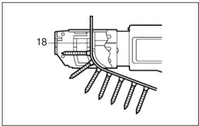
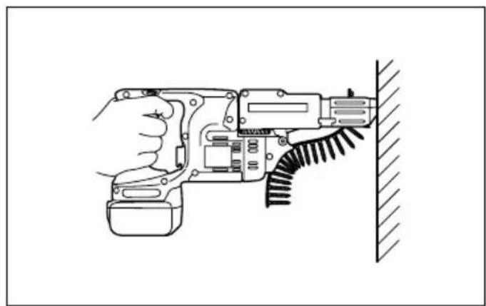
Driving operation (Fig. 13)
Switch on the tool by pulling the switch trigger. Hold the tool squarely and firmly up against the driving surface. A
screw will be automatically carried to the driving position and fastened.
CAUTION:
- Always check the bit carefully for wear before driving operations. Replace a worn bit or poor fastening may result.
- Always hold the tool squarely against the driving surface. Holding it at an angle may damage the screw heads and cause wear on the bit. This may also lead to poor fastening.
- Always keep the tool firmly against the driving surface until the driving is over. Failure to do so may cause insufficient fastening of screws.
- Be careful not to drive a screw onto another screw already fastened.
- Do not operate the tool without screws. It will damage the driving surface.
- If the feeder box does not work smoothly when driving screws, spray car wax (spray type) on the sliding surfaces. Never lubricate it.
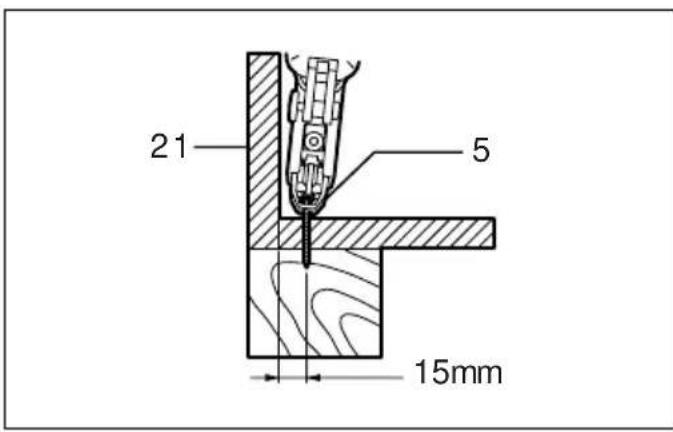
Driving in corner (Fig. 14)
This tool can be used to drive at a position 15mm away from the wall as shown in the figure.
CAUTION:
- Driving at a position closer than 15mm to the wall or driving with the stopper base in contact with the wall may damage the screw heads and cause wear on the bit. This may also lead to poor fastening of screws and malfunction of the tool.
MAINTENANCE
CAUTION:
- Always be sure that the tool is switched off and the battery cartridge is removed before attempting to perform inspection or maintenance.
Replacing carbon brushes
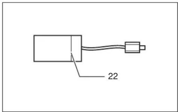
Replace when they wear down to the limit mark. Keep the carbon brushes clean and free to slip in the holders. Both carbon brushes should be replaced at the same time. Use only identical carbon brushes. (Fig. 15)
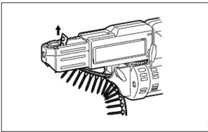
Loosen the thumb screws which secure the casing. Pull out the casing in the direction of the arrow. (Fig. 16)
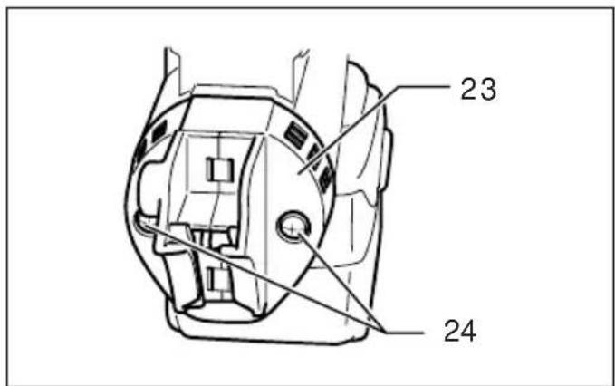
Use a screwdriver to remove two screws then remove the front cover. (Fig. 17)
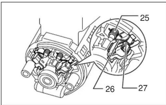
Raise the arm part of the spring and then place it in the recessed part of the housing with a slotted bit screwdriver of slender shaft or the like. (Fig. 18)
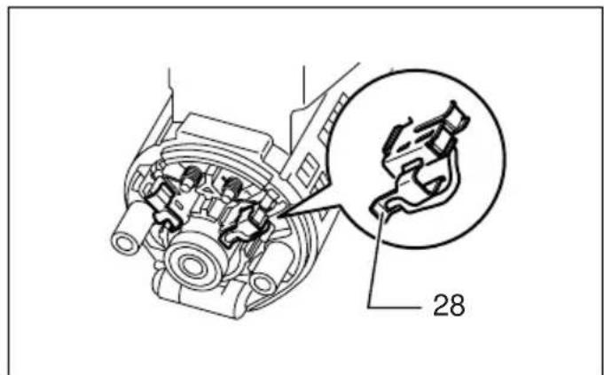
Use pliers to remove the carbon brush caps of the carbon brushes. Take out the worn carbon brushes, insert the new ones and replace the carbon brush caps in reverse.
(Fig. 19)
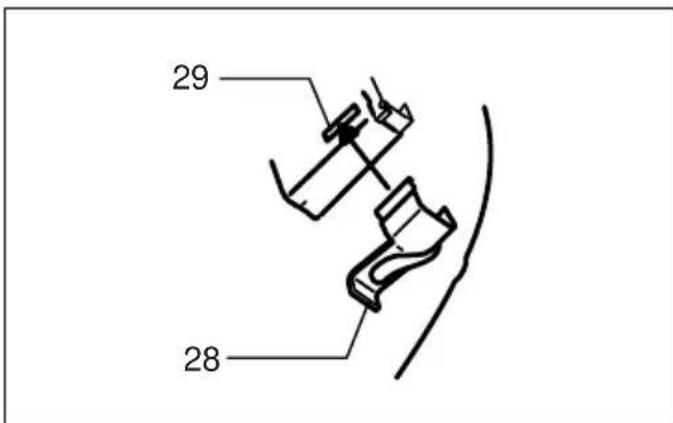
Make sure that the carbon brush caps have fit into the holes in brush holders securely. (Fig. 20)
Reinstall the front cover and tighten two screws securely.
To maintain product SAFETY and RELIABILITY, repairs, any other maintenance or adjustment should be per
formed by Makita Authorized Service Centers, always using Makita replacement parts.
ACCESSORIES
CAUTION:
- These accessories or attachments are recommended for use with your Makita tool specified in this manual. The use of any other accessories or attachments might present a risk of injury to persons. Only use accessory or attachment for its stated purpose.
If you need any assistance for more details regarding these accessories, ask your local Makita Service Center.
- Drywall screw strip
Phillips bit - Plastic carrying case
- Various type of Makita genuine batteries and chargers
FRANÇAIS
Descriptif
Justere innskruingsdybden (Fig. 3)
Trykk inn stopperfoten sa langt den gär. Mens du holder den i dette stillingen, ma du dreie justeringsknappen til spissen av bitset stikker ca. 5 mm ut fra stopperen. Skruinn en proveskrue. Hvis skruehodet stikker opp over
overflaten, mà du dreie justeringsknappen i A-retningen;
hvis skruehedet blir liggende lavere enn overflaten, mà du dreie justeringsknappen i B-retningen.
EC-DECLARATION OF CONFORMITY
We declare under our sole responsibility that this product is in compliance with the following standards of standardized documents, EN60745, EN55014 in accordance with Council Directives, 89/336/EEC, 98/37/EC.
FRANÇAIS
DECLARATION DE CONFORMITE CE
Michigan Drive, Tongwell, Milton Keynes,
Bucks MK15 8JD, ENGLAND
Responsible manufacturer: Produttore responsable:
EU-DEKLARATION OM KONFORMITET
Michigan Drive, Tongwell, Milton Keynes,
Bucks MK15 8JD, ENGLAND
For European countries only Noise and Vibration
The typical A-weighted sound pressure level is 75dB (A). Uncertainty is 3 dB (A).
The noise level under working may exceed 85 dB (A).
Wear ear protection.-
The typical weighted root mean square acceleration value is not more than 2.5m / s^2
These values have been obtained according to EN60745.
FRANÇAIS
De afwijking is 3 dB (A).
Michigan Drive, Tongwell, Milton Keynes,
Bucks MK15 8JD, ENGLAND
Responsible manufacturer: Produttore responsable:
Michigan Drive, Tongwell, Milton Keynes,
Bucks MK15 8JD, ENGLAND