IR Control 10 - Remote control MARMITEK - Free user manual and instructions
Find the device manual for free IR Control 10 MARMITEK in PDF.
Frequently Asked Questions - IR Control 10 MARMITEK
User questions about IR Control 10 MARMITEK
0 question about this device. Answer the ones you know or ask your own.
Ask a new question about this device
Download the instructions for your Remote control in PDF format for free! Find your manual IR Control 10 - MARMITEK and take your electronic device back in hand. On this page are published all the documents necessary for the use of your device. IR Control 10 by MARMITEK.
USER MANUAL IR Control 10 MARMITEK
1 Table of contents 3
2 Safety instructions. 4
3 Your product 5
3.1 Introduction 5
3.2 Package contents 5
4 Getting started 5
4.1 How it works 5
4.2 Connections 6
4.2.1 IR Input 6
4.2.2 POWER Input 6
4.2.3 IR Output 6
4.3 Installation 6
4.3.1 Locating the IR Receiver 6
4.3.2 Installation of the IR extension cable with emitter LEDs 7
4.3.3 Locating the IR Module 7
4.3.4 Connecting the IR Module 7
4.3.5 Perform a function test of the product 8
4.4 Advanced installation 8
4.4.1 Connecting multiple IR receivers 8
4.4.2 Extend the cable length of the IR receiver 8
5 Frequently asked questions (FAQs) 9
6 Technical specifications 10
7 Optional 11
8 Notification 11
8.1 Declaration of Conformity 11
8.2 Recycling 12
8.3 Copyrights 12
2 Safety instructions
Please read these instructions thoroughly before you use the device and keep them for future reference.
- Only for indoor use.
- Do not use the product in a damp environment or near water.
- Do not expose the product to extremely high or low temperatures, strong light sources or direct sunlight.
- This product is not a toy. Keep out of reach of children.
- Connect the adapter to the mains only after you have verified that the line voltage corresponds to the value specified on the type plates.
- Never connect a power adapter if it's damaged. In such cases, please contact your supplier.
- Disconnect the AC/DC power adapter from the mains when this device is not in use for prolonged time.
- Never open the product: the device may contain parts with deadly voltage.
- Repairs or service should only be performed by qualified personnel.
- Improper use, self-installed modifications or repairs will void any and all warranties.
Marmitek does not accept any product responsibility for incorrect use of the product or use other than for which the product is intended.
Marmitek does not accept liability for any consequential damage other than the legal product responsibility.
3 Your product
3.1 Introduction
Congratulations on your purchase of the IR Control 10^TM . With it you can extend the IR (infrared) signals of remote controls. The IR Control 10^TM makes it possible to operate A/V devices while these are in a closed cupboard or when your A/V equipment is out of sight.
3.2 Package contents
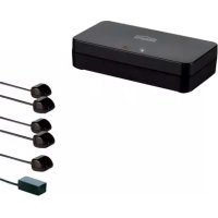
1 x IR Module
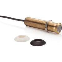
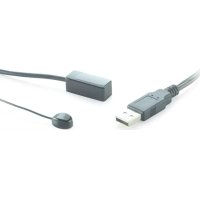
1 x IR Receiver
2 x IR Extension cable with two IR emitter LEDs
1 x Power adaptor
1 x Manual
4 Getting started
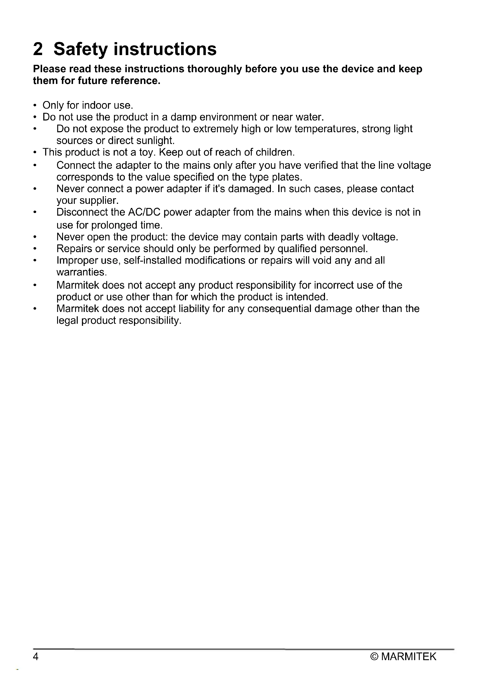
4.1 How it works
Locate your A/V equipment in a closed cupboard, TV cabinet or even in another room. The IR receiver must be installed in view of your own remote control. Stick the IR LEDs on your A/V equipment and conceals the IR main module neatly. Point the remote control at the IR receiver in order to send the appropriate command to the IR LEDs (via the IR main module). These will then immediately pass this onto the A/V equipment.
The IR Control 10^TM is made up of three main components;
1. IR Receiver
The IR Receiver receives infrared commands from your remote control and sends these onto the IR Module.
2. IR Module
The IR Module receives infrared commands from the IR Receiver, processes them and sends them onto all connected IR Extender Cables.
3. IR extension cable with two emitter LEDs
The IR extension cable receives the infrared commands from the IR Module and converts them via the IR LEDs into infrared signals. The IR emitter LEDs have a limited range and therefore they have to be stuck accurately on the IR receiver window of the A/V device you want to operate.
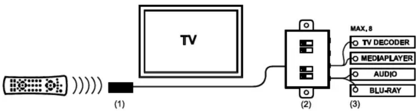
4.2 Connections
The IR Module is the main component that connects IR Receivers, the power adapter and IR Extender Cables to one another. All of the IR Module connections are now explained so that you can get the most out of all of the options available.
4.2.1 IR Input
IR RCVR: standard IR input (3.5mm jack) for the enclosed IR Receiver
SCREW TERMINAL: IR input for connecting up to 6 IR Receivers in parallel.
+12VDC: Red
GND: Black
STATUS: Yellow
IR DATA: White
4.2.2 POWER Input
12VDC: Power adapter for the IR Module (enclosed), 5VDC/200mA
STATUS: Power adapter for the status signal (not enclosed), 5-24VDC or 5-12VAC
4.2.3 IR Output
1 - 4: four mini jack outputs for connecting the IR extension cables.
EMITTER / BLASTER: every output can be switched separately for connecting blaster or emitter LEDs.
4.3 Installation
In order to check that the system works correctly, it is advisable to first test the set-up you had in mind. To do so, connect everything as described below but do not stick the components securely.
4.3.1 Locating the IR Receiver
Place the very small IR Receiver in a way that it is visible for your (infrared) remote control and it can receive the sent commands (max. 10 meters).
- The most logical location for the IR receiver is, for example, on the cabinet in which the A/V equipment is located or near the TV.
- You can run the cable underneath or behind, using the notch at the back of the IR receiver housing; this allows the cable to be hidden easily.
Use the self-adhesive strip which is supplied to locate the IR receiver just about anywhere you please.
Experiment with the location before you stick the IR receiver in its final position.
Note! The sticky strip may lead to discolouration or leave glue residues on certain surfaces.
4.3.2 Installation of the IR extension cable with emitter LEDs
Place the LEDs from the IR extender cable precisely on the IR window (infrared sensor) on the A/V equipment that you wish to operate.
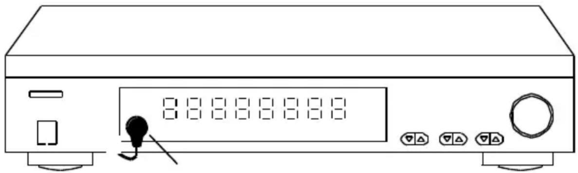
- Ensure that the IR extender cable's LEDs are stuck precisely on the A/V device's infrared sensor (this can be extremely accurate on some devices). The exact position can easily be located by shining a torch on the front panel and looking for the IR sensor window.
All IR LEDs include self-adhesive film with which they are attached to your A/V equipment. - Test the position and the performance of the IR LEDs before you secure them to the IR window on your A/V equipment.
If you use only one of the two LED's, leave the other IR LED unused. Never remove it from the extension cable!
4.3.3 Locating the IR Module
Mount the IR Module at an accessible place behind or alongside your A/V equipment, in the vicinity of an electrical socket.
- Be aware of the cable length of the IR LEDs and the IR receiver.
Make sure the connections for installation remain accessible.
4.3.4 Connecting the IR Module
- Connect the installed IR extension cables to the 'IR OUT' connector of the IR Module.
- Switch only the switches of the IR Module in BLASTER mode if an IR extension cable with one blaster LED is connected. In any other case, leave the switch in the EMITTER mode. NOTE: a wrong choice between the two possibilities can cause damage to the IR LEDs and they can even become defective.
- Connect the installed IR receiver cable to the 'IR RCVR' connector of the IR Module.
- Connect the power adapter to the '12VDC' connector of the IR Module and connect it to the mains.
4.3.5 Perform a function test of the product
- If the IR Control 10 XTRA™ is properly connected, the light on the IR receiver flashes if you push a button on the (infrared) remote control and aim it towards the IR receiver.
- Close the doors of your cabinet and make sure the A/V equipment cannot receive an infrared command directly from the remote control. Otherwise this could lead to operating problems.
- You can now operate your A/V equipment via the IR Control 10 XTRA™ through the closed cabinet doors!
If the IR Control 10 XTRA is not reacting in a correct way, try experimenting with the placement of the IR receiver and/or IR extension cables (emitter or blaster). Placing it somewhere else could give a better result.
4.4 Advanced installation
4.4.1 Connecting multiple IR receivers
If you want to operate your A/V equipment from multiple rooms, you can connect up to 6 IR receivers in parallel to the IR module. Cut therefore the standard connector of the IR receiver and connect it to the SCREW TERMINAL of the IR module (see paragraph 4.1).
4.4.2 Extend the cable length of the IR receiver
Only the cables between the IR receiver and the IR module can be extended. The IR cables with emitter or blaster LEDs cannot be extended. Place the IR module as close as possible to your AV equipment and extend the cable between the IR receiver and the IR module if needed to a maximum of 300 meters with CAT5 cable (or equal). Cut the standard 3.5mm connector off the IR receiver cable and extend the cable according to the example below.
| IR receiver | CAT5 cable | IR module |
| Red | Orange | +12VDC |
| Black | Blue | GND |
| Yellow | Green | STATUS |
| White | Brown | IR DATA |
5 Frequently asked questions (FAQs)
The A/V equipment does not respond to signals from my remote control.
- The IR receiver has a receiving sensitivity of about 10 metres with an acceptance angle of 90 degrees. Range is also dependent on the remote control used.
- If the 'IR data' light on the IR Receiver is continuously illuminated, the IR receiver is probably being disrupted by another infrared signal. Try to locate the IR receiver so that it encounters as little disruption as possible from, for example, direct sunlight, Flat Screen TVs, (LCD, Plasma, LED), fluorescent lighting or energy-efficient light bulbs.
- The IR receiver works with all standard (infrared) remote controls. The only exception (known to us) is Bang & Olufsen (B&O).
- Ensure that the IR receiver and the IR extender cable are correctly connected and that these are plugged in properly.
- Some IR windows from set-top and satellite boxes are very sensitive and are easily disrupted. These devices then receive too much infrared light and will either work badly or not work at all. Relocate the IR LED so that less infrared light is received via the IR window.
Do you have other questions that have not been resolved by the above information?
Please go to www.marmitek.com
6 Technical specifications
IR receiver
Frequency range: 30-60 KHz
IR reception range: ± 10 meters
IR reception angle: 90^ (+45^ / - 45^ from centre
3 meters, extendable up to 300 meters
IR reception indication: YES, purple indication LED
Status indication: YES, green indication LED
Receiver dimensions: 40 × 13 × 11mm
IR module
Power supply POWER: 100-240VAC 50/60Hz, 12VDC 200mA (supplied)
Power supply STATUS: 5-24VDC / 5-12VAC plug, - 5.5mm outside / + 2.1mm inside (not supplied)
IR input: 1x 3.5mm jack connector, for standard IR receiver
1x screw connector, for up to 6 in parallel connected IR receivers. Extendable up to 300 meters using CAT5 (or equivalent)
IR output: 4x 3.5mm jack plug (mono), switchable for IR extension
cables with emitter or blaster LEDs
Dimensions: 95 × 46 × 20mm
IR extension cable with 2 emitter LEDs
Connection: 3.5mm jack plug (mono)
IR LEDs: 2x IR emitter LEDs
Cable length: 3 meters
Specifications may change without prior notice.
7 Optional
Extra IR receiver (Art. nr. 08142)
Every system needs at least one IR receiver (up to 6). With an extra IR receiver you can also operate your A/V devices from another room. See datasheets of the IR receivers at www.marmitek.com
IR extension cable with one blaster LED (Art. nr. 08144)
An IR blaster radiates much more infrared light (even up to 2 meters) so it can operate multiple devices. Placement of the IR blaster is a lot less critical as opposed to IR LEDs. See datasheets of the IR Blaster LED on www.marmitek.com.
IR extension cable with two emitter LEDs (Art. nr. 08145)
The LEDs of the IR extension cables with 2 emitter LEDs have to be stuck to the A/V device(s) you want to operate. See datasheets of the IR emitter LEDs on www.marmitek.com.
8 Notification
8.1 Declaration of Conformity

Hereby, Marmitek BV declares that this IR Control 10^TM is in compliance with the essential requirements and other relevant provisions of the following Directives:
Directive 2014/30/EU of the European Parliament and of the Council of 26 February 2014 on the harmonisation of the laws of the Member States relating to electromagnetic compatibility (recast)
Directive 2014/35/EU of the European Parliament and of the Council of 26 February 2014 on the harmonisation of the laws of the Member States relating to the making available on the market of electrical equipment designed for use within certain voltage limits.
Directive (EU) 2017/2102 of the European Parliament and of the Council of 15 November 2017 amending Directive 2011/65/EU on the restriction of the use of certain hazardous substances in electrical and electronic equipment.
Commission Regulation (EU) 2019/1782 of 1 October 2019 laying down Ecodesign requirements for external power supplies pursuant to Directive 2009/125/EC of the European Parliament and of the Council and repealing Commission Regulation (EC) No 278/2009.
You can read the full Declaration of Conformity at http://www.marmitek.com
8.2 Recycling
Environmental Information for Customers in the European Union and other European countries with separate collection systems.
This symbol on the product or on its packaging indicates that this product shall not be treated as household waste. Instead it shall be handed over to the applicable collection point for the recycling of electrical and electronic equipment. It is your responsibility to dispose of this and other electric and electronic equipment via designated collection facilities appointed by the government or local authorities. Correct disposal and recycling will help prevent potential negative consequences to the environment and human health. For more detailed information about the disposal of your old equipment, please contact your local authorities, waste disposal service, or the shop where you purchased the product.
8.3 Copyrights
Marmitek is a trademark of Germatron B.V. IR Control 10^TM is a trademark of Marmitek B.V. All rights reserved. Every effort has been made to ensure that the information in this manual is accurate. Marmitek is not responsible for printing or clerical errors. Copyright and all other proprietary rights in the content (including but not limited to model numbers, software, audio, video, text and photographs) rests with Marmitek B.V. Any use of the Content, but without limitation, distribution, reproduction, modification, display or transmission without the prior written consent of Marmitek is strictly prohibited. All copyright and other proprietary notices shall be retained on all reproductions. Other company and product names mentioned herein may be trademarks of their respective companies. Mention of third-party products is for informational purposes only and constitutes neither an endorsement nor a recommendation. Marmitek assumes no responsibility with regard to the performance or use of these products.
Marmitek BV - PO Box 4257 - 5604 EG Eindhoven The Netherlands
IR LED's: 2x IR Emitter LED's
Kabellange: 3 Meter
Rango alcance: 30-60 KHz
Recepción IR alcance: ± 10 Metros
Status indication: JA, groene indication led
Afmeting ontvanger blokje: 40 × 13 × 11 ~mm
IR Module
Voeding POWER: 100-240VAC 50/60Hz, 12VC 200mA (meegeleverd)
Voeding STATUS: 5-24VDC / 5-12VAC plug, - 5.5mm buiten / +
all rights reserved © MARMITEK
stay connected marmitek.com