POF 1200 B2 - Milling machine PARKSIDE - Free user manual and instructions
Find the device manual for free POF 1200 B2 PARKSIDE in PDF.

Frequently Asked Questions - POF 1200 B2 PARKSIDE
User questions about POF 1200 B2 PARKSIDE
0 question about this device. Answer the ones you know or ask your own.
Ask a new question about this device
Download the instructions for your Milling machine in PDF format for free! Find your manual POF 1200 B2 - PARKSIDE and take your electronic device back in hand. On this page are published all the documents necessary for the use of your device. POF 1200 B2 by PARKSIDE.
USER MANUAL POF 1200 B2 PARKSIDE
OBERFRÄSE POF 1200 B2
DE AT CH
OBERFRASE
Translation of the original instructions
IAN 275390
DE AT CH
Before reading, unfold the page containing the illustrations and familiarise yourself with all functions of the device.
GB Translation of the original instructions Page 58
Inhalt
Einleitung 5
Service Reparations 40
Service-Center 40
Importateur 40
Puisance absorbee. 1200 W
Chere cliente, cher client,
Extent of the delivery 59
Functional description. 59
Overview 59
Technical data 60
Safety instructions. 60
Symbols on the appliance. 60
Symbols in the manual. 61
General Safety Directions for Power
Tools 61
Safety notices for milling cutters.....63
Residual risks. 64
Initial operation 64
Inserting/changing cutters. 64
Change collet chuck. 65
Connecting the suction adapter.....65
Mounting the parallel stop. 65
Adjust cutting depth. 65
Operation 66
Switching on and off 66
Pre-selecting the rotation speed.....66
Practical tips 67
Milling. 67
Edge and profile cutting. 67
Milling with parallel stop. 67
Milling with template guide. 68
Milling with centring tip 68
Cleaning/maintenance. 68
Cleaning. 69
General maintenance 69
Storage 69
Waste Disposal/environmental
protection 69
Spare parts/accessories. 70
Troubleshooting 71
Guarantee 72
Repair service 73
Service-Center 73
Importer 73
Translation of the original EC
declaration of conformity. 79
Exploded Drawings 80
Introduction
Congratulations on the purchase of your new device. With it, you have chosen a high quality product.
During production, this equipment has been checked for quality and subjected to a final inspection. The functionality of your equipment is therefore guaranteed.
It cannot be ruled out that residual quantities of lubricants will remain on or in the equipment in isolated cases. This is not a fault or defect and it represents no cause for concern.

The operating instructions constitute part of this product. They contain important information on safety, use and disposal.
Before using the product, familiarise yourself with all of the operating and safety instructions. Use the product only as described and for the applications specified.
Keep this manual safely and in the event that the product is passed on, hand over all documents to the third party.
Intended purpose
The machine can be used for cutting notches, edges, long holes and profiles, and it is suitable for contour milling on workpiece surfaces such as wood, plastics, light-weight materials or non-ferrous metals. Any other use that is not explicitly approved in these instructions may result in damage to the equipment and represent a serious danger to the user.
For security reasons, the device is not intended for children and young people under the age of 16. Young people aged 16
and over may only use the device under adult supervision.
The device is not designed for commercial use.
The manufacturer cannot be held liable for damage when the appliance is not used in conformity with its intended purpose or due to incorrect operation.
General description
The illustrations are on the front and back foldout pages.
Extent of the delivery
Carefully unpack the appliance and check that it is complete. Dispose of the packaging material correctly.
-RouterCutter
- Suction adapter with 2 recessed head screws
- Reducer piece
- Parallel stop with 2 guide bars
- Collet chuck 6 mm
- Collet chuck 8 mm (preassembled)
- Template guide
- Centring tip
- 6-part cutter set
- Combination wrench with long hole
- Allen key
- Instruction Manual
Functional description
The router cutter is a power tool equipped with rotating cutting tool (milling cutter) and a baseplate. The stepless rotation speed control, the stepplessly adjustable depth stop, and the dust suction enable comfortable working.
Refer to the following descriptions for a functional description of the controls.
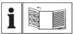
Overview
A Machine: 1 Left handle
2 Rotary knob for milling depth adjustment
3 Hand wheel for rotation speed preselection
4 Power cable
5 Switch block
6 On/Off switch
7 Right handle
8 Cap nut
9 Retaining screw
10 Baseplate
11 Sliding plate
12 Drill holes for suction adapter
13 Collet chuck 8 mm, preassembled (not visible)
14 Step limit
15 Guide rail
16 Spindle locking button
17 Depth stop
18 Locking screw of depth stop
19 Tightening lever
Accessories:
20 Suction adapter
21 2 recessed head screws
22 Collet chuck 6 mm
23 Centring tip with butterfly nut
24 Parallel stop
25 Template guide
26 Ball race
27 Combination wrench with long hole
28 Allen key
29 2 guide bars
30 Reducer piece (dust suction)
6-part cutter set:
31 Profile cutter ( 25mm R4 mm
32 Rounding cutter ( 22mm R6.3 mm)
33 V-notch cutter ( 12.7mm, 90^
34 Notch cutter ( 12mm
35 Notch cutter ( 6 mm)
36 Fillet cutter ( 22mm R6.3 mm)
Technical data
Rated input voltage 230 V~, 50 Hz
ldling speed n0 11000-30000 min-1
Power input 1200 W
Plunge depth 55 mm
Tool holder 6 mm/8 mm
Protection class
Protection category. IP20 *
Weight (incl. accessories) approx. 3.4 kg
Sound pressure level
(LpA) 90 dB(A); KpA = 3 dB
Sound power level
(LwA) 101 dB(A); KwA = 3 dB
Vibration (aH) 5.4 m/s²; K = 1.5 m/s²
- Plug for indoor use only.
Noise and vibration values have been determined according to the standards and regulations mentioned in the declaration of conformity.
Technical and optical changes may be undertaken in the course of further development without notice. All dimensions, references and information in this instruction manual are therefore not guaranteed. Legal claims made on the basis of the instruction manual can therefore not be considered as valid.
The stated vibration emission value was measured in accordance with a standard testing procedure and may be used to compare one power tool to another. The stated vibration emission value may also be used for a preliminary exposure assessment.

Warning: The vibration emission value may differ during actual use of the power tool from the stated value depending on the manner in which the power tool is used.
Safety precautions aimed at protecting the user should be based on estimated exposure under actual usage conditions (all parts of the operating cycle are to be considered, including, for example, times during which the power tool is turned off and times when the tool is turned on but is running idle).
Safety instructions
Ensure that the safety instructions are observed when operating the appliance.
Symbols on the appliance

Attention!

Pull out mains plug immediately, if the mains cable is damaged, entangled or severed.
Always remove the mains plug before working on the device.

Read the manual.

Wear ear protection.

Wear eye protection.

Wear breathing protection.

Electrical appliances must not be disposed of with the domestic waste.

Protection class II

Plug for indoor use only.
Symbols in the manual

Warning symbols with information on damage and injury prevention.

Instruction symbols (the instruction is explained at the place of the exclamation mark) with information on preventing damage.

Help symbols with information on improving tool handling.
General Safety Directions for Power Tools

WARNING! Read all safety directions and instructions.
Omissions in the compliance with safety directions and instructions can cause electrical shock, fire and/or severe injuries.
Retain all safety directions and instructions for future use.
The term "power tool" in the warnings refers to your mains-operated (corded) power tool or battery-operated (cordless) power tool.
Work area safety
- Keep work area clean and well lit. Cluttered or dark areas invite accidents.
-
Do not operate power tools in explosive atmospheres, such as in the presence of flammable liquids, gases or dust. Power tools create sparks which may ignite the dust or fumes.
-
Keep children and bystanders away while operating a power tool. Distractions can cause you to lose control.
Electrical safety
- Power tool plugs must match the outlet. Never modify the plug in any way. Do not use any adapter plugs with earthed (grounded) power tools. Unmodified plugs and matching outlets will reduce risk of electric shock
- Avoid body contact with earthed or grounded surfaces, such as pipes, radiators, ranges and refrigerators. There is an increased risk of electric shock if your body is earthed or grounded.
- Do not expose power tools to rain or wet conditions. Water entering a power tool will increase the risk of electric shock.
- Do not abuse the cord. Never use the cord for carrying, pulling or unplugging the power tool. Keep cord away from heat, oil, sharp edges or moving parts. Damaged or entangled cords increase the risk of electric shock.
- When operating a power tool outdoors, use an extension cord suitable for outdoor use. Use of a cord suitable for outdoor use reduces the risk of electric shock.
- If operating a power tool in a damp location is unavoidable, use a residual current device (RCD) protected supply. Use of an RCD reduces the risk of electric shock.
- If the supply cord of this power tool is damaged, it must be re
placed by a specially prepared cord available through the service organization.
Personal safety
- Stay alert, watch what you are doing and use common sense when operating a power tool. Do not use a power tool while you are tired or under the influence of drugs, alcohol or medication. A moment of inattention white operating power tools may result in serious personal injury.
- Use personal protective equipment. Always wear eye protection. Protective equipment such as dust mask, non-skid safety shoes, hard hat, or hearing protection used for appropriate conditions will reduce personal injuries.
- Prevent unintentional starting. Ensure the switch is in the off-position before connecting to power source and/or battery pack, picking up or carrying the tool. Carrying power tools with your finger on the switch or energising power tools that have the switch on invites accidents.
- Remove any adjusting key or wrench before turning the power tool on. A wrench or a key left attached to a rotating part of the power tool may result in personal injury.
- Do not overreach. Keep proper footing and balance at all times. This enables better control of the power tool in unexpected situations.
- Dress properly. Do not wear loose clothing or jewellery. Keep your hair, clothing and gloves away from moving
parts. Loose clothes, jewellery or long hair can be caught in moving parts.
- If devices are provided for the connection of dust extraction and collection facilities, ensure these are connected and properly used. Use of dust collection can reduce dust-related hazards.
Power tool use and care
- Do not force the power tool. Use the correct power tool for your application. The correct power tool will do the job better and safer at the rate for which it was designed.
- Do not use the power tool if the switch does not turn it on and off. Any power tool that cannot be controlled with the switch is dangerous and must be repaired.
- Disconnect the plug from the power source and/or the battery pack from the power tool before making any adjustments, changing accessories, or storing power tools. Such preventive safety measures reduce the risk of starting the power tool accidentally.
- Store idle power tools out of the reach of children and do not allow persons unfamiliar with the power tool or these instructions to operate the power tool. Power tools are dangerous in the hands of untrained users.
- Maintain power tools. Check for misalignment or binding of moving parts, breakage of parts and any other condition that may affect the power tool's operation. If damaged, have the power tool repaired before use. Many accidents are caused by
poorly maintained power tools.
- Keep cutting tools sharp and clean. Properly maintained cutting tools with sharp cutting edges are less likely to bind and are easier to control.
- Use the power tool, accessories and tool bits etc. in accordance with these instructions, taking into account the working conditions and the work to be performed. Use of the power tool for operations different from those intended could result in a hazardous situation.
- Carefully inspect the area to be cut and remove all wires or other foreign bodies.
Service
- Have your power tool serviced by a qualified repair person using only identical replacement parts. This will ensure that the safety of the power tool is maintained.
Safety notices for milling cutters

Warning! Milling can result in the formation of dusts hazardous to health (e.g. arising from materials with paints containing lead, materials containing asbestos or some wood types), which can pose a risk to the operator or persons nearby. Make sure that the workplace is well ventilated. Always wear safety goggles, safety gloves and respiratory protection. Attach a dust extraction system.
- Hold the power tool on the insulated handle surfaces, as the cutter might hit its own power
cable. Contact with a live wire can also cause a charge in metal parts of the appliance and result in an electric shock.
- Fasten and secure the workpiece by means of clamps or with another method on a stable underground. If you hold the workpiece only with your hand or against your own body, it will stay instable and this can lead to a loss of control.
- The permissible rotation speed of the attachment tools must be at least as high as the highest rotation speed indicated on the power tool. Accessories that run faster than the permissible speed can be destroyed.
- Cutters and other accessories must be exactly matching the tool holder (collet chuck) of your power tool. Attachment tools that are not exactly matching the tool holder of the power tool rotate unevenly, vibrate very strongly and can ultimately lead to a loss of control.
- Ensure that the cutter is assembled correctly. A cutter that is not assembled correctly can break during the milling or be ejected and present a risk of injury.
- Move the power tool against the workpiece only when it is turned on. Otherwise, there is a risk of kickback if the attachment tools jam in the workpiece.
- Do not put your hands in the cutting area and neither on the cutter. Hold the additional handle or the motor housing with your other hand. When holding the milling cutter with both hands, they cannot be injured by the cutter.
GB
- Never mill over metal objects, nails or screws. The milling cutter can be damaged and lead to increased vibrations.
- Use suitable detectors in order to find hidden supply lines or ask the local utility company. Contact with electrical cables can lead to electric shock and fire, contact with a gas pipe can result in an explosion. Damage to a water pipe can lead to property damaged and electric shock.
- Do not use any blunt or damaged tools. Blunt or damaged tools can cause uncontrollable situations.
- Hold the power tool tightly with both hands while working and ensure a secure footing. The power tool is guided more securely with both hands.
- Wait until the power tool has stopped before placing it down. The attachment tools can jam and lead to a loss of control over the power tool.
- Avoid contact with the tool or the workpiece immediately after processing. The parts may be hot and cause burn injuries.
Residual risks
Even if properly operating and handling this electric tool, some residual risks will remain. Due to its construction and build, this electric tool may present the following hazards:
a) Injuries caused by moving parts;
b) Ear damage if working without ear protection;
c) Lung damage, if suitable respiratory protection is not worn;
d) Eye injuries if no suitable eye protection is worn.
e) Damage to your health caused by swinging your hands and arms when operating the appliance for longer periods of time or if the unit is not held or maintained properly.

Warning! During operation, this electric tool generates an electromagnetic field which, under certain circumstances, may impair the functionality of active or passive medical implants. To reduce the risk of serious or lethal injuries, we recommend that persons with medical implants consult their doctor and the manufacturer of their medical implant before operating the machine.
Initial operation

Pull out the power plug before carrying out any work on the equipment. There is a risk of electrocution or of injury from moving parts.
Before you turn on the machine, you must
- insert the desired cutter,
- connect the dust suction,
- adjust the cutting depth,
- mount the parallel stop if necessary,
- clamp in the workpiece.
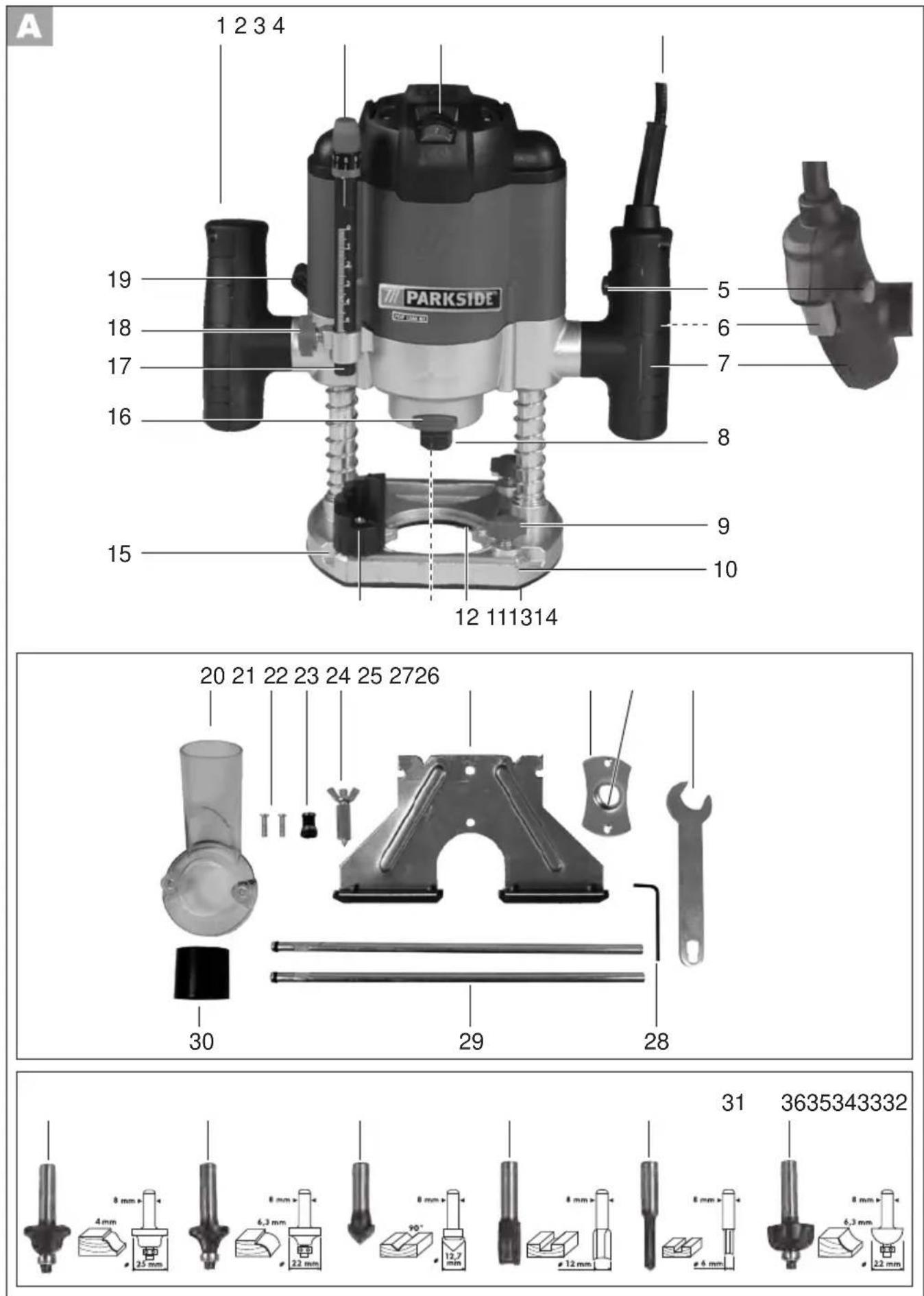
Inserting/changing cutters

To insert and replace cutters, wear protective gloves to prevent cuts and burns.

- Press the spindle locking button (16) on the front side of the machine and keep it pressed down.
- Use the combination wrench (27) to loosen the cap nut (8) as much
as needed, so that the cutter can be inserted.
- Release the spindle locking button (16).
- Insert the desired cutter into the already mounted collet chuck (13). The cutter shaft must be pushed in at least 20mm
- Use the combination wrench (27) to tighten the cap nut (8) while keeping the spindle locking button (16) pressed.

Tighten the cap nut only when a cutter is inserted. The collet chuck might get damaged.
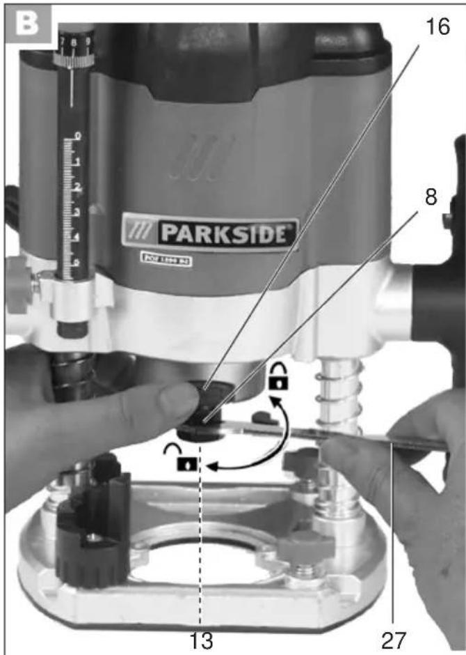
Change collet chuck
All cutters of the 6-part cutter set included in the delivery are provided with an 8-mm cutter shaft.
Change the collet chuck for cutters with a 6-mm cutter shaft.

- Press the spindle locking button (16) on the front side of the machine and keep it pressed down.
- Screw off the cap nut (8) using the combination wrench (27).
- Release the spindle locking button (16).
- Take out the 8-mm collet chuck (13) and insert the 6-mm collet chuck (22) that is included in the delivery.
- Screw the cap nut (8) loosely back on.
- Insert a cutter as described above B

Tighten the cap nut only when a cutter is inserted. The collet chuck might get damaged.
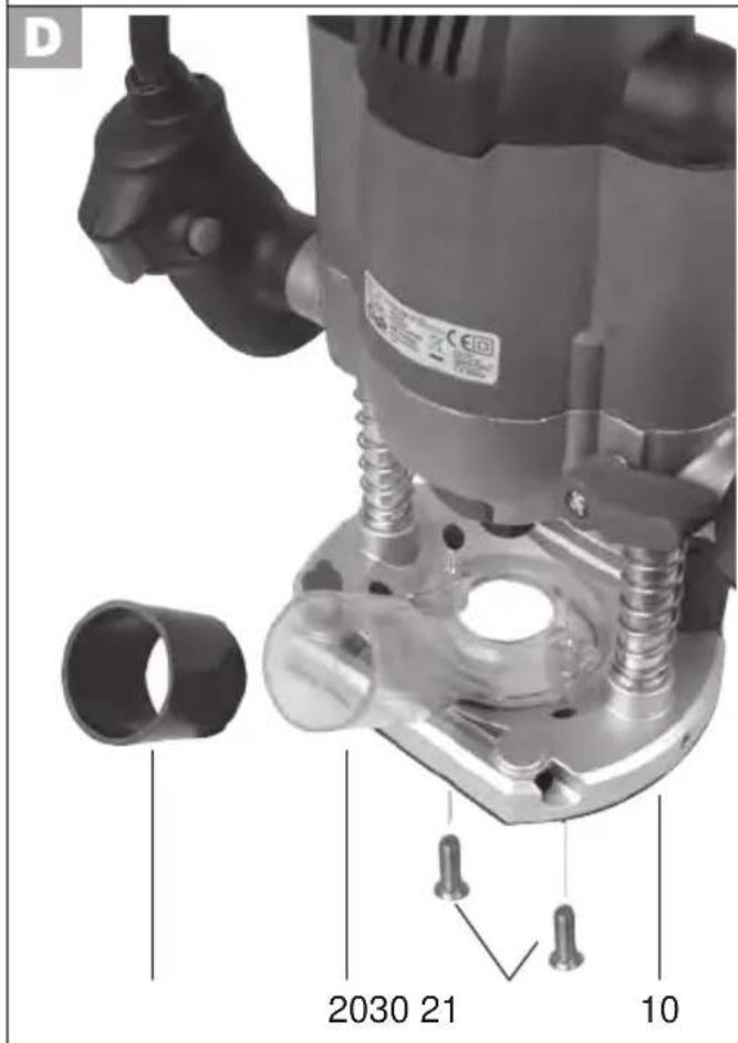
Connecting the suction adapter
You can reduce dust formation while you work by connecting a dust suction system.

- Fit the suction adapter (20) on the provided drill holes (12) in the baseplate (10).
- Screw on the 2 recessed head screws (21) from the bottom side of the baseplate (10).
- Fit the reducer part (30) on the suction adapter if needed.
- Connect the suction hose of a vacuum cleaner to the suction adaptor (20).

The vacuum cleaner must be suitable for the workpiece to be processed.
Use a special vacuum cleaner if dusts with hazard for health are created.
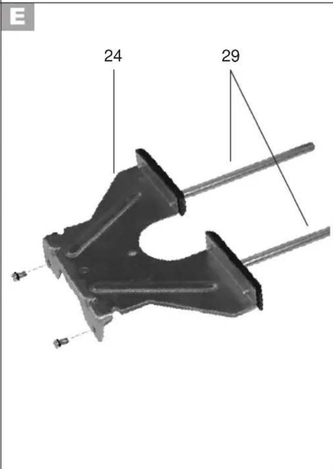
Mounting the parallel stop

- Screw both screws out of the guide bars (29).
- Screw the guide bars (29) onto the parallel stop (24).
Adjust cutting depth

The switch has 6 levels: 0 - 5 - 10 - 15 - 20 - 25 mm

- Place the machine with inserted cutter on the workpiece to be processed.
-
Turn the step limit (14) until it engages in the lowest step below the depth stop (17).
-
Release the locking screw (18) on the depth limit (17).
- Loosen the clamping lever (19) by pushing it upward.
- Slowly press down the machine until the cutter contacts the workpiece.
- Fasten the clamping lever (19) by pushing it to the left.
Rough adjustment:
- Slide the depth stop (17) downward until it rests on the step limit (14).
- Adjust the depth stop (17) to the desired cutting depth and tighten the locking screw (18).
Fine adjustment:
- For the fine adjustment, turn the rotary knob (2) to the desired measure, wherein one complete rotation equals 1mm : counter-clockwise rotation: greater cutting depth clockwise rotation: lesser cutting depth
- After the fine adjustment, you can set the scale below the rotary knob (2) to the "0" position. For this purpose, press the ring (2a) below the rotary knob downward and turn it into the desired position.

We recommend testing the cutting depth adjustment by means of a test cut on a reject piece.
Gradual milling
To mill in multiple steps with greater cutting depth, the cutting depth can be adjusted with the step limit (A 14).
- Turn the step limit (14) so that it engages in the highest step below the depth stop (A 17).
- Set the further cutting depth with the lower steps of the step limit (14).
Operation

Wear breathing protection (fine dust mask of protection class PPP2).
Switching on and off

- Connect the machine to the power supply.
Make sure that the net voltage matches the voltage rating indicated on the device's type plate.
- Switching on: Keep the safety lock (5) pressed and press the on/off switch (6). Then release the safety lock.
- Switching off: Release the on/off switch (6).
Pre-selecting the rotation speed
You can pre-select the maximum rotation speed on the handwheel for the rotation speed pre-selection (A 3). The on/off switch (A 6) can only be pressed up to the specified speed.
- Adjust the desired rotation speed on the handwheel for the rotation speed preselection (A 3).
1-2 = low rotation speed
3-4 = medium rotation speed
5-7 = high rotation speed
The suitable rotation speed is pre-selected depending on the work material, the cutter
type and the work conditions. With large cutter diameters and hard workpieces, choose lower rotation speeds and with small cutter dimensions and soft workpieces choose higher rotation speeds. The best way to find the suitable rotation speed is a test milling.

Never adjust the rotation speed during milling. Risk of injury!
Practical tips
Milling
Always mill in counter direction: in the process, the machine is moved counter to the rotation direction of the cutter.
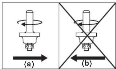

Never mill in the rotation direction (synchronous operation). There is the risk of accidents, as the machine might be torn out of your hands.
- Use only the cutter that has a specified permissible rotation speed, which is at least as high as the maximum rotation speed of the machine that is specified on the machine.
- Always use the proper tools.
-
Do not use any blunt or damaged tools or accessories.
-
Lead the power cable always towards the back and away from the machine during the milling.
- Fasten the workpiece securely on the work surface.
- Insert the cutter.
- Set the desired cutting depth and rotation speed.
- Turn the machine on.
- Loosen the clamping lever (19) and slowly press the machine downwards until it sits on the depth stop (A 17). Fasten the machine again using the clamping lever.
- Hold the machine tightly with both hands while working and mill with an even feed.
- After work, loosen the clamping lever (19) and move the machine upward.
- Turn off the device.
Edge and profile cutting
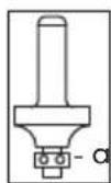
When edge or profile cutting without parallel stop, the cutter must be equipped with a stop ring (a) as guide.
- Move the turned on machine to the workpiece until it sits on the stop ring on the workpiece edge to be processed.
- Move the machine with both hands along the workpiece edge. Avoid excessive pressure.
Milling with parallel stop
You can mill notches and profiles with the parallel stop by moving the parallel stop along the workpiece edge at a pre-set distance.
-
Insert the parallel stop (24) with the guide bars (29) into the guide rails (15) of the baseplate (10). Tighten the retaining screws (9).
-
Move the turned on machine along the workpiece edge with lateral pressure on the parallel stop (24).
Milling with template guide
By means of the template guide (25), you can transfer contours from templates to workpieces.

Inserting the template guide:
- Screw off the suction adapter as applies.
- Insert the template guide (25) into the sliding plate (11). The ball race (26) must point down.
- Fasten the template guide (25) to the recessed head screws (21) that are included in the delivery.
Inserting the cutter:
- Insert a cutter that has a diameter smaller than the inner diameter of the template guide (25).
- Set the desired cutting depth (see "Initial operation").
Milling with template guide
- Loosen the clamping lever (19) and lower the machine downward until the previously set cutting depth is reached.
- Move the machine with protruding template guide (25) along the template. Apply slight pressure during this work.
The template must be at least as high as the ball race (26) of the template guide (25).
Milling with centring tip
By means of the centring tip, you can do circular milling work.
-
Turn the parallel stop (24) around so that the stop edge points up.
-
Screw on the centring tip (23) on the parallel stop by means of the butterfly nut. In the process, counter lock the centring tip in the long hole of the combination wrench (27).
- Screw the guide bars (29) of the parallel stop (24) on the baseplate (10) and tighten the retaining screws (9).
- Push the centring tip (23) in the marked centre of the circle to be cut.
- Move the machine circularly once in the circle around the centring tip (23).
Cleaning/maintenance

Ask our service centre to carry out any work that is not described in these instructions. Use only original parts. In this way you avoid damage to the appliance and possible injury to people.

Pull out the power plug before carrying out any work on the equipment. There is a risk of electrocution or of injury from moving parts.

Always wear protective gloves when handling cutters to avoid cutting yourself.
The following cleaning and servicing should be done regularly. This will ensure a long and reliable service life.
Cleaning

Do not spray the appliance with water and do not immerse it in water. Electric shock hazard!

Do not use cleaning agents or solvents. You may otherwise irreparably damage the appliance.
- Keep clean the ventilation slots, motor housing and handles of the appliance. Use a damp cloth or a brush.
General maintenance
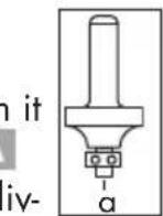
- Prior to every use, check the appliance for obvious defects such as loose, worn or damaged parts.
If the ball bearing (a) of a cutter has come loose, tighten it again using the Allen key (28) that is included in the delivery.
Storage
- Clean the device prior to storage.
- Store the appliance in a dry place well out of reach of children.
- Store the cutter in the packaging included in the delivery. Avoid contact with other metal parts or cutter blades.
Waste Disposal/environmental protection
Be environmentally friendly. Return the tool, accessories and packaging to a recycling centre when you have finished with them.
Electrical machines do not belong in domestic waste.
Take the equipment to a waste disposal site. The plastic and metal parts that are used can be separated out into pure grade, which allows recycling. Ask our Service Centre for details.
Defective units returned to us will be disposed of for free.
Spare parts/accessories
Spare parts and accessories can be obtained at www.grizzly-service.eu
If you do not have internet access, please contact the Service Centre via telephone (see "Service-Center" Page 73). Please have the order number mentioned below ready.
| Position instruction manual | Position exploded drawing | Description Order No. | |
| A 13/22 | 45/47/73 Set 1: Collet chuck set (6mm / 8mm) 91104251 | ||
| A 17 | 22 | Depth stop 91104250 | |
| A 20/30 | 49/51 Set 3: | Suction adapter + Reducer piece | 91104252 |
| A 24/29 | 65-70 Set 2: Parallel | stop + guide bars | 91104258 |
| A 25 | 63 | Template guide 91104253 | |
| A 27 | 71 | Combination wrench 91104256 | |
| A 31-36 | Set 4: | 6-part cutter set (MAN / n=max. 35000 / HW)* | 91104255 |
| 31 | Profil cutter ( | 25.0x12.0x8 / R 4 mm)** | |
| 32 | Rounding cutter ( | 22.0x11x8 / R 6.3 mm)** | |
| 33 | V-notch cutter (12.7x9.0x8 / ≤ 90°)** | ||
| 34 | Notch cutter ( | 12.0x20.0x8)** | |
| 35 | Notch cutter ( | 6.0x20.0x8)** | |
| 36 | Fillet cutter (22.0x13.x8 / R 6.3 mm)** |
- MAN = approved for manual feeds.
n = . rotation speed ()^-1 for which the cutter is approved.
HW = cutting blades are made of hard metal.
** Dimensions of the cutter (mm): Cutter diameter x length of the cutter head x shaft diameter R = radius of the profile (mm)

= angle of the V -notch
Troubleshooting
| Problem Possible cause | Use Error correction | |
| Appliance does not start | No mains voltageMain circuit breaker is tripped | Check the socket, power cable, line, power plug, repairs to be carried out by qualified electrician if necessary, check main circuit breaker. |
| On/off switch (A 6) is broken | Repair by Customer Care | |
| Motor faulty | ||
| Engine is slower and stops | Device is overloaded through workpiece | Reduce the pressure |
| Increase rotation speed | ||
| Workpiece unsuitable | ||
| The milling is not straight | The guide bars (A 29) of the parallel stop (A 24) are not mounted firmly. | If necessary, retighten the screws of the guide bars. |
| The milled work-piece has burn marks | Rotation speed too low Increase | rotation speed |
| Unsuitable or blunt cutter Change | the cutter | |
| Cutting depth is set too large | Use the step stop to mill in multiple steps | |
| The fringes of the milled part tear off, there are grooves and uneven parts in the milling | Cutter is worn out and dull Change | the cutter |
| Cutter blades are damaged Change | the cutter | |
| Dust is not being sucked off | Vacuum is not switched on Turn | on vacuum before milling |
| Suction hose or suction adaptor (A 20) is clogged | Remove clogging |
Guarantee
Dear Customer,
This equipment is provided with a 3-year guarantee from the date of purchase. In case of defects, you have statutory rights against the seller of the product. These statutory rights are not restricted by our guarantee presented below.
Terms of Guarantee
The term of the guarantee begins on the date of purchase. Please retain the original receipt. This document is required as proof of purchase.
If a material or manufacturing defect occurs within three years of the date of purchase of this product, we will repair or replace - at our choice - the product for you free of charge. This guarantee requires the defective equipment and proof of purchase to be presented within the three-year period with a brief written description of what constitutes the defect and when it occurred.
If the defect is covered by our guarantee, you will receive either the repaired product or a new product. No new guarantee period begins on repair or replacement of the product.
Guarantee Period and Statutory Claims for Defects
The guarantee period is not extended by the guarantee service. This also applies for replaced or repaired parts. Any damages and defects already present at the time of purchase must be reported immediately after unpacking. Repairs arising after expiry of the guarantee period are chargeable.
Guarantee Cover
The equipment has been carefully produced in accordance with strict quality guidelines and conscientiously checked prior to delivery.
The guarantee applies for all material and manufacturing defects. This guarantee does not extend to cover product parts that are subject to normal wear and may therefore be considered as wearing parts (e.g. cutter, accessories and carbon brushes) or to cover damage to breakable parts (e.g. switches, or parts made of glass).
This guarantee shall be invalid if the product has been damaged, used incorrectly or not maintained. Precise adherence to all of the instructions specified in the operating manual is required for proper use of the product. Intended uses and actions against which the operating manual advises or warns must be categorically avoided.
The product is designed only for private and not commercial use. The guarantee will be invalidated in case of misuse or improper handling, use of force, or interventions not undertaken by our authorised service branch.
Processing in Case of Guarantee
To ensure efficient handling of your query, please follow the directions below:
- Please have the receipt and identification number (IAN 275390) ready as proof of purchase for all enquiries.
- Please find the item number on the rating plate.
-
Should functional errors or other defects occur, please initially contact the service department specified below by telephone or by e-mail. You will then receive further information on the processing of your complaint.
-
After consultation with our customer service, a product recorded as defective can be sent postage paid to the service address communicated to you, with the proof of purchase (receipt) and specification of what constitutes the defect and when it occurred. In order to avoid acceptance problems and additional costs, please be sure to use only the address communicated to you. Ensure that the consignment is not sent carriage forward or by bulky goods, express or other special freight. Please send the equipment inc. all accessories supplied at the time of purchase and ensure adequate, safe transport packaging.
Repair service
For a charge, repairs not covered by the guarantee can be carried out by our service branch, which will be happy to issue a cost estimate for you.
We can handle only equipment that has been sent with adequate packaging and postage.
Attention: Please send your equipment to our service branch in clean condition and with an indication of the defect.
Equipment sent carriage forward or by bulky goods, express or other special freight will not be accepted.
We will dispose of your defective devices free of charge when you send them to us.
Service-Center
GB Service Great Britain
Tel.: 0871 5000 720
(£0.10/Min.)
E-Mail: grizzly@lidl.co.uk
IAN 275390
Importer
Please note that the following address is not a service address. Please initially contact the service centre specified above.
| Translation of the original EC declaration of conformity | |
| We hereby confirm that the Router POF 1200 B2 series Serial no. 20160800001 - 20160855404 conforms with the following applicable relevant version of the EU guidelines: | |
| 2006/42/EC • 2014/30/EU • 2011/65/EU* | |
| In order to guarantee consistency, the following harmonised standards as well as natio- nal standards and stipulations have been applied: | |
| EN 60745-1:2009/A11:2010 • EN 60745-2-17:2010 EN 55014-1:2006/A2:2011 • EN 55014-2:1997/A2:2008 EN 61000-3-2:2014 • EN 61000-3-3:2013 | |
| This declaration of conformity is issued under the sole responsibility of the manufacturer: | |
| Grizzly Tools GmbH & Co. KG Stockstädter Straße 20 D-63762 Großbostheim, Germany 20.08.2016 | Volker Lappas (Documentation Representative) |
- The object of the declaration described above satisfies the provisions of Directive 2011/65/EU of the European Parliament and the Council of 8 June 2011 on limiting the use of certain harmful substances in electrical and electronic appliances.