
Magnus 56 - Binoculars LEICA - Free user manual and instructions
Find the device manual for free Magnus 56 LEICA in PDF.
| Product type | Binoculars (viewing scope) |
| Brand | Leica |
| Model | Magnus 56 |
| Magnification | 2.4 - 16x |
| Objective diameter | 56 mm |
| Exit pupil | 12.4 - 3.5 mm |
| Field of view at 100 m | 2.6 - 17 m |
| Parallax correction | 50 m - ∞, adjustable |
| Eye relief | 90 mm |
| Diopter compensation | -4 / +3 dpt |
| Impact point adjustment range | 150 x 140 cm at 100 m |
| Click adjustment | approx. 10 mm (1/3 MOA) at 100 m |
| Central tube diameter | 30 mm, Zeiss rails |
| Thread for objective filter | M58 x 0.75 mm |
| Reticle illumination | Luminous dot, Day/Night modes, 60 increments, auto power off |
| Power supply | 1 lithium button cell 3V CR 2032 |
| Waterproofness | Up to 4 m, nitrogen filled |
| Housing material | Aluminum |
| Length | 360 mm |
| Weight | 785 g |
| Delivery contents | Scope, CR2032 battery, eyepiece/objective caps, instruction manual, warranty card, cloth, rail covers (depending on model) |
Frequently Asked Questions - Magnus 56 LEICA
User questions about Magnus 56 LEICA
0 question about this device. Answer the ones you know or ask your own.
Ask a new question about this device
Download the instructions for your Binoculars in PDF format for free! Find your manual Magnus 56 - LEICA and take your electronic device back in hand. On this page are published all the documents necessary for the use of your device. Magnus 56 by LEICA.
USER MANUAL Magnus 56 LEICA
VORWORT
natural_image
Line drawing of a hand inserting a small component into a pipe fitting (no text or symbols)natural_image
Simple target symbol with concentric circles and a central crosshair (no text or labels)
natural_image
Diagram of two mechanical components with red arrows indicating motion or rotation (no text or symbols)natural_image
Simple geometric diagram with concentric circles and a central crosshair (no text or symbols)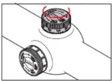
natural_image
Diagram of two mechanical components with red arrows indicating rotation or movement (no text or symbols)natural_image
Simple geometric diagram with concentric circles and a central dot, no text or symbols present.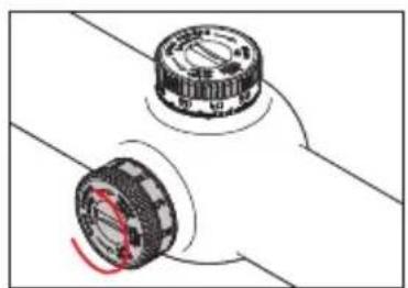
natural_image
Diagram of two mechanical components with a red circular highlight on their centers (no text or symbols)natural_image
Simple concentric circle diagram with a single black dot at the center (no text or symbols)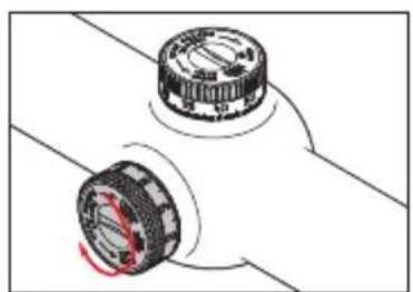
natural_image
Diagram of two mechanical components with rotating parts and a highlighted section (no text or symbols)natural_image
Hand using a tool to adjust or install a mechanical component (no text or symbols visible)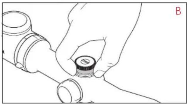
natural_image
Line drawing of a hand holding a small cylindrical component, no text or symbols presentThroughout the world, the name Leica stands for premium quality, accurate precision mechanics, optimum reliability and long service life.
We wish you a lot of enjoyment and every success with your new Leica Magnus telescopic sight.
Your Leica Magnus telescopic sight is equipped with an outstanding optical system, which delivers a clear, bright and brilliant image even under the toughest conditions, ensuring a reliable reticule at all times. It is also easy to operate and functional.
To enable you to make the best possible use of this high performance telescopic sight's features, we recommend that you read these instructions before use.
Attention:
As with binoculars, avoid looking directly at bright sources of light when using your Leica Magnus telescopic sight, to prevent eye injury.
CONTENTS
Foreword 19
Designation of parts 20
Package contents 20
Disposal of electrical and electronic equipment ..... 21
Inserting and changing the batteries 22
Battery capacity display 23
Mounting 24
Diopter compensation 24
Changing the magnification 25
Parallax compensation 25
Elevation and lateral adjustment 26
"Zeroing" the tower scales 28
Using the illuminated reticle 29
Automatic shutdown 30
Maintenance / cleaning 30
Spare parts 32
Technical data 33
Leica on the Internet 34
Leica information service 34
Leica customer care 35
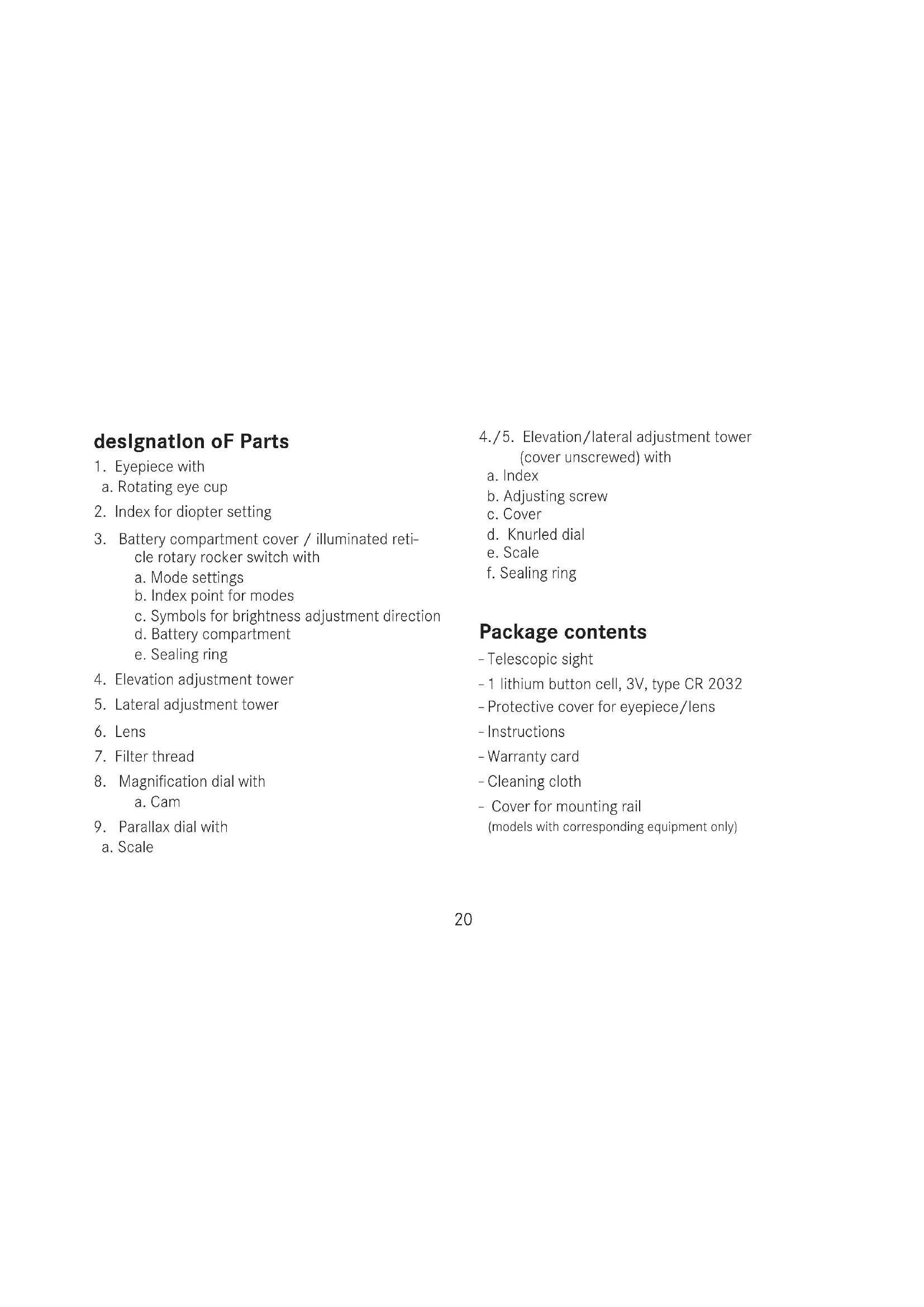
designation of Parts
- Eyepiece with
a. Rotating eye cup
-
Index for diopter setting
-
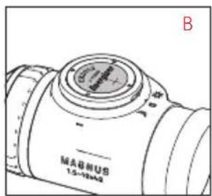
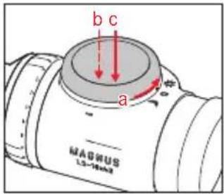
Battery compartment cover / illuminated reticle rotary rocker switch with
a. Mode settings
b. Index point for modes
c. Symbols for brightness adjustment direction
d. Battery compartment
e. Sealing ring
-
Elevation adjustment tower
-
Lateral adjustment tower
-
Lens
-
Filter thread
-
Magnification dial with
a. Cam
- Parallax dial with
a. Scale
4./5. Elevation/lateral adjustment tower (cover unscrewed) with
a. Index
b. Adjusting screw
c. Cover
d. Knurled dial
e. Scale
f. Sealing ring
Package contents
- Telescopic sight
- 1 lithium button cell, 3V, type CR 2032
- Protective cover for eyepiece/lens
- Instructions
- Warranty card
- Cleaning cloth
- Cover for mounting rail
(models with corresponding equipment only)
dIsPosal of electrical and electronic equIPment
(Applies within the EC, and for other European countries with segregated waste collection systems)
This device contains electrical and/or electronic components and should therefore not be disposed of in general household waste!
Instead it should be disposed of at a recycling collection point provided by the local authority. This costs you nothing.
If the device itself contains removable batteries or rechargeable batteries, these should first be removed and, if necessary, properly disposed of (refer to the specifications in the manual for your device).
Further information on this point is available at your local administration, your local waste collection company, or in the store where you purchased this device.
INSERTING AND CHANGING THE BATTERY
Leica telescopic sights with illuminated reticle are fitted with a 3 Volt lithium button cell, type CR 2032 to save energy.
Note:
The life of a battery depends not just on the usage profile but on many other factors and can therefore differ widely.
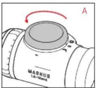
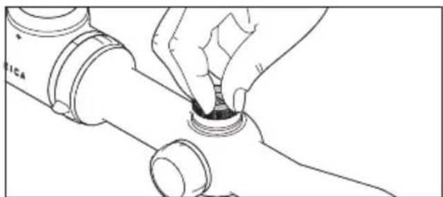
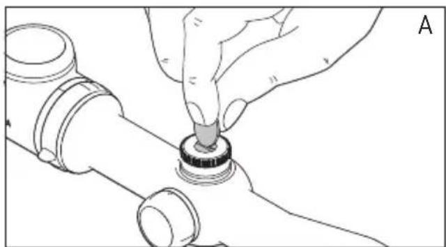
- Open the cover (3) on the battery compartment (3d) by turning it anticlockwise (A).
- Insert the battery with the positive contact pointing upwards (B).
- Close the cover again. To do this, turn it clockwise until you feel resistance from the rubber sealing ring (3e).
Important:
Do not exert force when closing the cover.
BATTERY CAPACITY DISPLAY
The illuminated dot from the reticle is used for the display. The display appears for the first 10 s after turning on:
Capacity Display
| Sufficient | Illuminated dot lit continuously |
| Low | Illuminated dot goes out |
| regularly for a short time |
Weak Illuminated point flashes evenly
Note:
• After the illuminated reticle is automatically turned off and back on (see p. 30), the display is not repeated.
- With the factory default settings, i.e. when the telescopic sight is delivered, this display is turned on. However, you can turn it off (see below).
Turning the capacity display on and off
- Set the rotary rocker switch (3) to day mode ("sun" setting) (a).
- Use the rotary rocker switch to set the minimum brightness (see p. 29) and then release it (b).
- Hold down the left of the rotary rocker switch for at least 20s (c).
- The illuminated dot flashes to confirm your setting (for the first 10s after adjustment):
Status Display
| On | Illuminated dot briefly lights up regularly |
| Off | Illuminated dot briefly lights up twice regularly |
Note:
Your setting is retained both after manually turning the illuminated reticle off and on, and after changing the battery.
Mounting
The first requirement for perfect targeting is proper mounting of the telescopic sight on the weapon. There are a variety of different fittings available in specialist retailers for this purpose.
We recommend consulting a specialist workshop for advice on mounting, making sure that they achieve a flush and stress-free construction. The workshop should only use high quality components from well-known manufacturers for mounting, which offer the same quality as your Leica Magnus telescopic sight.
dloPter coMPensation
The diopter compensation allows you to adjust your Leica Magnus telescopic sight to your eye. To do this, turn the eye cup (1a) on the eyepiece (1) so that you can see the reticle with the maximum sharpness. To achieve the most accurate setting possible, we recommend
- pointing the telescopic sight at a neutral, light background, and
- first turning the eye cup all the way to the left, so that you can then turn it back from this position to the right until you find the best sharpness for the reticle. This method takes into account the accommodative capacity of the eye, thus ensuring an optimum setting.
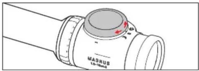
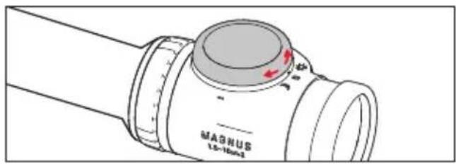
changing the Magnification
To change the magnification, turn the dial (8) - to the right to reduce the magnification and to the left to increase it. The cam (8a) improves orientation in darkness: If it is pointing upwards, approximately the middle magnification is set.
ParallaX coMPensation
Leica Magnus telescopic sights up to a maximum magnification of 12x are calibrated to a range of 100 m without parallax, which means that you can simultaneously see the reticle and a target with perfect sharpness at this range.
Any variations in the point of impact due to the eye being not precisely centered are usually negligible.
At higher magnifications, however, these variations need to be taken into account. Therefore, telescopic sights with magnification ranges above 12x feature parallax compensation.
To use this feature, on the corresponding dial (9) for the tower on the left of the barrel until you can see the target with absolute sharpness. To ensure that the setting is as accurate as possible, we recommend always using the strongest magnification. An optimum setting is achieved when the reticle and image do not move against each other when you change the position of the eye relative to the eyepiece.
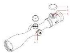
eleVatlon and lateral adjust-Ment
- Mount the telescopic sight on the weapon (see p. 24).
- Point the reticle and the weapon's running axis with the two adjusting towers at the selected zero-ing range (e.g. 100 m). This can be done using a laser cartridge, for example.
- Fire a test shot to establish the point of impact. It is beneficial to fix the weapon in position on a shooting rest or sandbags.
- Without changing the position of the weapon, adjust the reticle using the two adjusting towers (4/5) precisely to the target.
natural_image
Line drawing of a hand inserting a small component into a pipe fitting (no text or symbols)This is done using the two adjusting towers - (4) for the elevation, (5) for lateral, and in the same way in both cases:
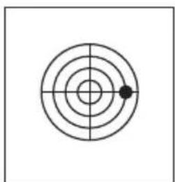
- First unscrew the cover (4c/5c) anticlockwise. When the cover is removed, the knurled dial (4d/5d) is visible, along with the associated scale ring (4e/5e) and the corresponding index point (4a/5a).
- Then make the settings with the knurled dial. The dial has very fine graduations, and a click corresponds to a variation in the point of impact of around 10 mm/ ^1/_3 MOA at 100 m (not taking account of ballistic conditions).
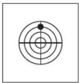
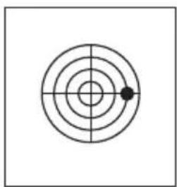
If the point of impact is high (high shot), turn the knurled dial (4d) anticlockwise,
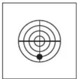
Make the lateral adjustments in the same way: If the point of impact is right (right shot), turn the knurled dial (5d) anticlockwise,
natural_image
Simple target symbol with concentric circles and a central crosshair (no text or labels)
natural_image
Diagram of two mechanical components with red arrows indicating motion or rotation (no text or symbols)or turn clockwise for a low point of impact (low shot).
natural_image
Simple geometric diagram with concentric circles and a single black dot at the center (no text or symbols)
natural_image
Diagram of two mechanical components with a red circular highlight on their centers (no text or symbols)or turn clockwise if the point of impact is left (left shot).
natural_image
Simple concentric circle diagram with a central crosshair and a small black dot at the center (no text or symbols)
natural_image
Diagram of two mechanical components with red arrows indicating motion or rotation (no text or symbols)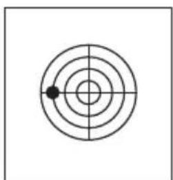
natural_image
Simple concentric circle diagram with a single black dot at the center (no text or symbols)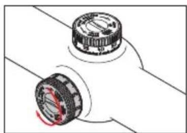
natural_image
Diagram of two mechanical components with rotating parts, no text or symbols present"zerolng" the tower scales
(same procedure for both towers)
The process is initially the same as that described in the previous section (points 1 and 2).
Then,
- While holding the knurled dial (4d/5d), unscrew the adjusting screw (4b/5b) with a coin (A), and
- Turn the scale dial (4e/5e) until the zero is lined up with the index point (4a/5a) (B).
- Finally, the setting is fixed by tightening the adjusting screw while holding the knurled dial (4d/5d)..
Once you have done this for both scale dials, you can reliably make the initial setting at the zeroing range after any kind of adjustment by returning to the 0 positions, without the need to remember or make a note of anything.
natural_image
Hand inserting a small component into a pipe fitting (no text or symbols visible)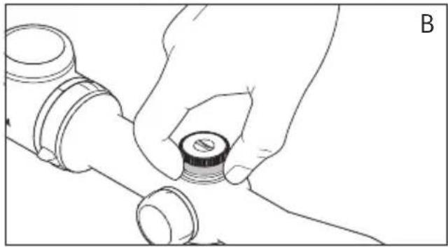
natural_image
Line drawing of a hand holding a small cylindrical component, no text or symbols presentUSING THE ILLUMINATED RETICLE
The illuminated element of Leica Magnus telescopic sights consists of a central illuminated dot for all reticle types.
Note:
Details of the different reticle types can be found at: http://de.leica-camera.com/sport_optics/rifle_scopes_magnus/Absehen/
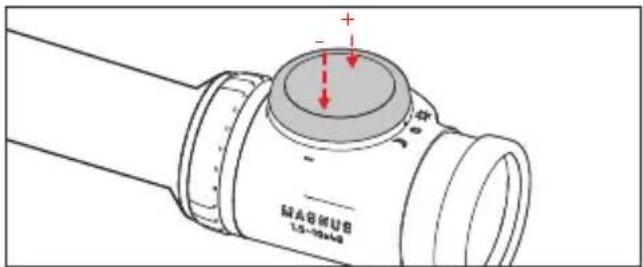
You can use the rotary rocker switch (3) to choose between three modes, indicated by corresponding markings:
Central switch position = Off "Moon" setting = Night mode "Sun" setting = Day mode

Day and night mode differ in terms of the brightness adjusting ranges for the illuminated dot. In both modes, you can adjust the brightness in 60 increments to the conditions or use or your own preferences.
This is also done using the rotary rocker switch: Pressing to the left reduces the brightness, pressing to the right increases it. Press once for a single increment or hold down to increment continuously.
Note:
Your settings are retained even after turning off and on again.
autoMatlc shutdown
Regardless of the selected mode, the illuminated reticle is deactivated automatically to conserve the battery in various situations, which correspond to not being used when hunting:
- If the telescopic sight is not moved for longer than 3 minutes (for example in a hide)
- If the telescopic sight is tilted to the side by more than 45^ (for example when the weapon is laid down temporarily)
- If the telescopic sight is tilted more than around 80^ upwards or around 65^ downwards or is vertical (for example when shouldering the weapon). As soon as these conditions no longer apply, the illuminated dot is reactivated with the brightness set previously.
Maintenance / cleaning
Your Leica Magnus telescopic sight does not require any special maintenance. Coarse dirt particles, such as sand, should be removed with a fine hair brush or blown away. Marks such as fingerprints on the front lens and eyepiece lenses can be cleaned with a damp cloth and then wiped off with a soft, clean leather or dust-free cloth. Do not exert heavy pressure when wiping highly soiled lens surfaces. Although the coating is highly abrasion resistant, it can be damaged by sand or salt crystals.
The housing should only be cleaned with a moist leather cloth. Using dry cloths brings a risk of static charge.
Alcohol and other chemical solutions must not be used to clean the optical system or the housing.
Important:
- Make sure you protect your telescopic sight from impacts.
- Store your telescopic sight in a well ventilated, dry and cool location, particularly to prevent the formation of fungus in humid climates.
- Leica telescopic sights are water tight to a depth of 4m (0.4 bar). This is the case if the seals are perfect, which is guaranteed if the covers on the elevation and lateral adjustment and the battery compartment cover (3/4c/5c) are screwed tightly against the respective seals (3e/4f/5f). Make sure that these seals are undamaged. If they are damaged, they should be replaced immediately.
- Do not attempt to dismantle the product. Repairs should be carried out exclusively by Leica Customer Care centers.
- In addition to the type designation, every Leica telescopic sight has its “personal” serial number. Note this number in your documentation for security.
sPare Parts
If you should require any spare parts for your Leica telescopic sight, e.g. screw-on cap, seals or covers, please contact our Customer Care department (see p. 35 for address) or the Leica office in your country (see warranty card for addresses).
TECHNICAL DATA
| Leica Magnus models 1 - 6.3 | ^1 × 24^2 1.5 | 10 | ^1 × 42^2 2.4 | 16 | ^1 × 56^2 |
| Exit pupil 12.4 - 3.8 mm 12.4 - 4.2 mm | 12.4 - 3.5 mm | ||||
| Field of vision at max./min. 6.5 /43.2 m Magnification (m/100 m) | 4.1 / 26 m 2.6 /17 m | ||||
| Parallax adjustment 100 m 100 m 50 m | -∞, adjustable | ||||
| Exit pupil longitudinal distance 90 mm | |||||
| Coating Aqua DuraTM | |||||
| Transmission factor | TD/TN ≥91 % | ||||
| Diopter compensation | - 4/+3 dpt. | ||||
| Reticle adjustment distance per click | Approx. 10mm ( ^1/_3 MOA) per click / 100 m | ||||
| Point of impact adjustment range | 200 x 140 cm | 150 x 140 cm | 150 x 140 cm | ||
| Center tube diameter | 30 mm, Zeiss internal rail | ||||
| Filter thread, lens side | - | M46 x 0.75 mm | M58 x 0.75 mm | ||
| Water tightness | To 4 m, nitrogen filled | ||||
| Housing material | Aluminum | ||||
| Reticle illumination | Illuminated dot, turned on and off, choice of day and night mode,brightness adjustable in 60 increments for each, automatic shutdown and activation | ||||
| Length | 272 mm | 317 mm | 360 mm | ||
| Weight | 570 g | 620 g | 785 g | ||
^1 Magnification
^2 Lens diameter
lelca on the Internet
Current information about products, newly introduced products, events and the Leica company is available on our homepage on the Internet at:
http://www.leica-camera.de
lelca InForMatlon serVIce
The Leica information service can provide you with an answer to any technical application questions relating to the Leica range either in writing, on the telephone or by e-mail.
Leica Camera AG
Information Service
PO Box 1180
D-35599 Solms
Leica AG's customer care centre, or the repair service of the Leica national offices, is available to assist you in maintaining your Leica equipment or in case of damage.
Leica Camera AG
Customer Care
coMPensation dloPtrlque
natural_image
Line drawing of a hand inserting a small component into a pipe fitting (no text or symbols)natural_image
Simple target symbol with concentric circles and a central crosshair (no text or labels)
natural_image
Diagram of two mechanical components with red arrows indicating motion or rotation (no text or symbols)natural_image
Simple geometric diagram with concentric circles and a central crosshair (no text or symbols)
natural_image
Diagram of two mechanical components with red arrows indicating rotation or movement (no text or symbols)natural_image
Simple geometric diagram with concentric circles and a single black dot at the center (no text or symbols)
natural_image
Diagram of two mechanical components with a red circular highlight on their centers (no text or symbols)natural_image
Simple concentric circle diagram with a single black dot at the center (no text or symbols)
natural_image
Diagram of two mechanical components with rotating parts, no text or symbols presentnatural_image
Hand inserting a small component into a pipe fitting (no text or symbols visible)
natural_image
Line drawing of a hand holding a small cylindrical component, no text or symbols presentUTILISATION DU RETICULE LUMINEUX
Position intermédiaire = Hors tension Position "Lune" = Mode Nuit Position "Soleil" = Mode Jour
natural_image
Line drawing of a hand inserting a small component into a pipe fitting (no text or symbols)natural_image
Simple target symbol with concentric circles and a central crosshair (no text or labels)
natural_image
Diagram of two mechanical components with red arrows indicating motion or rotation (no text or symbols)natural_image
Simple geometric diagram with concentric circles and a central crosshair (no text or symbols)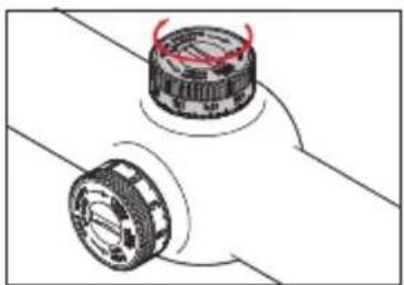
natural_image
Diagram of two mechanical components with red arrows indicating motion or rotation (no text or symbols)natural_image
Simple concentric circle diagram with a single black dot at the center (no text or symbols)
natural_image
Diagram of two mechanical components with a red circular highlight on their centers (no text or symbols)natural_image
Simple concentric circle diagram with a single black dot at the center (no text or symbols)
natural_image
Diagram of two mechanical components with rotating parts, no text or symbols presenttorenschaal "nullen"
natural_image
Hand using a tool to adjust or install a mechanical component (no text or symbols visible)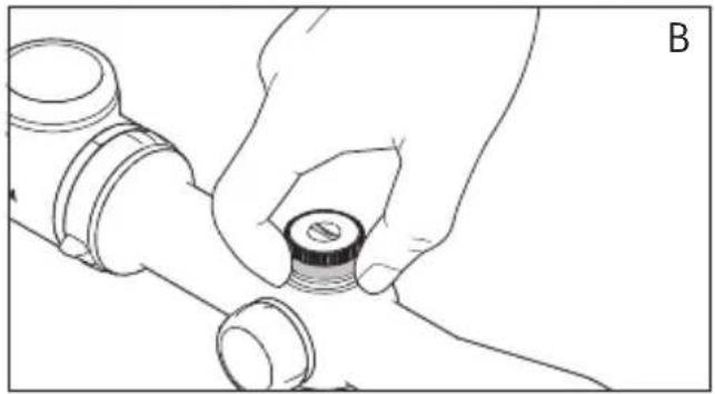
natural_image
Line drawing of a hand adjusting a pipe fitting with a circular component (no text or symbols)natural_image
Line drawing of a hand adjusting a small component on a pipe fitting (no text or symbols)natural_image
Simple target symbol with concentric circles and a central crosshair (no text or labels)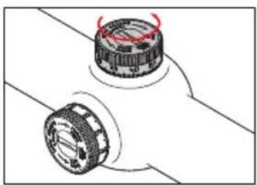
natural_image
Diagram of two mechanical components with red arrows indicating motion or rotation (no text or symbols)natural_image
Simple geometric diagram with concentric circles and a central crosshair (no text or symbols)
natural_image
Diagram of two mechanical components with red arrows indicating rotation or movement (no text or symbols)natural_image
Simple concentric circle diagram with a single black dot at the center (no text or symbols)
natural_image
Diagram of two mechanical components with a red circular highlight on their centers (no text or symbols)natural_image
Simple concentric circle diagram with a single black dot at the center (no text or symbols)
natural_image
Diagram of two mechanical components with rotating parts, no text or symbols presentnatural_image
Hand inserting a small component into a pipe fitting (no text or symbols visible)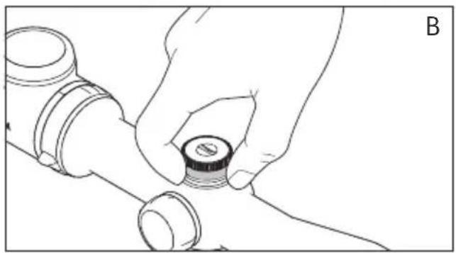
natural_image
Line drawing of a hand holding a small cylindrical component, no text or symbols presentIMPIEGO DEL RETICOLO DI ACCENSIONE
natural_image
Line drawing of a hand inserting a small component into a pipe fitting (no text or symbols)natural_image
Simple target symbol with concentric circles and a central crosshair (no text or labels)
natural_image
Diagram of two mechanical components with red arrows indicating motion or rotation (no text or symbols)natural_image
Simple geometric diagram with concentric circles and a central crosshair (no text or symbols)
natural_image
Diagram of two mechanical components with red arrows indicating motion or rotation, no text or symbols presentnatural_image
Simple geometric diagram with concentric circles and a central dot (no text or symbols)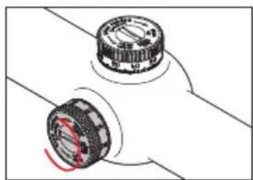
natural_image
Diagram of two mechanical components with a red circular highlight on their centers (no text or symbols)natural_image
Simple concentric circle diagram with a single black dot at the center (no text or symbols)
natural_image
Diagram of two mechanical components with rotating parts, no text or symbols presentnatural_image
Hand using a tool to adjust or install a mechanical component (no text or symbols visible)
natural_image
Line drawing of a hand holding a small cylindrical component, no text or symbols presentnatural_image
Line drawing of a hand inserting a small component into a pipe fitting (no text or symbols)natural_image
Simple target symbol with concentric circles and a central crosshair (no text or labels)
natural_image
Diagram of two mechanical components with red arrows indicating motion or rotation (no text or symbols)ved lavtliggende treffpunktposisjon, medurs.
natural_image
Simple concentric circle diagram with a single black dot at the center (no text or symbols)
natural_image
Diagram of two mechanical components with a red circular highlight on their centers (no text or symbols)dersom treffpunktet ligger til venstre, dreies det medurs.

natural_image
Simple geometric diagram with concentric circles and a central crosshair (no text or symbols)
natural_image
Diagram of two mechanical components with red arrows indicating rotation or movement (no text or symbols)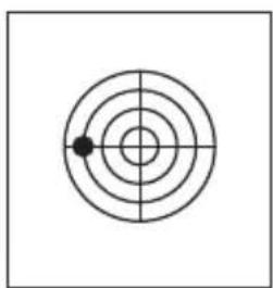
natural_image
Simple concentric circle diagram with a single black dot at the center (no text or symbols)
natural_image
Diagram of two mechanical components with rotating parts, no text or symbols present117117117
«nullIng» aV tÅrnskalaene
natural_image
Hand using a tool to adjust or install a mechanical component (no text or symbols visible)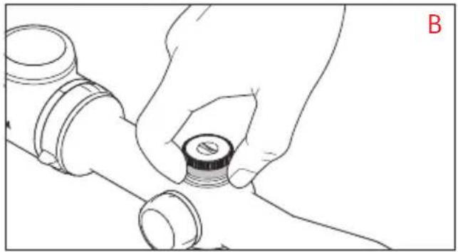
natural_image
Line drawing of a hand holding a small mechanical component (no text or symbols)BRUK AV LYSPUNKTTRÅDKORS
Trådkorset i Leica Magnus kikkertsikter har et lyspunkt i midten, dette gjelder for alle typer trådkors.
Merk:
Detaljer for de forskjellige typer trådkors finner du på: http://de.leica-camera.com/sport_optics/rifle_sco-pes_magnus/Absehen/
natural_image
Line drawing of a hand adjusting a small component on a pipe fitting (no text or symbols)natural_image
Simple concentric circle diagram with a black dot at the center (no text or symbols)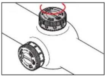
natural_image
Mechanical assembly diagram showing two rotating components with red motion arrows (no text or symbols)natural_image
Simple concentric circle diagram with a single black dot at the center (no text or symbols)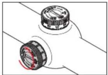
natural_image
Diagram of two mechanical components with a red circular mark indicating rotation (no text or symbols)natural_image
Simple concentric circle diagram with crosshair lines and a small black dot at the center (no text or symbols)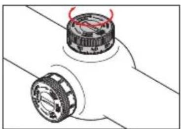
natural_image
Mechanical assembly diagram showing two rotating components with red motion arrows (no text or symbols)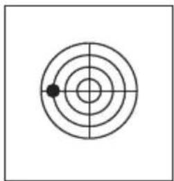
natural_image
Simple concentric circle diagram with a single black dot at the center (no text or symbols)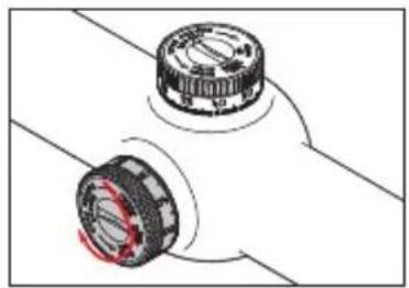
natural_image
Diagram of two mechanical components with no visible text or symbols135135135
タワー目盛りの「ゼロ設定」
(やり方は二つのタワーとも同じです)
natural_image
Hand using a tool to adjust or install a mechanical component (no text or symbols visible)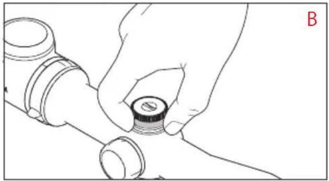
natural_image
Line drawing of a hand holding a small mechanical component (no text or symbols)発光鏡内目盛りの使用
natural_image
Line drawing of a hand adjusting a small component on a pipe fitting (no text or symbols)natural_image
Simple target symbol with concentric circles and a central dot (no text or labels)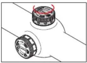
natural_image
Diagram of two mechanical components with red arrows indicating rotation or movement (no text or symbols)natural_image
Simple geometric diagram with concentric circles and a central dot, no text or symbols present.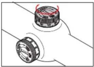
natural_image
Diagram of two mechanical components with red arrows indicating rotation or movement (no text or symbols)natural_image
Simple concentric circle diagram with a central dot and crosshairs (no text or symbols)
natural_image
Diagram of two mechanical components with a red circular highlight on their centers (no text or symbols)natural_image
Simple concentric circle diagram with a single black dot at the center (no text or symbols)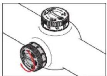
natural_image
Diagram of two mechanical components with rotating parts, no text or symbols presentnatural_image
Hand using a tool to adjust or install a mechanical component (no text or symbols visible)
natural_image
Line drawing of a hand holding a small cylindrical component, no text or symbols present
- VORWORT
- Attention:
- CONTENTS
- designation of Parts
- Package contents
- dIsPosal of electrical and electronic equIPment
- INSERTING AND CHANGING THE BATTERY
- Note:
- Important:
- BATTERY CAPACITY DISPLAY
- Turning the capacity display on and off
- Mounting
- dloPter coMPensation
- changing the Magnification
- ParallaX coMPensation
- eleVatlon and lateral adjust-Ment
- "zerolng" the tower scales
- USING THE ILLUMINATED RETICLE
- autoMatlc shutdown
- Maintenance / cleaning
- sPare Parts
- lelca on the Internet
- lelca InForMatlon serVIce
- coMPensation dloPtrlque
- UTILISATION DU RETICULE LUMINEUX
- torenschaal "nullen"
- IMPIEGO DEL RETICOLO DI ACCENSIONE
- «nullIng» aV tÅrnskalaene
- BRUK AV LYSPUNKTTRÅDKORS
- Merk:
- タワー目盛りの「ゼロ設定」
- 発光鏡内目盛りの使用
Brand : LEICA
Model : Magnus 56
Category : Binoculars