Park 200 - Parking sensor CALIBER - Free user manual and instructions
Find the device manual for free Park 200 CALIBER in PDF.
| Product type | Parking sensor |
| Brand | Caliber |
| Model | Park 200 |
| Rated voltage | DC 12V |
| Operating range | DC 9V - 18V |
| Rated current | 20 mA - 200 mA |
| Detection distance | 0,2 - 1,5 m |
| Display distance | 0,3 - 1,5 m |
| Ultrasonic frequency | 40 kHz |
| Operating temperature | -30°C to 80°C |
| Number of sensors | 4 pieces |
| Display type | Three-color LED digital (green, yellow, red) |
| Direction indicator | Left/right LED |
| Audible alarm | 3 levels (short beep, continuous beep, long tone) |
| ON/OFF switch | Yes |
| Power supply | Via reverse lights (12V) |
| Sensor type | Insertable |
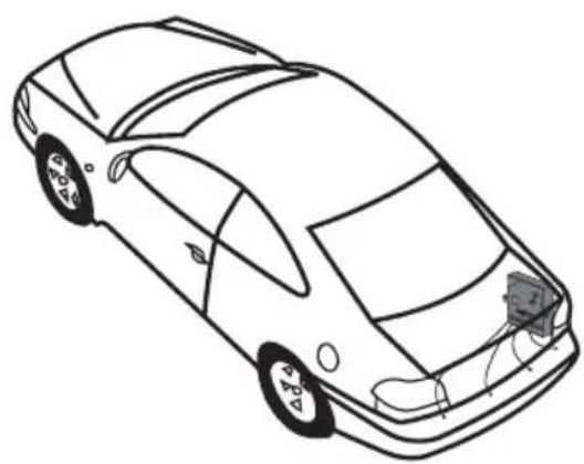
| Installation | Rear bumper |
| Safety | Immediate stop if object detected in danger zone |
| Maintenance and cleaning | Clean sensors from snow, ice, mud; avoid standing water |
| Spare parts and repairability | Specific sensors and control unit; replace the system if faulty |
Frequently Asked Questions - Park 200 CALIBER
User questions about Park 200 CALIBER
0 question about this device. Answer the ones you know or ask your own.
Ask a new question about this device
Download the instructions for your Parking sensor in PDF format for free! Find your manual Park 200 - CALIBER and take your electronic device back in hand. On this page are published all the documents necessary for the use of your device. Park 200 by CALIBER.
USER MANUAL Park 200 CALIBER
The Parking sensor is an appliance for the driver! Caliber Europe BV is not responsible for any damage to or with the vehicle as a result of using the system.
TO USER
Thank you for choosing and using the CALIBER Reverse Radar System. To insure the best performance and avoid any false alarm or function failure, please kindly read this manual carefully and install it accordingly.
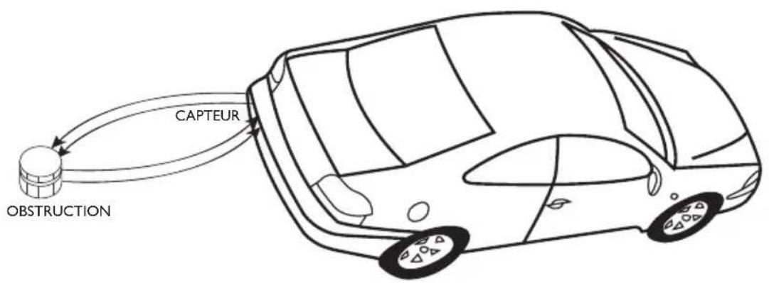
SYSTEM PRINCIPLE
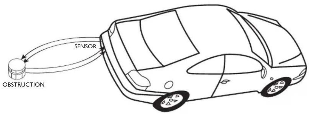
Caliber Reverse Radar System uses the technology of ultrasonic wave. When the ultrasonic waves meet the objects, it will be returned and transformed to electric signals. Then the CPU calculates the distance between the car and the object with the enlarged signals and alarm unit will warn the driver of the distance with audio and visual signals.
TECHNICAL SPECIFICATIONS
- Rated voltage: DC12V Operating range: DC9V-18V Rated current: 20mA-200mA
- Detecting distance: 0,2 - 1,5m Display distance: 0,3 - 1,5m
- Ultrasonic frequency: 40 KhZ Working temperature: -30 80^ C Sensor quantity: 4 pcs
FUNCTIONS
- Numeric LED
- Direction indicator in three color LED
- Three step sounds
ON/OFF switch
"BIBI" alarm sound

USER MANUAL

ALARM MODE
- AWARENESS: Safe mode
DISTANCE: 100-150 cm
SOUND: Bi. Bi. Bi
DISTANCE SHOW: 1.0 - 1.5m
LED INDICATOR: Green, left & right indicator
- AWARENESS: Alert mode
DISTANCE: 50-90 cm
SOUND: BiBiBi (step-up)
DISTANCE SHOW: 0.5 - 0.9m
LED INDICATOR: Yellow, left & right indicator
- AWARENESS: Close mode
DISTANCE: 0-40 cm
SOUND:Biii
DISTANCE SHOW: 0.0m
LED INDICATOR: Red, left & right indicator
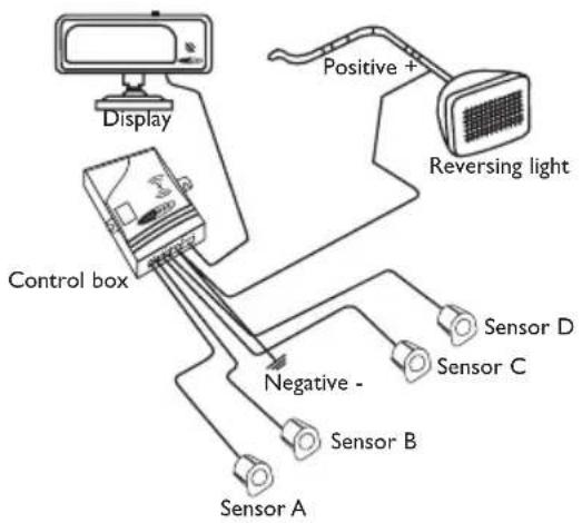
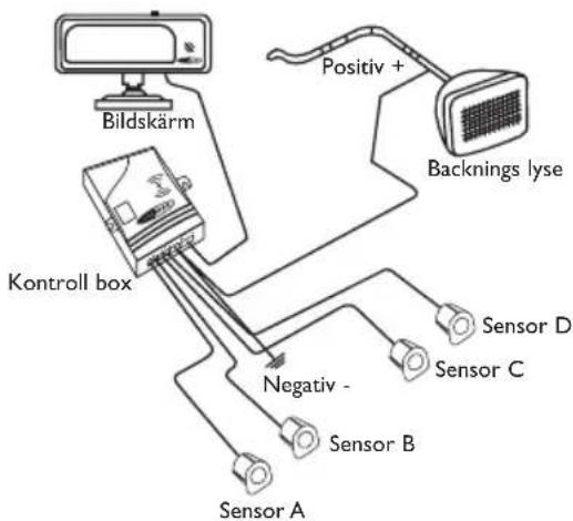
INSTALLATION DIAGRAM

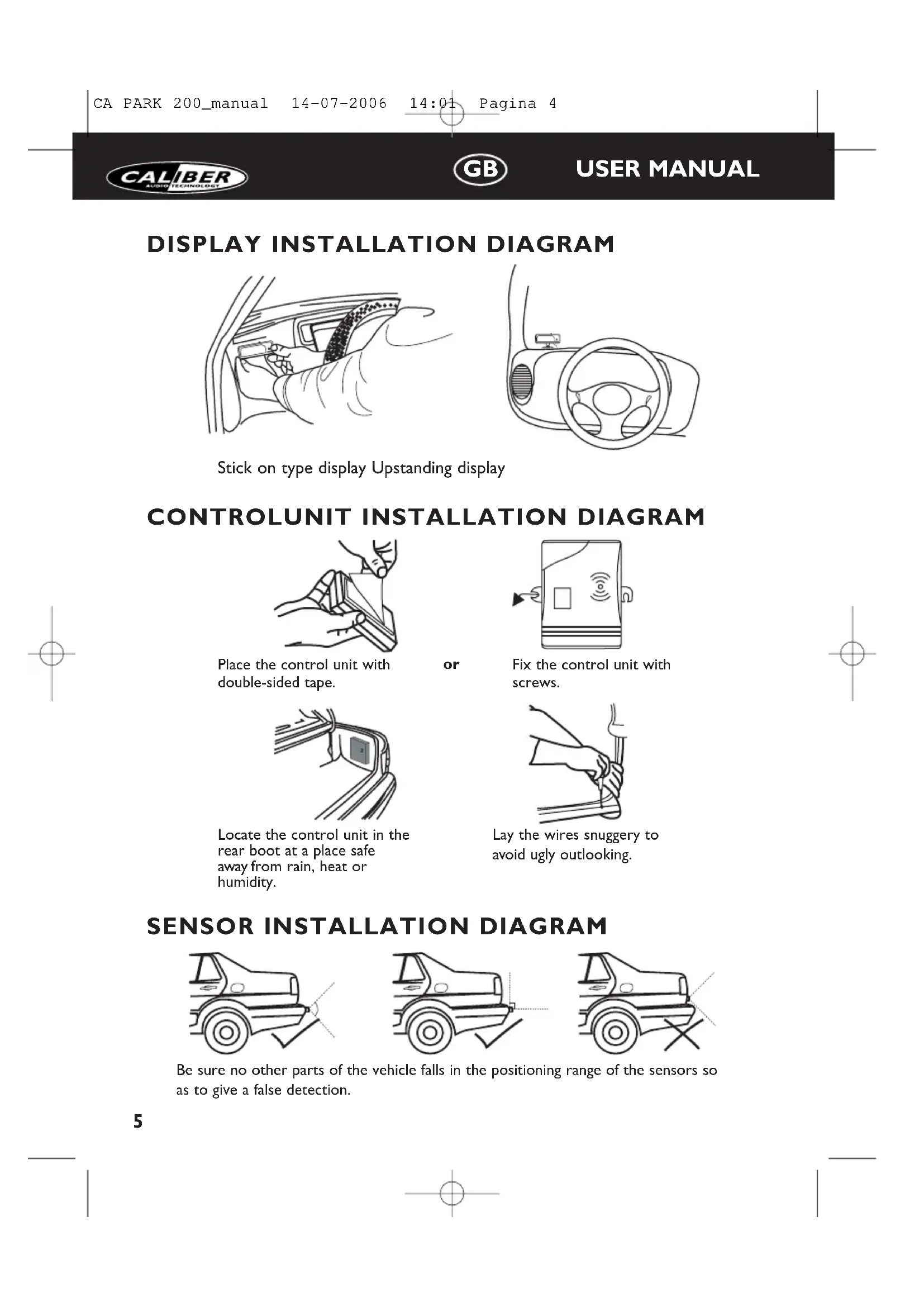
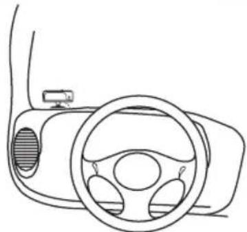
DISPLAY INSTALLATION DIAGRAM
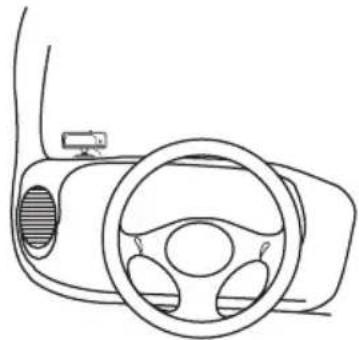
Stick on type display Upstanding display

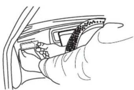
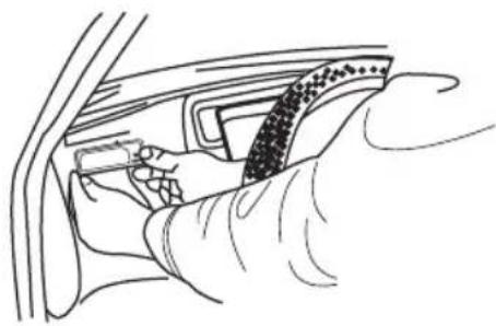
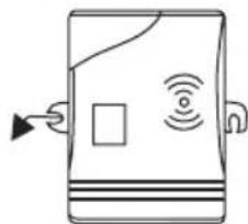
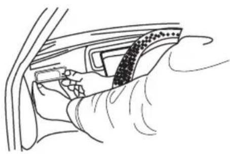
CONTROLUNIT INSTALLATION DIAGRAM
Place the control unit with double-sided tape.
or
Fix the control unit with screws.
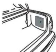
Locate the control unit in the rear boot at a place safe away from rain, heat or humidity.

Lay the wires snuggery to avoid ugly outlooking.
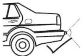
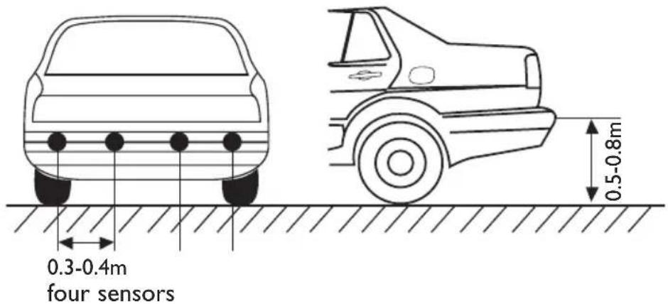
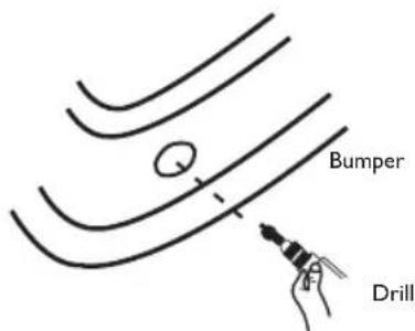
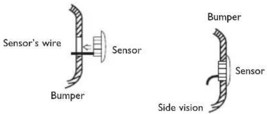
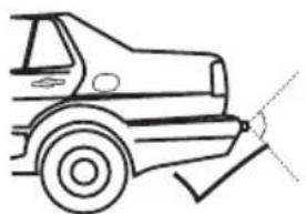
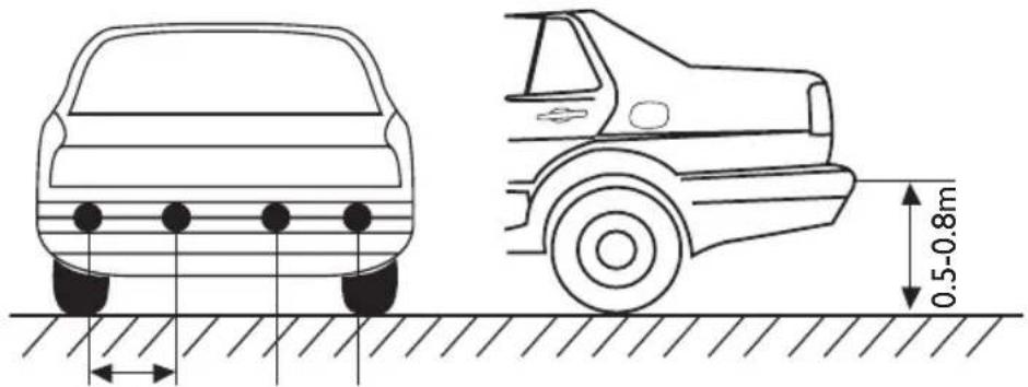
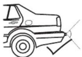
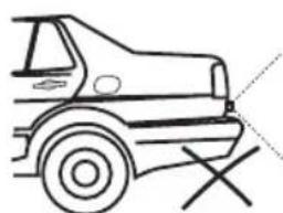
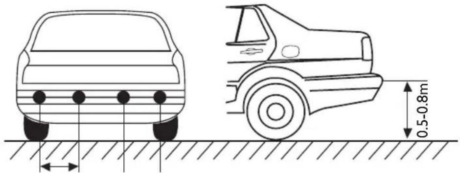
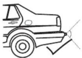
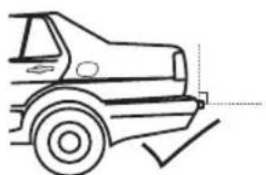
SENSOR INSTALLATION DIAGRAM

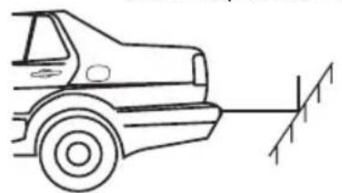
Be sure no other parts of the vehicle falls in the positioning range of the sensors so as to give a false detection.
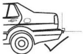
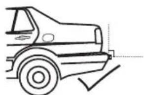
SENSOR INSTALLATION DIAGRAM
Be sure no other parts of the vehicle falls in the positioning range of the sensors so as to give a false detection.
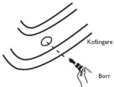
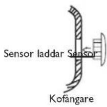
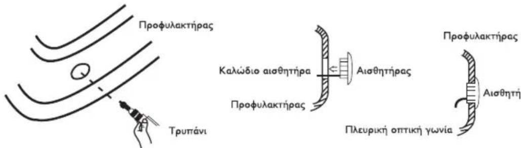
I.The sensor's wire must be protected from damage.
2. Holes have to be made to install insert-in sensors
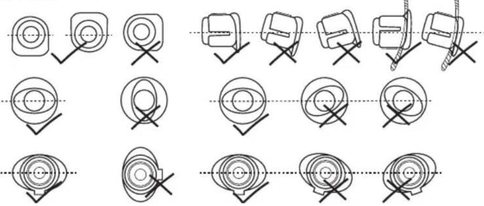
3. Make sure the sensors direction is correct
NOTES
INSTALL THE SYSTEM
- Position the sensors according the quantity and diagram I in page 6.
- Install the sensors, adjust the direction and arrange the wires in good order.
- Connect the red wire of the control unit with the positive wire of the reversing light, the black wire with the ground wire (or directly to the chassis of the car)
- Connect the display with the control unit, don't connect the sensors at this moment.
- Put the car into back gear, the backup light and the decimal point in the display will be lighted and give out a short beep, which show the system is in normal test status.
- Connect one sensor with the control unit and stand at the position of 1,0m in front of the sensor, the system detects and show the distance accordingly. Pull out the sensor and test the other sensors in the same way. After the test, connect all the sensors respectively to the control unit.
NOTE
I. Displays of same model could be interchanged, but the sensors are specially tuned for each control units;
2. In the normal situation, when the system detects anything in the dangerous range, it will give out long beep or red light to warn the driver, the car should be stopped immediately. The digital displays will not show the number when the distance is shorter than 0,3m.
3. Please be noted that the sensors should be installed properly.
4. The performance may be affected when the sensors are mounted in a metal bumper.
5. Do not install the sensors at the position easily affected by outer interference, such as the position close to exhaust pipe or other wires.
6. Please be sure that the engine isn't running while installing this system.
7. The performance may be affected in the following situation: Heavy rain or water inflow to the sensors;The gravel road, bumpy road, sloping road and bush;Very hot, cold or moist weather;The sensors covered by snow, ice, mud, etc.
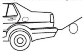
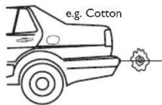
OBJECTS MAYBE CAUSE FAILURE DETECTION
Smooth slope Smooth round object Objects absorbing wave,
FAILURE HANDLING
A. If there were no sounds and light, please check and make sure that the wires were connected correctly, the voltage is not lower than 9V, whether the display was connected properly with the main unit.
B. If there were disordered display or continuous beep, please quit the reverse gear and then enter the reverse gear again, if there were still the same problems, the control unit is confirmed to be defective.
C. If the display gave long beep or showed 0.0m when the user test one of the sensors. Please check whether there are other parts of the vehicle falling into the detecting rage of the sensor being tested, whether the sensor was installed too tightly, whether the sensor was installed close to some strong trembling parts (such as exhaust pipe) of the car or whether there is some strong interference close to the sensor.
D. If the display show some numbers but there are no obstruction in front of the sensors, please check the direction of the sensors, maybe the system detects some parts of the vehicle.
E. If the display showed in a disorder way when gunning the engine, it is the circuit disturbing, please connect the system's ground wires with the vehicle's earth wire.
F.If the system still could not work properly after the above mentioned handling, the user can decide that the sensors don't match with the control unit, the whole system should be replaced.
APPENDIX
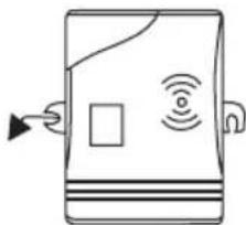
DISPLAY SPECIFICATION
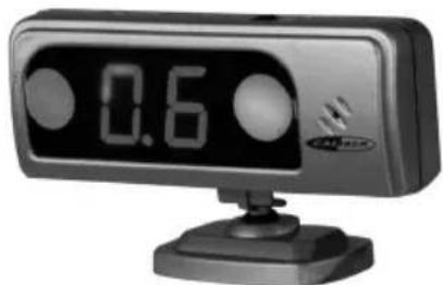
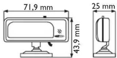
Alarm with three-step sounds, volume control available, numeric and right & left indicator with LED. Upstanding or adhesive styles optional.
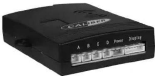
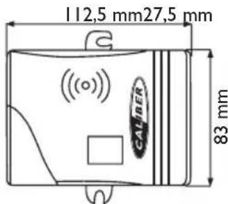
- CONTROL BOX
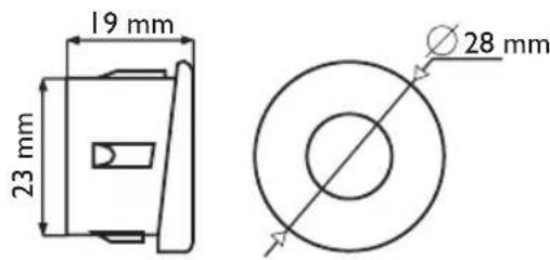
- SENSOR SPECIFICATION INSERT-IN TYPE SENSOR


PRINCIP DE SYSTEME
SON: BiBiBi (pas montants)
AFFICHAGE DE DISTANCE: 0.5 - 0.9m

Place the control unit with double-sided tape.
INSTALLATIONS DIAGRAM
SENSOR INSTALLATIONS DIAGRAM
SENSOR INSTALLATIONS DIAGRAM
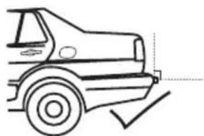
0.3-0.4m
Fyra sensorer
EMΦANISH ΔIAPAMMATO ΕΓΚATAΣΤΑΗΣ
Oboyn tuou Tou KoAAa
Opthia oovn
AIAPAMMA EKATAZTAHMONADAEAEXOY

TOnoTeTeIOTe Tn Movada
eEyxou Me Taivia Kofllnns
SInns oyns.
π ΘTEPEWOTMμováδa λEyxouμEβiδε

TOnoTeEIOTe Tm oVada
eIeyxou OTov Niow Xwpo
aTOOKEUW O EVA ONmu
aOaAeS MaKpia ano TN
BPOXn, Tn ZcOTn n Tny
Uypaia.

TOnotheTeIe ta kaLwSia
eapuotata wote va
aTOphiuyete TnV aoynm
ephiavion
AIAPAMMA ERKATAZTAZH2 AI2OHTHPA
BEgaophiaiote oIeV tha nefouv aaaa eapntmuata tou oxnatoS OTNV EMEAia tooepntncu w uonntnoy w sTu vay divouy auuaueu suotuau
AIAPAMMA EKATAZTAHSAIHOHTHPA
0.3-0.4m
Teoepic aioehtnpes
BEgaophiaiote oI 8ev 0a nfoov aaaa eapntmuata tou oxnmuotc otnv eueia toioeTmnc twv aoonnpw vtoi wote va sivouv laovv aoevo evtono.
- To kalωδio aiθηntjpa πρεπενa προστateuετal anó tη φθopa.
- Penei va yivovtal rpune yia thy Eykarataon twv aiOthnpwE kci eoc
- Egaphiaiote oti n kateuohuvon aothnpwv eival owotn.

∑HMEIΩΣEIS
CALIBER
GR
USER MANUAL
ERKATAZTAH TOY YYTHMATO
- TOnotheTeIeTOUc aIOoHTnpeC OuMwva ME mV NooTnTa KAI TO SIaYpaMa I OTN 62.
- EYkataotntote Touc aothnpes,puoioTe Tny kateuohvon kal opyavwote oWota ta KaWsi.
3 SuVoeTo Kokkivo KaWio Tns Movadac Eeyxou Me To Etiko KaWio Tns avTIOPOnLuxviac, To maipo KaWio ME To KaWio Yeiwns (n aneUeiaoc oT O Iaio Tou autokivntou) - Suovdeote mV oBovn me Tm moVada eXyou. Mny ouvdeote touc aoonnpes autn Tn OTiymu.
- BÁLTE IVIOW TAXUTNTA OTO autOKIVNTO, TO φως για στΙΟθΕV KAI TO δΕΚΑΒΙΚΟ Μημείον ΣΤΥ ΘΟΥ θΑ ανάψουν και θΑ εκπέμψουν εναύντοῦ ἡχο μπιπο OΤΟΙΟς θΑ δειξει ΠΤU ΣΟΥ ΜΑ βρισκεται ΕυσιλΟγική κατάστη Ελέγχου.
- Suvseote evav aothnpa me th movada eeyxou kai otaeite otn theon tou 1,0 m ptpoata an tov aothnpa, to ouotma avixveuei kal deixvei tv avtoioan no. TpaBnE tov aothnpa kai eeyte touc aalouc aothnpes me tov idio tpno. Meta tov eeyxo suvdeote olouc touc aothnpes avtiooixw os th movada eeyxou.
ΣHMEIΩΣH
- Oiofoves tou idou oovteauo npouv va avtalaoovtai, aia oiaonnpes exouv ouvtoviotei iikia yia kahe movada eEyxou.
- Tyn pfioaoyikn kataoataon otav to ouotma avixveuei OTIDNTNE TNY EIKivduvneEbeia, 0a EKTEmu eva pku npo o KOKivo Wc yia va Tpoedtonoei To v oy o To autokivto Ppnte va Otaatnoe ie aeooc
- OI i ofoe 0a 8iouv tov aioo oT av n aootaen eiva kpoepn ano 0.3 m. Iapakaoume one wote ot1 oaionnpes pntel va Eykataotaov ou
- H EKTÉLEON μIIOPEI VA EMTPEAOTEI OTAV OIAOHTNPTNEEVAL TOnoETNVEVOL OE EVAV EETAALIKO PPOΦUλAKTIPa.
- Mny Eyaotate Toua aonnpes ony then nooia empeaeetai ano eWtepik npaebaon onwcn then kovra orov owna Eaunnc n oe aa Kaawdia.
- NapaKaIoUe EaOaIaiote oTI O KIVNipac 8ev Aeioupyei Evw EYkaIOTATE TO ouTnua.
- H diaikaia o e i va empeaoTei kata nV akolouon kataoan: Meyaln Bpox n Eiopon vepou otous aiothntipes, dpoos me yapunai, avwuaoc 8pOoc, EIKivns 8pOoc kalayipoc 8pOoc, TLOU cEOTc, Kpuoc n UYPoc kaipoc, aiOHTpeTou KAunTovTai ME xlovi, naoy, AaONkA.
TA ANTIKEIMENA MNOPEI NA POKAENEOYN BAABH 2THN ANIXNEY

DISPLAY INSTALLATIE DIAGRAM
SENSOR INSTALLATIE DIAGRAM
- SENSOR SPECIFICATION INBOUW-SENSOR