GW90883 - Detector Gewiss - Free user manual and instructions
Find the device manual for free GW90883 Gewiss in PDF.

| Product type | KNX combined wind and rain sensor |
| Brand | Gewiss |
| Model | GW90883 |
| Dimensions (L × H × D) | 96 × 77 × 118 mm |
| Weight | 240 g |
| Power supply | 230 VAC, max. 20 mA |
| Bus power | KNX bus voltage |
| KNX bus consumption | 8 mA |
| Protection rating | IP44 |
| Wind measurement range | 0…70 m/s |
| Resolution | <10% of measured value |
| Accuracy | ±25% at 0…15 m/s |
| Number of communication objects | 81 |
| Max. group addresses | 254 |
| Max. allocations | 255 |
| Main functions | Rain detection, wind measurement, 4 switching outputs (3 wind + 1 rain), 8 AND gates and 8 OR gates |
| Operating temperature | -30…+50 °C |
| Mounting type | Surface or pole mounting |
| Housing | Plastic, white |
| Maintenance and cleaning | Check twice a year, clean with power off. Do not open in the rain. |
| Safety | Installation according to IEC 64-8 standard. Disconnect power before connection. Qualified personnel required. |
| Heater | 1.2 W |
Frequently Asked Questions - GW90883 Gewiss
User questions about GW90883 Gewiss
0 question about this device. Answer the ones you know or ask your own.
Ask a new question about this device
Download the instructions for your Detector in PDF format for free! Find your manual GW90883 - Gewiss and take your electronic device back in hand. On this page are published all the documents necessary for the use of your device. GW90883 by Gewiss.
USER MANUAL GW90883 Gewiss
SENSORE VENTO E PIOGGIA KNX KNX WIND AND RAIN SENSOR CAPTEUR DE VENT ET DE PLUIE KNX SENSOR DE VIENTO Y LLUVIA KNX WIND- UND REGENSENSOR KNX
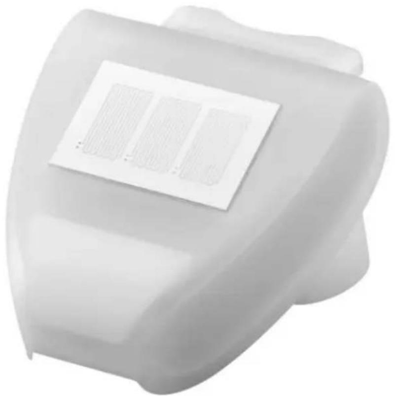
natural_image
White plastic mechanical component with a grid pattern on top (no text or symbols visible)
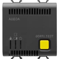
text_image
CE KNX®GW90883
1 AVVERTENZE GENERALI
text_image
Cross-sectional diagram of a multi-core cable with labeled components and directional arrowstext_image
Technical diagram of a mechanical component with labeled parts ① and ②natural_image
White plastic mechanical component with internal structure and directional arrows (no text or symbols)Dimensioni: 96 × 77 × 118 (L × H × P, mm)
Peso: 240 g
4.1 Warnings for KNX/EIB installation
4.2 Warnings for installation
4.3 Positioning
4.4 Fixing the support
4.5 View of the rear part, and perforation layout
4.6 Pre-arrangement of the sensor
4.7 Assembling the sensor
4.8 Tips for installation
5 PROGRAMMING
5.1 Application program
5.2 Programming the physical address
6 MAINTENANCE
7 TECHNICAL DATA
1 GENERAL WARNINGS
Attention!
The safety of the device is ensured only if the instructions given in this document are complied with.
Read them and keep them at hand.
The product must be installed in compliance with standard CEI 64-8
for devices for domestic use and similar, in non-dusty environments and where special protection against water penetration is not necessary.
The GEWISS sales organisation is available for any clarifications and technical information.
Gewiss S.p.A. reserves the right to make any necessary modifications to the product described in this manual, at any time and without forewarning.
2 PACK CONTENTS
The supply pack of the KNX wind and rain sensor contains the following components:
1 KNX wind and rain sensor device
2 metal hose clamps
1 installation manual
3 GENERAL DESCRIPTION
3.1 Briefly
The combined wind and rain sensor measures the wind speed and detects atmospheric precipitation (rain or snow, but not fog or dew) and communicates the values to the KNX system.
It has 3 output communication elements of the ON/OFF type that can be associated with three settable thresholds for wind speed, and 1 output communication element of the ON/OFF type for signalling the presence of precipitation; it also has additional AND/OR logic ports.
The device shell houses the sensors and the electronics for connecting the KNX BUS.
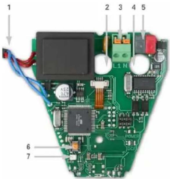
text_image
1 2 3 4 5 L1 N 6 7 POWER DCJ- Rain sensor connection cable assembled on the cover
- Opening for the 230V AC power supply cable
- Terminal for the 230V AC power supply; the terminals can be tightened for wires with a maximum section of 1.5 sq.mm.
- Opening for the KNX BUS cable
- KNX BUS terminal
- KNX push-button for programming
- KNX programming LED
3.2 Functions
- Rain detection: via the relative sensor, the device analyses the conductivity of the rainwater and immediately detects when the rain stops, thanks to the built-in heater.
- Wind measurement: wind intensity is measured electronically, in a quiet and reliable manner, even with hail, snow and sub-zero temperatures. The sensor also detects any air turbulence and thermal currents.
- Switchover outputs: 4 communication elements, 3 of which are associated with wind speed measurement and have settable thresholds (the threshold values can be set by means of parameters or communication elements).
- Logic operations: there are 8 AND ports and 8 OR ports, each supporting up to four inputs. The switchover values can be used directly as logic inputs. The output of each logic port can generate the sending of one communication item of 1 bit, or two items of 1 byte.
4 INSTALLATION

ATTENTION: the device must only be installed by qualified personnel, observing the current regulations and the guidelines for KNX/EIB installations.
4.1 Warnings for KNX/EIB installation
- The length of the BUS line between the KNX sensor and the power supply must not exceed 350 metres.
- The length of the BUS line between the KNX sensor and the furthest KNX/EIB device to be commanded must not exceed 700 metres.
- To avoid unwanted signals and overvoltages, do not create ring circuits.
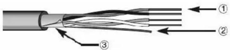
- Keep a distance of at least 4mm between the individually insulated cables of the BUS line and those of the electricity line.
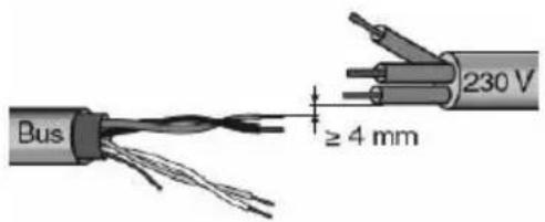
text_image
Bus ≥ 4 mm 230 V- Do not damage the electrical continuity conductor of the shielding.
text_image
Cross-sectional diagram of a cable showing three labeled components with directional arrows indicating flow or connection.- BUS cable
- Electrical continuity conductor
- Shielding
ATTENTION: the unused BUS signal cables, and the electrical continuity conductor, must never touch live elements or the earth conductor!
4.2 Warnings for installation
Installation, inspection, start-up, and troubleshooting operations on the sensor must only be carried out by qualified personnel.
The device is designed for a specific, appropriate use, and any inappropriate modification or failure to observe the user instructions will invalidate both the warranty and any claims.
The sensor must only be activated after being correctly assembled and after completing all the installation and start-up operations, and only within the sphere of its intended use.
Electric connections

ATTENTION: disconnect the mains supply before connecting the device to it!
For the electric connection layouts, refer to the examples below.
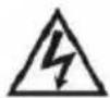
- Connect the red wire of the BUS cable to the red clamp (+) of the terminal, and the black wire to the black clamp (-).
Up to 4 BUS lines (wires of the same colour in the same clamp) can be connected to the BUS terminal.
text_image
Technical diagram of a mechanical component with labeled parts ① and ②- Connection of the BUS device
-
Connection of the BUS cable
-
Insulate the shield, the electrical continuity conductor, and the remaining white and yellow wires of the BUS cable (when using a 4-conductor BUS cable), as these are not needed.
4.3 Positioning
For the assembly, choose a place where the sensor can detect the wind intensity and atmospheric precipitation without any hindrance. There must be a space of at least 60cm below the sensor, to allow the wind to be measured correctly and to avoid any build-up of snow.
The area above the sensor must be free of any objects that could produce drips even after the rain has ended.
text_image
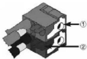
Wall or pole 90°The sensor must be assembled vertically, on a wall or pole.
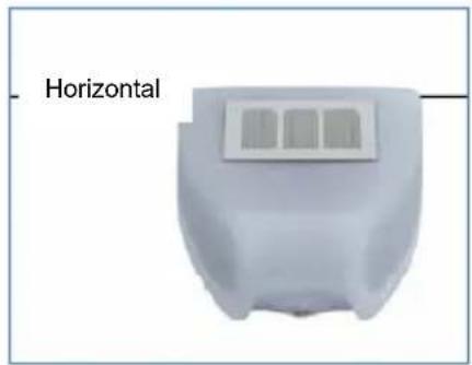
text_image
HorizontalThe sensor must be assembled horizontally.
4.4 Fixing the support
The sensor is supplied with a surface-mounting support.
Fix the support vertically on a wall or pole.
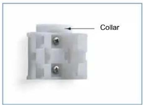
text_image
CollarSurface-mounting: the flat part on the wall, and the part with the protruding collar facing upwards.
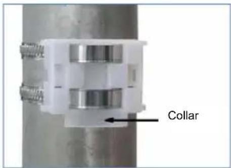
text_image
CollarPole-mounting: the curved part on the pole, and the collar facing downwards.
4.5 View of the rear part, and perforation layout
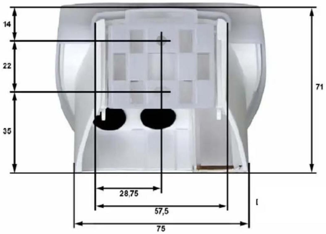
text_image
14 22 35 71 28,75 57,5 75Dimensions in mm
Dimensions of the rear part of the housing with bracket. Subject to improvement modifications.
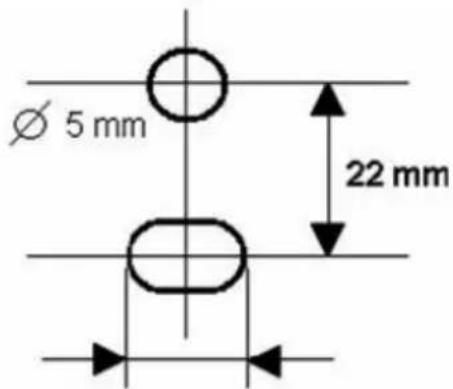
text_image
Ø 5 mm 22 mmPerforation layout
Slot 7.5 x 5mm
4.6 Pre-arrangement of the sensor
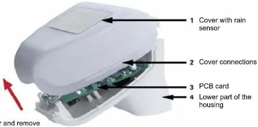
text_image
1 Cover with rain sensor 2 Cover connections 3 PCB card 4 Lower part of the housing and removeUnhook the cover and remove it by pulling upwards
The device cover has connections on the left and right, along the lower edge (see the figure).
Remove the cover carefully to avoid pulling the connection cable between the PCB card and the rain sensor assembled on the cover itself.
Push the power supply cable and the BUS connection through the rubber gasket on the sensor base, then connect the KNX BUS to the appropriate clamps.
4.7 Assembling the sensor
Close the housing by replacing the cover on the lower part.
The cover must be well inserted on both the right and the left (you should clearly hear a "click").
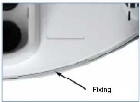
text_image
FixingCheck the cover and lower part are well locked together.
This figure shows the closed sensor from below.
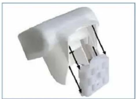
natural_image
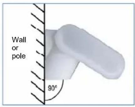
White plastic mechanical component with internal structure and directional arrows (no text or symbols)Push the housing down into the fixed support.
The protrusions on the support must clip into the housing guides.
4.8 Tips for installation
After powering the sensor, wait about 60 seconds before making a wind intensity reading and sending the switchover output value to the BUS.
5 PROGRAMMING
5.1 Application program
The application program can be downloaded from the website www.gewiss.com. Detailed information on the configuration parameters and their values is contained in the Technical Manual.
5.2 Programming the physical address
-
Power the device via the BUS.
-
Press the programming push-button to prepare the KNX sensor for the loading of the physical address from ETS.
To configure the device via ETS, both the main power supply and the KNX BUS power supply are needed.
6 MAINTENANCE
The sensor must be regularly checked (twice a year) for the presence of dirt, and cleaned if necessary. To remove the sensor, just pull it upwards (there will be some resistance from the fixing element). Do not open the sensor when it is raining, or in any case when water could get inside it: even just a few drops may damage the electronic system.

ATTENTION: for all maintenance and cleaning operations, disconnect the mains supply!
7 TECHNICAL DATA
Container: plastic material
Colour: white
Assembly: wall or pole
Degree of protection: IP44
Dimensions: 96 × 77 × 118 (L × H × D, mm)
Weight: 240g
Operating temperature: -30 ... +50°C
Power supply: 230V AC
Consumption: max. 20mA, with 10% ripple
BUS power supply: KNX BUS voltage
KNX BUS consumption: 8mA
Output data connector: KNX Standard
BCU type: included in the micro-controller
PEI type: 0
Group addresses: max. 254
Places: max. 255
Communication elements: 81
Heater: 1,2W
Wind sensor range: 0...70 m/s
Resolution: <10% of the measured value
Precision: ± 25% at 0...15 m/s, with an incidence angle of 45° on pole assembly
The following standards were taken into consideration when evaluating the electromagnetic compatibility of the product:
Transient emissions:
• EN 60730-1:2000 Section EMC (23, 26, H23, H26) (threshold category: B)
• EN 50090-2-2:1996-11 + A1:2002-01 (threshold category: B)
• EN 61000-6-3:2001 (threshold category: B)
Resistance to interference:
• EN 60730-1:2000 Section EMC (23, 26, H23, H26)
• EN 50090-2-2:1996-11 + A1:2002-01
• EN 61000-6-1:2004
The product has been tested on the basis of the above-mentioned standards, by an EMC-accredited laboratory.
FRANÇAIS
1 CONSIGNES GÉNÉRALES
2 CONTENU DE LA CONFECTION
3 DESCRIPTION GÉNÉRALE
3.1 Résumé
3.2 Fonctions
4 INSTALLATION
text_image
Cross-sectional diagram of a multi-core cable with labeled components and directional arrowstext_image
Technical diagram of a mechanical component with labeled parts ① and ②natural_image
Close-up of a white plastic spray gun component with black arrows indicating force or movement (no text or symbols visible)text_image
Cross-sectional diagram of a multi-core cable showing internal twisted insulation and insulation layers with numbered annotations.text_image
Technical diagram of a mechanical component with labeled parts ① and ②natural_image
White plastic mechanical component with internal structure and directional arrows (no text or symbols)Consumo bus KNX: 8mA
text_image
Cross-sectional diagram of a multi-core cable with labeled components and directional arrows- Buskabel
- Beidraht
- Schirm
text_image
Technical diagram of a mechanical component with labeled parts ① and ②natural_image
White plastic mechanical component with internal structure and directional arrows (no text or symbols)According to article 9 paragraph 2 of the European Directive 2004/108/EC and to article R2 paragraph 6 of the Decision 768/2008/EC, the responsible for placing the apparatus on the Community market is:
GEWISS S.p.A Via A. Volta, 1 - 24069 Cenate Sotto (BG) Italy Tel: +39 035 946 111 Fax: +39 035 945 270 E-mail: qualitymarks@gewiss.com


+39 035 946 111
8.30 - 12.30 / 14.00 - 18.00