
GW12716 - Detector Gewiss - Free user manual and instructions
Find the device manual for free GW12716 Gewiss in PDF.

| Product Type | Water Detector (H₂O) + RF Sensor |
| Brand | Gewiss |
| Model | GW12716 |
| Category | Detector |
| Detector Power Supply | 12 V AC/DC (+10%/-15%), 2 VA |
| Sensor Power Supply | 9 V Battery (not included) |
| Transmission Frequency | 868 MHz |
| Free Field Range | 100 m |
| Relay Output | 1 switching contact 2NO/1NC, 5A (AC1)/3A (AC15) - 250 V AC |
| Acoustic Alarm | Piezoelectric sounder, 70 dB at 1 m |
| Operating Temperature | +5°C to +40°C |
| Relative Humidity | 30% to 90% non-condensing |
| Detector Dimensions | 2 modules Chorus |
| Sensor Dimensions | 74 x 88 x 45.5 mm (W x H x D) |
| Max Number of Sensors | 5 |
| Battery Life | Approximately 1 year |
| Mounting | Flush-mount detector on Chorus support, wall-mounted sensor |
| Main Functions | Ultrasonic water detection, audible and visual alarm, solenoid valve control, remote control possible |
| Maintenance | Clean with a slightly damp cloth; do not open |
| Safety | Disconnect power before installation; installation by qualified personnel |
| Spare Parts | 9 V Battery, RF sensor |
Frequently Asked Questions - GW12716 Gewiss
User questions about GW12716 Gewiss
0 question about this device. Answer the ones you know or ask your own.
Ask a new question about this device
Download the instructions for your Detector in PDF format for free! Find your manual GW12716 - Gewiss and take your electronic device back in hand. On this page are published all the documents necessary for the use of your device. GW12716 by Gewiss.
USER MANUAL GW12716 Gewiss
GW 10 716 GW 12 716
GW 14 716
GW 12 718
L (+)
N (-)
12V ac/dc

flowchart
graph TD
    1["•"] --> A["A"]
    2["•"] --> A
    3["•"] --> B["B"]
    4["•"] --> B
2NA/1NC, 5A(AC1)/3A(AC15) - 250V ac
natural_image
Technical line drawing of an electronic device assembly showing internal components and casing (no text or symbols)
Led giallo.
verde
Programmazione.
natural_image
Pure diagram of a mechanical or electrical component with curved lines and shaded areas, no text or symbols present.natural_image
Diagram of a brick wall with curved arrows indicating direction, no text or symbols presentnatural_image
Diagram showing light rays reflecting off a curved surface with dashed circular paths (no text or symbols)natural_image
Floor plan diagram with black X-shaped cross symbol indicating restriction or exclusion (no text or labels)Errato
natural_image
Floor plan diagram with concentric dashed circles and black square markers (no text or labels)Corretto
Attention - Important
- Thank you for selecting this Gewiss product.
Gewiss products have been designed with attention to detail and built using only the very best materials.
Gewiss products will guarantee excellent and lasting performance.
- The installer is kindly requested to fill out this leaflet and then hand it to the end user, asking that he/she carefully read it.
- Carefully read the instructions below as they provide important information on how the water detector works, how it should be fitted and serviced (routine and extraordinary maintenance).
- The manufacturer may not be held liable for injury to persons or pets or damage caused by the use of the water detector in situations and conditions other than those indicated in the instructions below.
- The manufacturer may not be held liable in the case that the detector is sold in non-original packaging.
Immediately after removing the product from its packaging, make sure that it is not damaged.
- Make sure that the main power supply has been switched off before attempting to fit the device or touching the wiring.
- Before connecting the detector, make sure that the data on its ratings plate match the mains supply.
- Connect the detector as indicated in the drawings on page 33.
- All Chorus products must be fitted in compliance with CEI 64-8 standards for domestic appliances and similar devices, in dust-free areas and where there is no need for special water-proofing protection.
- Always contact an authorised technician or Gewiss's own customer service ("SAT") if the detector is faulty and/or malfunctions and in the case of extraordinary maintenance and scrapping.
CONTENTS
INTRODUCTION
- Functions 28
INSTALLATION INSTRUCTIONS
- Detector features 29
- RF sensor features 30
- Terminal description 32
- Connection diagrams 33
- Detector assembly.... 34
- Sensor assembly 35
USER INSTRUCTIONS
- Control description 36
- Light signals 37
- Operating modes and signals.... 39
- Prescriptions for correct use.... 42
- Advice on positioning 42
- Signal transmission examples 43
- Area of coverage 44
Functions
The water presence detection system consists of an inset detector and a wall sensor in radio frequency at the frequency of 868 MHz.
The water sensor detects the presence of water by operating using ultrasounds.
This technology prevents oxidation of the contacts due to humidity and therefore avoids untimely interventions.
The Chorus flood protection system for domestic use allows users to:
- handle one or more water detectors using an RF connection.
- detect the presence of water by installing sensors.
- the use of an internal relay to trigger a solenoid valve with manual reset to intercept the delivery of the water at the point of supply.
- signalling the alarm by means of an audible warning and a light signal.
Water detector features
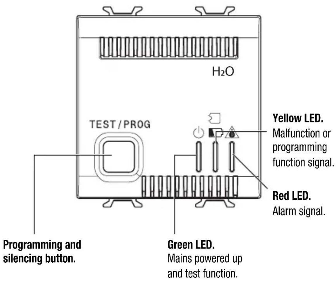
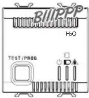
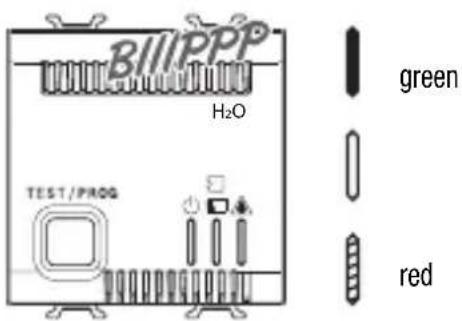
The detector is fitted with an RF system for receiving signals transmitted by the sensors. On the front there is a programming button, 3 indication LEDs and a buzzer for audible signals. Output relay with hermetic contacts for solenoid valve control. (or other electric supply e.g. a pump)
TECHNICAL DATA
• Power supply 12V ac/dc +10/-15%
- Power absorbed 2VA
- Audible alarm 70 dB at 1 m piezoelectric audible warning for alarm
- Output relay one switched contact 2NO/1NC, 5A(AC1)/3A(AC15) - 250V ac
- Operating temperature from +5°C to +40°C
- Ambient relative humidity +30÷90% without condensation
- Fixing inset on Chorus support
• Detector dimensions 2 Chorus modules
STANDARDS REFERENCES
• EN 60065, EN 55014-1; EN 55014-2.
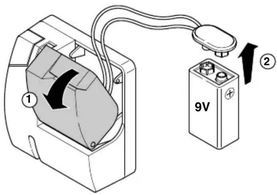
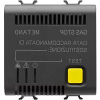
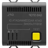
RF sensor features
The sensor is equipped with:
- A button: this is used by the detector during the sensor acquisition phase (PROGRAM-MING), during the operating check phase (TEST) or to cancel possible alarms.
Pressing the key on the sensor during the TEST phase must be rapid, while during the PROGRAMMING phase the key must be kept pressed for at least 5 seconds. - LED: this shows the operating status and remains on for a few seconds during FLOODING ALARM and SENSOR PRESENT transmissions, blinking for signalling BATTERY FLAT.
The power supply is provided by a 9V battery (not included in the pack) with a life of approximately 1 year.
To optimize the sensor's autonomy, the liquids present search operation and the immediate transmission of the alarm signal to the detector is done at 2 minute intervals.
In the worst case, therefore, the alarm is generated within a maximum of 2 minutes from the instant the sensor detects the presence of liquids.
The sensor sends the following information relative to its status to the detector:
- Alarm: during this transmission the LED on the sensor switches on for a few seconds.
- Sensor presence + sensor faulty or battery flat: this information is transmitted to the receiver every 12 hours.
INSTALLATION INSTRUCTIONS
RF sensor features
Button
(worked from above)
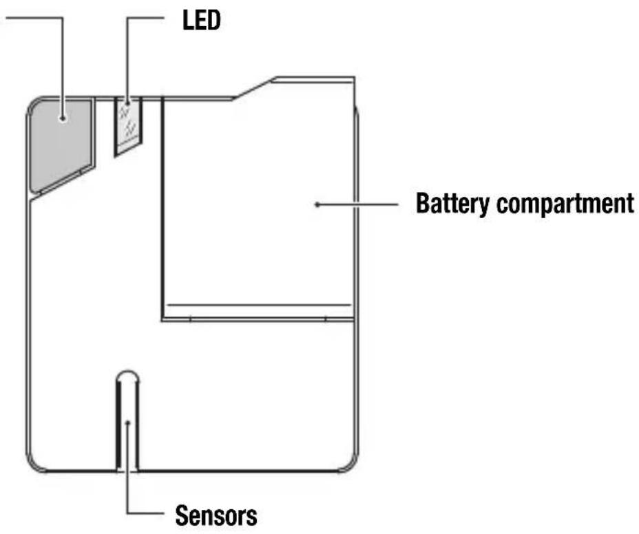
- Sensor dimensions 74x88x45,5 mm (BxHxP)
• Transmission frequency 868 MHz
• Capacity in free field 100 mt
• Power supply 9V battery
INSTALLATION INSTRUCTIONS
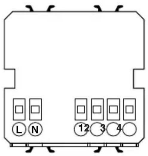
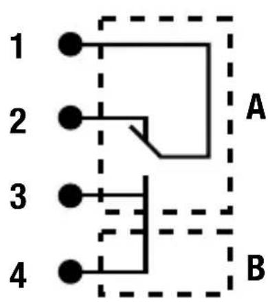
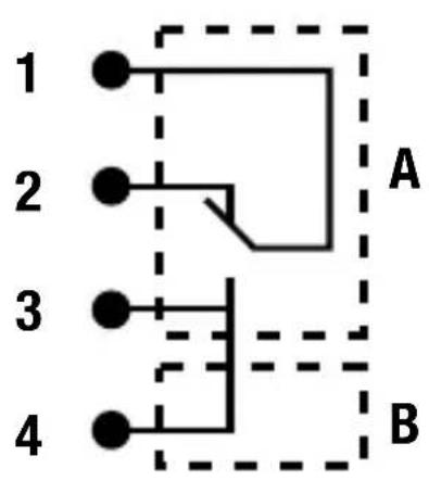
Description of the water detector clamps
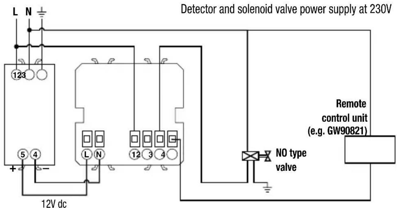
The detector can be connected to the 230V - 50 Hz mains (when required) using a 230V ac - 12V dc power supply module (GW 10 719, GW 12 719 e GW 14 719).
L (+)
N (-)
12V ac/dc

flowchart
graph TD
    1["●"] --> A["A"]
    2["●"] --> A
    3["●"] --> B["B"]
    4["●"] --> B
    style A fill:#fff,stroke:#000
    style B fill:#fff,stroke:#000
2NA/1NC, 5A(AC1)/3A(AC15) - 250V ac
A Potential-free contact to be used for controlling a solenoid valve with manual reset (NO or NC).
B Supplementary NO contact for a local and/or remote signalling function.
The installation and electrical connection of the devices and appliances must be done by qualified personnel and in conformity with the standards and laws in force.
The manufacturer declines all and any responsibility concerning the use of products that must follow specific environmental and/or installation standards, the responsibility for which remains at the competence and charge of the installer.
The examples given in this documentation are of principle; scrupulously comply with the laws and standards in force for the connection operations.
Warning: Power down the mains supply before installing the product
INSTALLATION INSTRUCTIONS
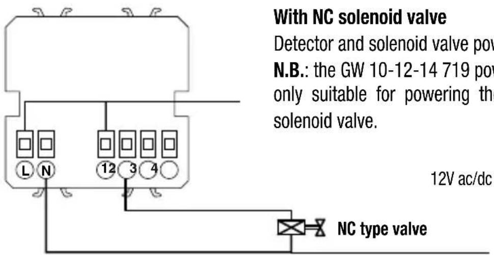
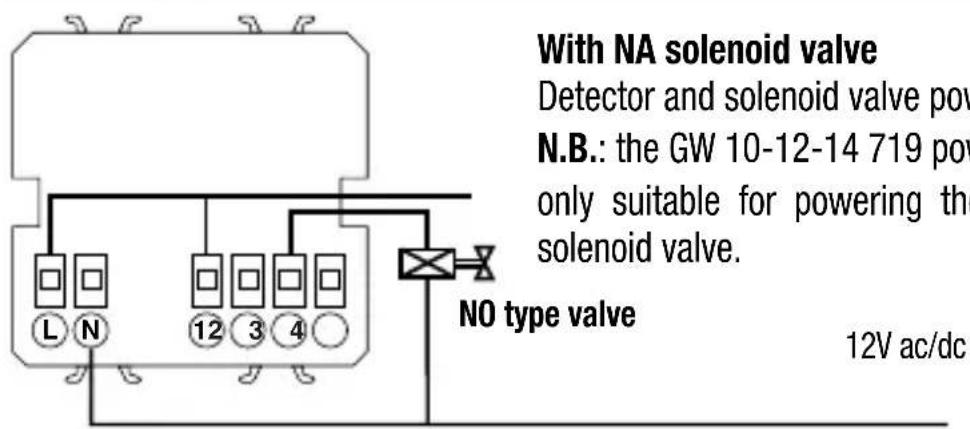
Connection diagrams
INSTALLATION INSTRUCTIONS
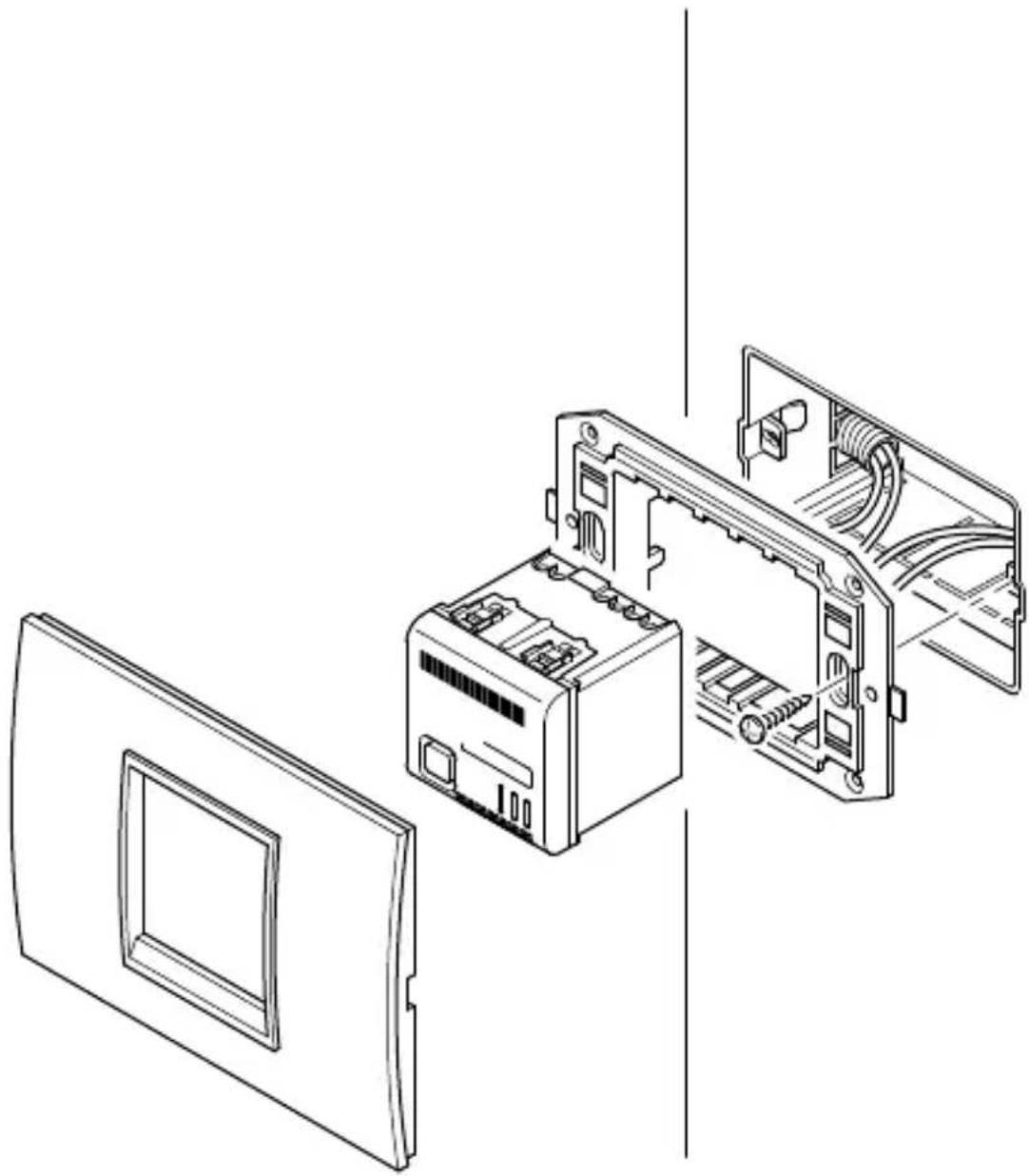
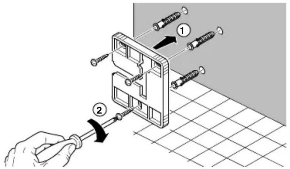
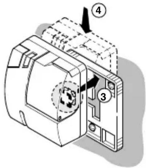
Detector assembly
natural_image
Exploded view diagram of an electronic device showing internal components and casing (no text or symbols)The detector must be installed on Chorus supports (minimum 2 modules) and completed with finishing plaques (ONE, LUX or ART).
INSTALLATION INSTRUCTIONS
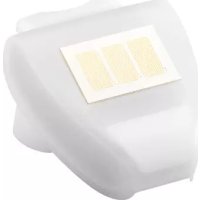
Sensor assembly
The sensor must be positioned flush with the floor so that it can detect the presence of liquids, in such a position that the LED is well visible and the button accessible. Before definitively fixing the sensor to the wall it is advisable to check the RF connection with the detector.
To do this requires carrying out the sensor acquisition procedure and a test from the position where the sensor will be installed (see following paragraphs).
Double fixing possibility:
From above 3-4 From left-hand side 3-4
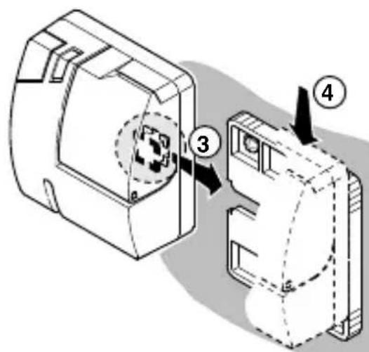
NOTE: The first time the product is powered-up or when the “sensor-detector” communication is particularly DIFFICULT, it is recommended to check during installation that sensor and detector communicate properly (see “faulty sensor test and identification” procedure).
USER INSTRUCTIONS
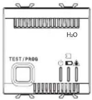
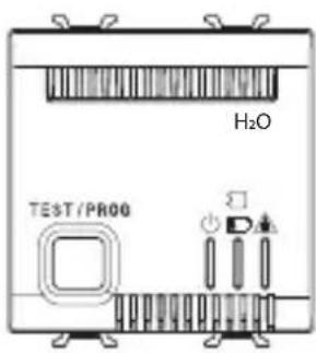
Control description
USER INSTRUCTIONS
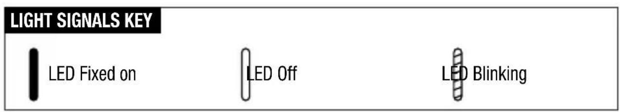
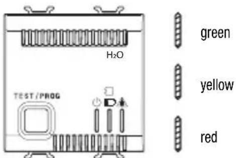
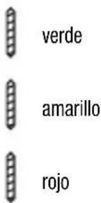
Light signals

green
Detector powered up and in normal operating conditions.

green

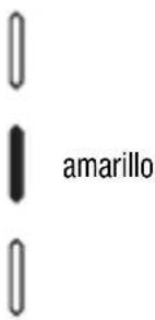
yellow
In the case of a fault, malfunction or flat battery in a sensor, the yellow LED blinks and an intermittent audible alarm is activated until it is silenced by pressing the front button or the fault is resolved.

green

[Non-Text]
Test.
The green LED blinks after prolonged pressure of the front button for approximately 5 seconds.
Light signals
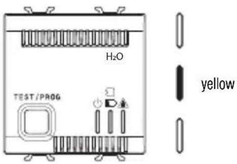
Programming.
Pressing the button for approximately 5 seconds during the "test" phase causes a move to the programming phase.
Detector cut-out.
Rapidly pressing the button disables the detector. The detector returns into service when the button is pressed again or automatically after a time interval of 24h.
The operation is useful for avoiding false alarms in cases of maintenance or in cases of cleaning the room.
Alarm.
On arrival of the alarm signal from a sensor the audible alarm is activated and the red LED blinks.
In the case of an alarm it is necessary to identify the reason that has caused it and act accordingly.
Operating modes and signals
The presence of power and therefore operation of the detector is shown by the green LED fixed on.
If there is no power the detector will not work, but all the parameters remain stored.
The system restarts automatically when power is restored.
SENSOR ACQUISITION
To access sensor acquisition mode the detector's key must be kept pressed for 5 seconds so that the green LED blinks (TEST function); press the key again for another 5 seconds so that the yellow LED comes fixed on (PROGRAMMING function).
Keep the button on each sensor pressed for approximately 5 seconds to send the identification code to the detector: an audible signal (short but strident) signals successful reception by the sensor.
The maximum number of sensors that can be installed is 5.
To end the PROGRAMMING phase and return to operating mode press the detector button (where 5 sensors are configured, the programming phase is automatically exited as soon as you have completed the last configuration).
The absence of signals or commands for more than 3 minutes causes automatic exit from the PROGRAMMING function.
It is not possible to insert the same sensor more than once.
Whenever the PROGRAMMING phase is accessed, all the sensors present are cancelled and the acquisition operation must be repeated for all the sensors.
FAULTY SENSOR TEST AND IDENTIFICATION
To identify a faulty sensor (namely one that does not transmit) or to check the efficiency of the system, the TEST function must be accessed by keeping the detector's key pressed for 5 seconds (the green LED will blink).
Then press the single buttons present on the sensors in succession: if the sensor is perfectly operational the detector outputs an audible signal of successful reception, no signal is output if the sensor is faulty or with a flat battery.
The absence of signals or commands for more than 3 minutes causes automatic exit from the TEST function.
Operating modes and signals
FLAT BATTERY ALARM AND ITS RESETTING
The flat battery situation is signalled both by the LED (on the sensor) blinking until the battery is replaced and by the yellow LED on the detector blinking and the simulta-neous output of a slight and intermittent sound signal (buzzer type) that can only be silenced by the key on the detector itself.
The detector's yellow LED will continue to blink, even after silencing, until the battery is replaced.
To reset the battery flat alarm after battery replacement, it is necessary to make a test of the sensor in the alarm situation by accessing the TEST function or waiting a maximum of 6 hours for automatic reset.
Operating modes and signals
SENSOR FAULTY ALARM AND ITS RESETTING
The sensor sends a presence signal every 12 hours.
If the detector does not receive the signal, the yellow LED starts to blink and the buzzer outputs a slight and intermittent sound (buzzer type) that can only be silenced by the key on the detector itself.
To identify the faulty sensor and subsequently to reset the alarm (after having reset the device), it is necessary to make a test of the sensor in the alarm situation by accessing the TEST function or waiting a maximum of 6 hours for automatic reset.
If the faulty sensor has to be replaced, it is necessary to reacquire all the sensors (PROGRAMMING function).
FLOODING ALARM AND ITS RESETTING
The detector in alarm situation is signalled by the blinking of the red LED and the output of an acute and prolonged sound with an intensity of approximately 70dB.(reading taken at 1 metre).
The output relay is excited by switching its NO/NC contacts.(and therefore the solenoid valve is closed).
The alarm is silenced by pressing the key on the detector.
After silencing, only the visual signal remains (red LED blinking) and the relay contact remains closed for as long as the sensor continues to detect the presence of water.
If the flooding alarm is never silenced, the buzzer will continue to sound at maximum for 3 minutes while the relay and blinking red LED remain active for as long as there is the presence of water.
REMOTE CONTROL
To send an alarm SMS, use a GW 90 821 remote control unit.
Please refer to the remote control instruction manual for connection procedures.
USER INSTRUCTIONS
Prescriptions for correct use
- Do not open or tamper with the appliance: danger of electric shock and malfunctioning.
- Only use a slightly damp cloth for cleaning the appliance.
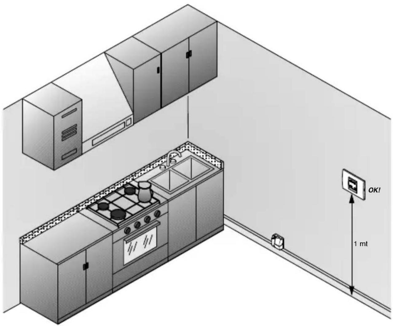
Advice on positioning
The Chorus water detectors must be installed about 1 metre from the floor (standard height for control devices).
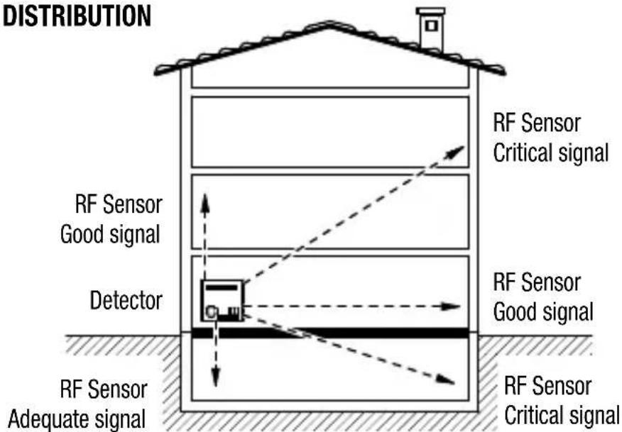
Signal transmission examples
• RF Sensor capacity (in free-field conditions)
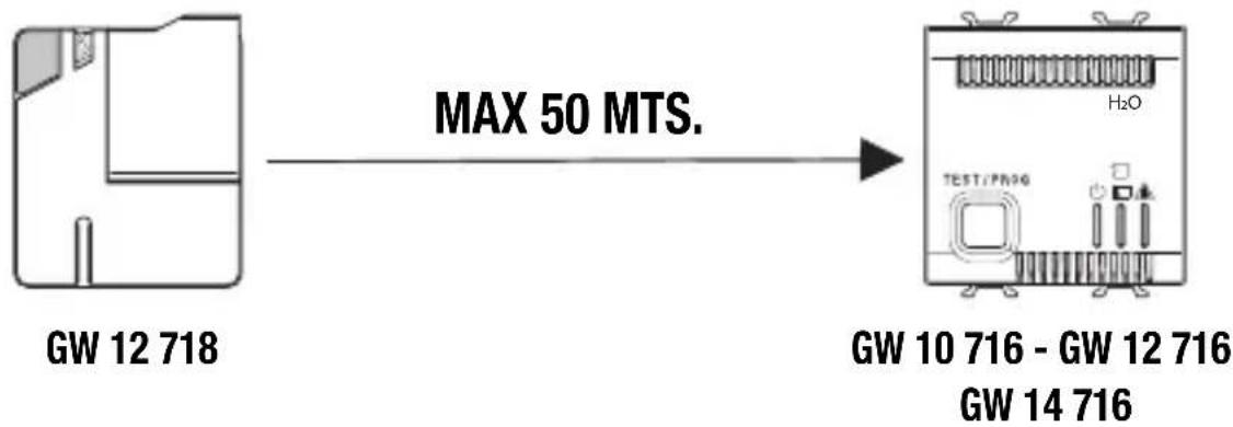
flowchart
graph LR
    A["GW 12 718"] -->|MAX 50 MTS.| B["GW 10 716 - GW 12 716"]
    B --> C["GW 14 716"]
WARNING:
When installing the various detectors it is important to check the correct wireless range capacity for each sensor towards the detector.
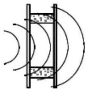
Decreased and critical wireless signal level with regards to different building materials:
with walls in plywood, plasterboard or hollow panelling ...
natural_image
Pure diagram of a mechanical or electrical component with curved lines and shaded areas, no text or symbols present....range of full capacity from 100% to 90%
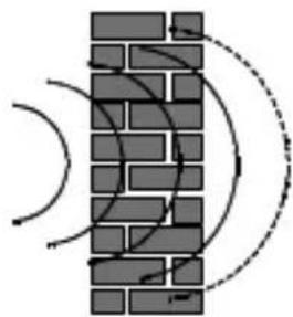
with walls in brick or perforated blocks...
natural_image
Diagram of a brick wall with curved arrows indicating direction, no text or symbols present...range of full capacity from 95% to 65%
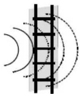
with walls in reinforced concrete
natural_image
Diagram showing light rays reflecting off a curved surface with dashed circular paths (no text or symbols)...range of full capacity from 70% to 10%
USER INSTRUCTIONS
Area of coverage
Layouts, examples and useful advice for the installation and handling of the devices
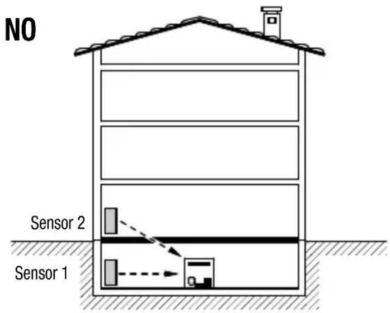
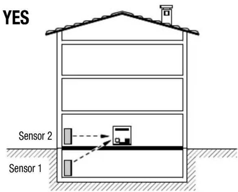
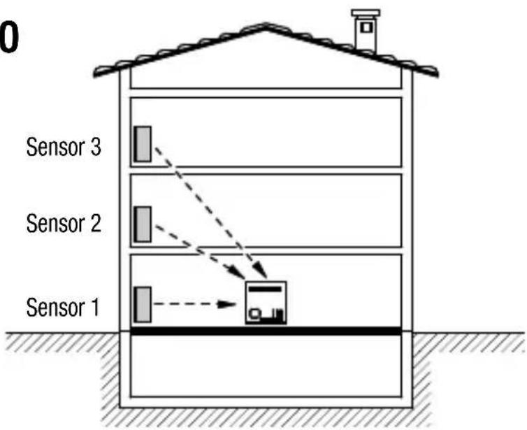
In the event the system is split on different floors, do not install the detector in the basement.
USER INSTRUCTIONS
Area of coverage
NO
YES
In the event the system is split on different floors, try to position the detector on the vertical of the sensors.
Area of coverage
Layouts, examples and useful advice for the installation and handling of the devices.
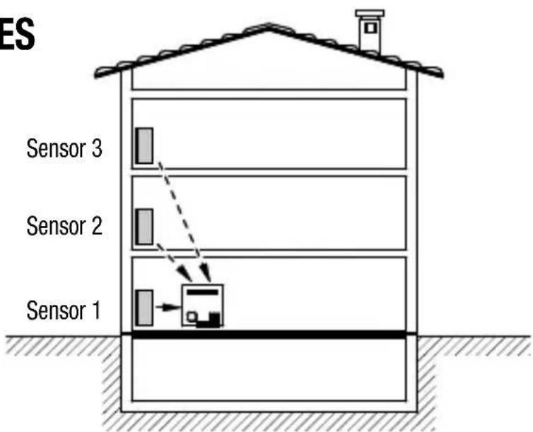
VERTICAL DISTRIBUTION
SOLUTION 1
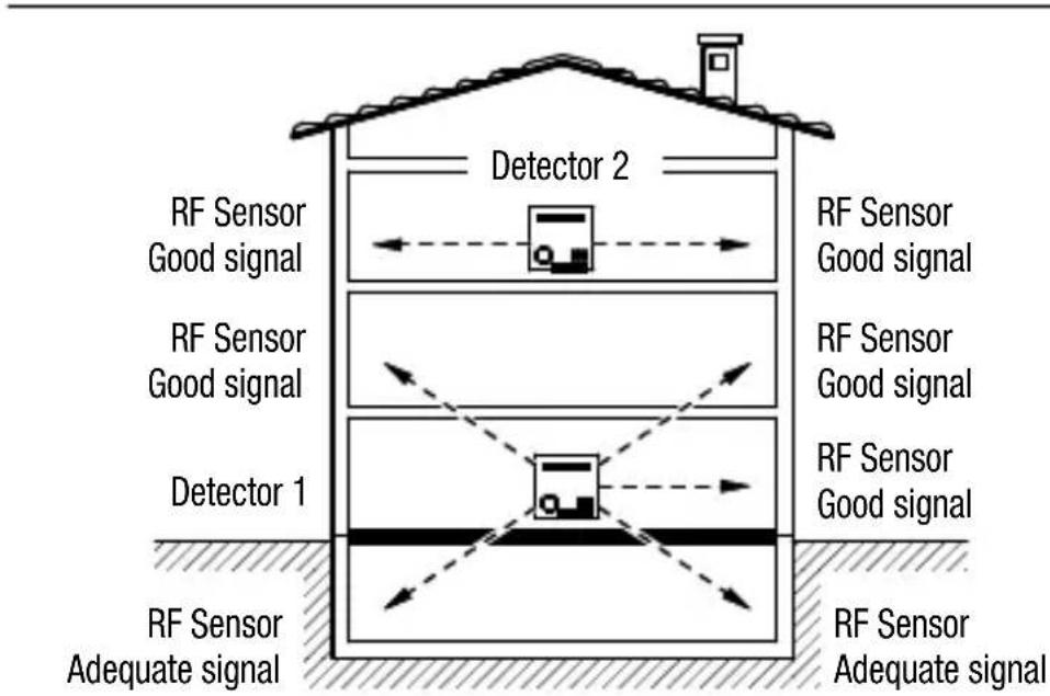
SOLUTION 2
NOTE: In a system made with several RF sensors connected to one detector only, check the correct communication between the devices; should one or more sensors have some trouble in the communication with the detector, it is advisable to install further detectors in the house in order to ensure a proper coverage (solution 2).
USER INSTRUCTIONS
Area of coverage
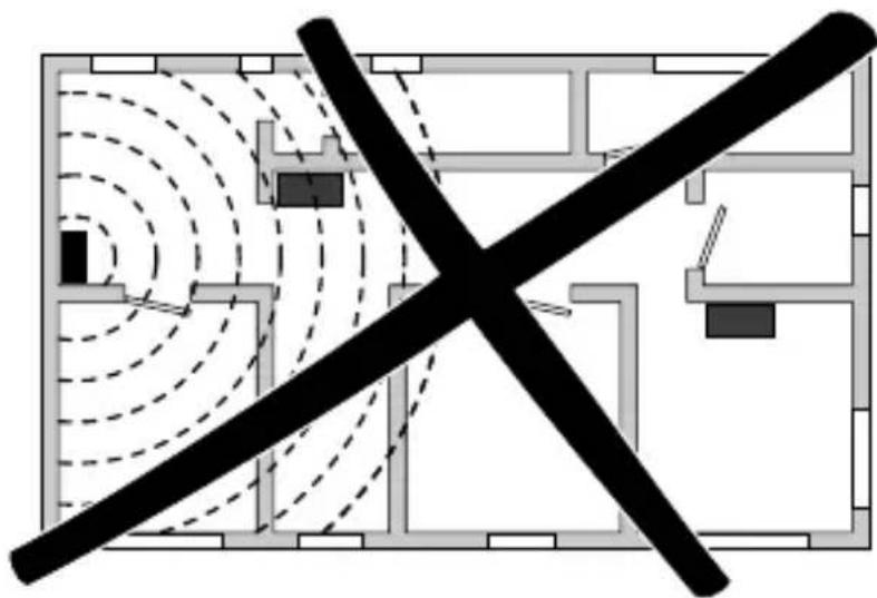
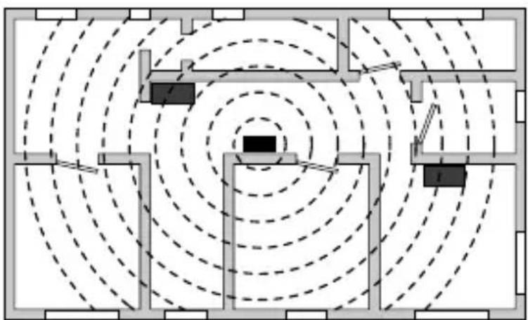
HORIZONTAL DISTRIBUTION
natural_image
Architectural floor plan with black X-shaped cross symbol indicating restriction or exclusion (no text or labels)Wrong
By installing the detector in a decentralised position the sensors located in the opposite side of the house may be too far and may not be able to send a good signal due to the architectural and/or structural impediments.
natural_image
Floor plan diagram with concentric dashed circles and rectangular blocks (no text or labels)Correct
By installing the detector in a barycentric position in respect to the sensors, the distance between the devices decreases, thus improving communication.
FRANÇAIS
Attention - Important
L (+)
N (-)
12V ca/cc
flowchart
graph TD
    1["1"] --> A["A"]
    2["2"] --> A
    3["3"] --> B["B"]
    4["4"] --> B
2NO/1NF, 5A(AC1)/3A(AC15) - 250V ca
natural_image
Technical line drawing of an electronic device assembly showing internal components and casing (no text or symbols)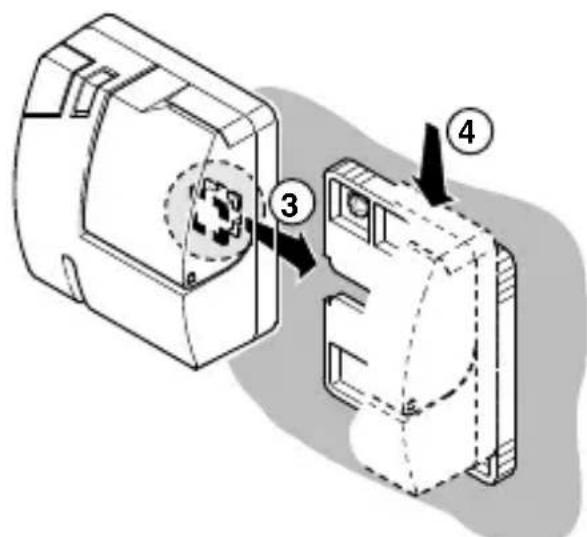
Led jaune.

INSTRUCTIONS D'UTILISATION
natural_image
Pure diagram of a mechanical or optical setup with curved lines and layered components (no text or symbols)natural_image
Diagram of a brick wall with curved arrows indicating direction and motion, no text or symbols presentnatural_image
Diagram showing light rays reflecting off a curved surface with dashed circular paths (no text or symbols)natural_image
Floor plan diagram with black X-shaped cross symbol indicating no crossing or intersection (no text or labels)Erroné
natural_image
Floor plan diagram with concentric dashed circles and rectangular structures (no text or labels)Correct
L (+)
N (-)
12V ac/dc
flowchart
graph TD
    1["●"] --> A["A"]
    2["●"] --> A
    3["●"] --> B["B"]
    4["●"] --> B
    style A fill:#fff,stroke:#000
    style B fill:#fff,stroke:#000
2NA/1NC, 5A(AC1)/3A(AC15) - 250V ac
natural_image
Technical line drawing of an electronic device assembly showing internal components and casing (no text or symbols)
Led amarillo.

verde
Programación.
ISTRUCCIONES DE EMPLEO
natural_image
Pure diagram of a vertical structure with curved arrows indicating direction, no text or symbols presentnatural_image
Diagram of a brick wall with curved arrows indicating direction, no text or symbols presentnatural_image
Diagram showing light rays reflecting off a curved mirror or lens system (no text or symbols)natural_image
Architectural floor plan with black X-shaped cross symbol indicating restriction or exclusion (no text or labels)Erróneo
natural_image
Floor plan diagram with concentric dashed circles and rectangular blocks (no text or labels)Correcto
L (+)
N (-)
12V ac/dc

flowchart
graph TD
    1["•"] --> A["A"]
    2["•"] --> A
    3["•"] --> B["B"]
    4["•"] --> B
2 NO/1 NG, 5A(AC1)/3A(AC15) - 250V AC
Mit Magnetventil NG
Mit Magnetventil NO
natural_image
Technical line drawing of an electronic device assembly showing internal components and casing (no text or symbols)

BEDIENUNGSANWEISUNG
natural_image
Pure diagram of a vertical structure with curved lines and shaded regions, no text or symbols present.natural_image
Diagram of a brick wall with curved arrows indicating direction, no text or symbols presentnatural_image
Diagram showing light rays reflecting off a curved mirror (no text or symbols)natural_image
Architectural floor plan with a black X-shaped cross symbol indicating a restriction or exclusion zone (no text or labels present)Falsch
natural_image
Floor plan diagram with concentric dashed circles and rectangular blocks (no text or labels)Richtig
In compliance with the laws in force, this product, at the end of its life span, must be disposed of separately from urban waste (as shown by the “crossed bin” on the product). Therefore, at the end of its life span, the user must take the product to an appropriate differentiated collection centre or give it to the retailer when a new product is bought. Differentiated collection is indispensable for limiting the potential impact on the Environment and Health caused by incorrect disposal of electric and electronic appliances at the end of their life. Gewiss takes an active part in operations encouraging the correct reuse, recycling and recovery of electric and electronic appliances. Contact the local waste disposal service or the product's retailer for further information.
According to article 9 paragraph 2 of the European Directive 2004/108/EC and to article R2 paragraph 6 of the Decision 768/2008/EC, the responsible for placing the apparatus on the Community market is:
GEWISS S.p.A Via A. Volta, 1 - 24069 Cenate Sotto (BG) Italy Tel: +39 035 946 111 Fax: +39 035 945 270 E-mail: qualitymarks@gewiss.com


+39 035 946 111
8.30 - 12.30 / 14.00 - 18.00

- 2NA/1NC, 5A(AC1)/3A(AC15) - 250V ac
- Led giallo.
- Programmazione.
- Errato
- Corretto
- Attention - Important
- CONTENTS
- INTRODUCTION
- INSTALLATION INSTRUCTIONS
- USER INSTRUCTIONS
- Functions
- Water detector features
- TECHNICAL DATA
- STANDARDS REFERENCES
- RF sensor features
- Button
- Description of the water detector clamps
- Connection diagrams
- Detector assembly
- Sensor assembly
- Control description
- Light signals
- Test.
- Programming.
- Detector cut-out.
- Alarm.
- Operating modes and signals
- SENSOR ACQUISITION
- FAULTY SENSOR TEST AND IDENTIFICATION
- FLAT BATTERY ALARM AND ITS RESETTING
- SENSOR FAULTY ALARM AND ITS RESETTING
- FLOODING ALARM AND ITS RESETTING
- REMOTE CONTROL
- Prescriptions for correct use
- Advice on positioning
- Signal transmission examples
- WARNING:
- Area of coverage
- HORIZONTAL DISTRIBUTION
- Wrong
- Correct
- FRANÇAIS
- 2NO/1NF, 5A(AC1)/3A(AC15) - 250V ca
- Led jaune.
- INSTRUCTIONS D'UTILISATION
- Erroné
- Led amarillo.
- Programación.
- ISTRUCCIONES DE EMPLEO
- Erróneo
- Correcto
- NO/1 NG, 5A(AC1)/3A(AC15) - 250V AC
- Mit Magnetventil NG
- Mit Magnetventil NO
- BEDIENUNGSANWEISUNG
- Falsch
- Richtig
Brand : Gewiss
Model : GW12716
Category : Detector