GW90740A - Smart Home Gewiss - Free user manual and instructions
Find the device manual for free GW90740A Gewiss in PDF.

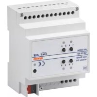
| Product Type | 4-channel 16 AX KNX actuator for DIN rail |
| Brand | Gewiss |
| Model | GW90740A |
| Category | Smart Home |
| Power supply | KNX bus (10 mA max) |
| Number of channels | 4 |
| Relay type | 16 AX, potential-free NO contact |
| Max switching current | 16 A (AC1) |
| Max power incandescent lamp | 3000 W |
| Max power halogen lamp | 3000 W |
| Max power toroidal transformer | 3000 W |
| Max power electronic transformer | 2000 W |
| Max power low energy lamp | 80 x 23 W |
| Max dissipated power | 4 W |
| Operating temperature | -5 to +45 °C |
| Storage temperature | -25 to +70 °C |
| Max relative humidity | 93 % (non-condensing) |
| Protection degree | IP20 |
| Dimensions (W x H x D) | Approx. 70 x 90 x 64 mm (4 DIN modules) |
| Weight | Approx. 200 g |
| Mounting | 35 mm DIN rail |
| Electrical connections | Removable screw terminals, max cross-section 4 mm² |
| Bus connection | 2-pin plug-in terminal ∅ 1 mm |
| Main functions | ON/OFF switching, timing, scenarios (8/output), priority commands, AND/OR logic functions, lock |
| Configuration | ETS software |
| Maintenance | No maintenance required, clean with a dry cloth |
| Safety | Installation by qualified personnel, compliance with standards EN50428, EN50090-2-2 |
| Certification | CE (low voltage and EMC directives) |
Frequently Asked Questions - GW90740A Gewiss
User questions about GW90740A Gewiss
0 question about this device. Answer the ones you know or ask your own.
Ask a new question about this device
Download the instructions for your Smart Home in PDF format for free! Find your manual GW90740A - Gewiss and take your electronic device back in hand. On this page are published all the documents necessary for the use of your device. GW90740A by Gewiss.
USER MANUAL GW90740A Gewiss
text_image
A ① ② N.O. L OUT1 L N.O. OUT2 ④ ③ ⑧ ⑦ ⑥ ⑤ ⑨ ⑩ ⑫ ⑪ OUT3 N.O. L OUT4 L N.O. ⑬ ⑭ ⑮ ⑯ ⑰ ⑱ ⑲ ⑳ ⑮ ⑯ ⑰ ⑱ ⑲ ⑳ ⑮ ⑯ ⑰ ⑱ ⑲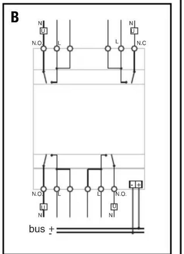
text_image
B N U N.O. L L N.C N.O. L L N.O. N N bus +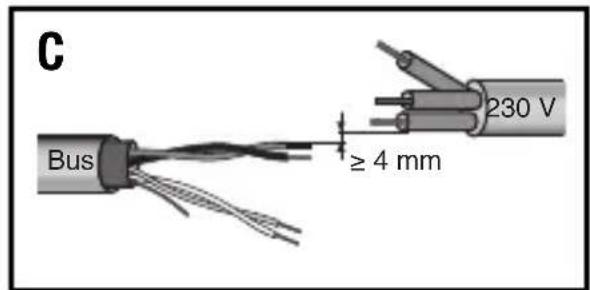
text_image
C Bus ≥ 4 mm 230 V① Uscita relè 1 - Output relay 1 - Sortie relais 1 - Salida relé 1 - Relaisausgang 1
② Uscita relè 2 - Output relay 2 - Sortie relais 2 - Salida relé 2 - Relaisausgang 2
③ Pulsante comando locale relè 1 - Relay 1 local command button - Bouton-poussoir de commande locale du relais 1 - Pulsador mando local de relé 1 - Lokaler Relaissteuertaster 1
④ LED stato relè 1 - Relay 1 status LED - LED état du relais 1 -LED de estado de relé 1 - LED Relaisstatus 1
⑤ Pulsante comando locale relè 2 - Relay 2 local command button - Bouton-poussoir de commande locale du relais 2 - Pulsador mando local de relé 2 - Lokaler Relaissteuertaster 2
⑥ LED stato relè 2 - Relay 2 status LED - LED état du relais 2 - LED de estado de relé 2 - LED Relaisstatus 2
⑦ LED stato relè 3 - Relay 3 status LED - LED état du relais 3 - LED de estado de relé 3 - LED Relaisstatus 3
⑧ Pulsante comando locale relè 3- Relay 3 local command button - Bouton-poussoir de commande locale du relais 3 - Pulsador mando local de relé 3 - Lokaler Relaissteuertaster 3
⑨ LED di programmazione indirizzo fisico - LED for programming physical address - LED de programmation de l'adresse physique - LED de programación de dirección física - LED für die Programmierung der physikalischen Adresse
⑩ Tasto di programmazione indirizzo fisico - Button key for programming physical address - Touche de programmation de l'adresse physique - Tecla de programación de dirección física - Taste für die Programmierung der physikalischen Adresse
⑪ Pulsante comando locale relè 4 - Relay 4 local command button - Bouton-poussoir de commande locale du relais 4 - Pulsador mando local de relé 4 - Lokaler Relaissteuertaster 4
⑫ LED stato relè 4 - Relay 4 status LED - LED état du relais 4 - LED de estado de relé 4 - LED Relaisstatus 4
⑬ Uscita relè 3 - Output relay 3 - Sortie du relais
3 - Salida relé 3 - Relaisausgang 3
⑭ Uscita relè 4 - Output relay 4 - Sortie du relais
4- Salida relé 4 - Relaisausgang 4
⑮ Terminali bus - Bus terminals - Bornes du bus- Conectores bus - Busanschlüsse
INDICE
text_image
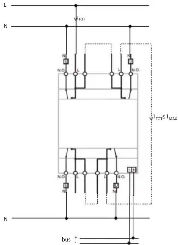
L N V1TOT N N.O. L L N.O. I_TOT≤I_MAX N.O. L L N.O. N N bus + -AVVERTENZE GENERALI
2004/108/CE, EN50428, EN50090-2-2
PROGRAMMING WITH ETS SOFTWARE.... 18
TECHNICAL DATA 19
If the dual terminals are used for phase (L) entry and exit, check that the total circulating current ( I_TOT ) does not exceed the max current ( I_MAX ) indicated in the "Technical data" section of the instruction sheet.
text_image
L N V_TOT N N.O. L L N.O. N.O. I_TOT≤I_MAX N.O. L L N.O. N bus + -GENERAL WARNINGS
Warning! The safety of this appliance is only guaranteed if all the instructions given here are followed scrupulously.
These should be read thoroughly and kept in a safe place.
Chorus products can be installed in environments which are dust-free and where no special protection against the penetration of water is required.
They shall be installed in compliance with the requirements for household devices set out by the national standards and rules applicable to low-voltage electrical installations which are in force in the country where the products are installed, or, when there are none, following the international standard for low-voltage electrical installations IEC 60364, or the European harmonization document HD 60364.
Gewiss sales organization is ready to provide full explanations and technical data on request.
Pack Contents
n. 1 KNX 4-channel 16 AX actuator - DIN rail mounting
n. 1 Bus terminal
n. 4 Screw terminals
n. 1 Cover with screw
n. 1 User and installation manual
Briefly
The KNX 4-channel 16 AX actuator—DIN rail mounting allows up to 4 different electrical loads to be activated/deactivated separately by means of 4 x 16 AX relays, each one fitted with 1 NO output contact. The relay switchover command can come from command devices or sensors of the Building Automation system via the KNX bus or generated locally via the front push-buttons.
The actuator is powered from the BUS line and is equipped with 4 front green LEDs for signalling the output status. The device sends information to the bus about the relay status (ON = contact closed, OFF = contact open) when switching on, receiving a command and in the case of a command from a local push-button.
Each output channel of the actuator can be configured separately and allows the ON/OFF command of the controlled loads, execution of timed commands, scene management and execution of priority commands to force the output status. The functioning modes can be used simultaneously by means of distinct communication objects.
This means, for instance, that the device can switch a light on and off, or automatically switch it on and off after a certain pre-established time, simply on the basis of the command received.
The module is assembled on the DIN rail, inside the electric boards or junction boxes.
Functions
The actuator is configured with the ETS software to create the functions listed below.
Switchover:
- parameterisation of output behaviour (NO/NC)
- timing of stair lights and the possibility of setting its duration via the BUS
- timing of stair lights with switch-off warning function
- delayed activation/deactivation
- blinking
Scenes:
- memorisation and activation of 8 scenes (value 0 - 63) for each output
- enabling/disabling storing of scenes by the BUS
Priority commands:
- parameterisation of the output relay value at the end of forcing
Blocking command:
- parameterisation of the blocking object value and output relay value at the end of blocking
Safety functions:
- periodical monitoring of input object
Logical functions:
- AND/NAND/OR/NOR logical operation with command object (switchover, timed switchover, delayed switchover, blinking) and result of the logical operation
- using the result of the logical operation to enable the command object (switchover, timed switchover, delayed switchover, blinking, scene)
- logic operations AND/NAND/OR/NOR/XOR/XNOR up to 4 logic inputs
Output status:
- parameterisable sending to the BUS
Other functions:
- parameterisation of output behaviour with voltage fall/reset on BUS
- parameterisation of behaviour of local command push-buttons
INSTALLATION
ATTENTION: the device must only be installed by qualified personnel, observing current regulations and the guidelines for KNX installations.
Recommendations for installing the KNX
- The length of the bus line between the aduator and the power supply must not exceed 350m metres.
- Thelen gth of the bus line between the actuator and the furthest way KNX device must not exceed 700 metres.
- To avoid unwanted signals and overvoltages do not usering circuits.
- Keep a distance of at least 4mm between the individually in insulated cables of the bus line and those of the electricity line (figure C).
- Do not damage the electrical continuity conductor of the shielding (figure D).
ATTENTION: The bu ssignal cable sthat are not used and the electrical continuity conductor must never touch any live elements or the ear rhin g conductor!
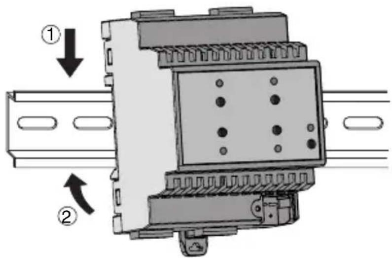
Assembly on the DIN rail
Mount the 4-channel actuator on a 35mm DIN rail in the following way (figure E):
- Insert the upper device coupling in the DIN rail.
- Turn the device and lock it on the DIN rail, using the fixing tab
Electric connections
ATTENTION: disconnect mains voltage before connecting the device to the mains!
Figure B shows a diagram of the electrical connections.
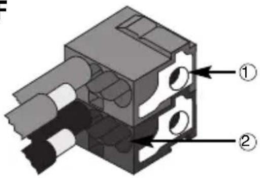
- Connect the red wire of the bus cable to the red terminal (+) of the terminal and the black wire to the black terminal (-). Up to 4 bus lines can be connected to the bus terminal (same coloured wires on the same terminal) (figure F).
- Insulate the shield, the electrical continuity conductor and the other white and yellow wires of the bus cable (if a 4-conductor bus cable is being used), that are not necessary (figure D).
- Insert the bus terminal in the device's pins. The correct insertion direction is determined by the fixing guides. Insulate the bus terminal with the cover to be screwed onto the device.
The cover guarantees the minimum separation distance of 4mm between the power cables and the bus cables (figure G). - Connect the loads to the relevant supplied screw terminals, making sure the current limits specified in the Technical Data are not exceeded. Insert the terminals in the actuator output connectors, and check they are correctly inserted (figure H).
Using the local command push-button
With the local command push-buttons (figure A) you can control cyclic ON/OFF switching over, reversing the status of the relay each time it is pressed (default setting). If a priority command is active, the local commands will not be executed. It is possible to configure the behaviour of the local command push-button via ETS
ATTENTION: the local command push-buttons will only work if BUS voltage is present.
Maintenance
The device does not require any maintenance. Use a dry cloth if cleaning is required.
PROGRAMMING WITH ETS SOFTWARE
The device must be configured with the ETS software.
Detailed information about the configuration parameters and their values can be found in the Technical Manual
TECHNICAL DATA
Communication KNX Bus
Power supply via the KNX bus, 29 V dc SELV
Bus cable KNX TP1
Bus current consumption 10 mA max
Command elements 1 miniature programming key
4 push-buttons for local relay command
Display elements 1 red programming LED
4 green LEDs for signalling output status
Actuation elements 4 16AX relays with NO potential free contact
Maximum switchover current 16 A (AC1)
16AX (140 F ref. EN 60669-1) fluorescent loads
with maximum surge current 400A (200 μs)
Maximum power for load type Incandescent lamps (230 V AC): 3000W
Halogen lamps (230V AC): 3000W
Loads controlled by toroidal transformers: 3000W
Loads controlled by electronic transformers: 2000W
Low consumption lamps
(compact fluorescent lamps): 80x23W
Maximum dissipated power 4W
Ambit of use Indoors, dry places
Operating temperature -5 to +45 °C
Storage temperature -25 to +70 °C
Relative humidity Max 93% (non condensative)
Bus connection Coupling terminal, 2 pins ∅ 1 mm
Electrical connections Extractable screw terminals, maximum cable section: 4mm^2
Protection ratings IP20
Dimension 4 DIN modules
Reference standard Low voltage directive 2006/95/EC
Electromagnetic Compatibility Directive
2004/108/EC, EN50428, EN50090-2-2
Certifications KNX/EIB
SOMMAIRE
CONSIGNES GÉNÉRALES ...... page 22
DESCRIPTION GENERALE 23
INSTALLATION 25
PROGRAMMATION AVEC LOGICIEL ETS 27
DONNEES TECHNIQUES 28
text_image
L N V1TOT N N.O. L L N.O. N I_TOT ≤ I_MAX N.O. L L N.O. N N bus +CONSIGNES GÉNÉRALES
PROGRAMMATION AVEC LOGICIEL ETS
Communication Bus KNX
Alimentation Par bus KNX, 29 V cc SELV
Câble bus KNX TP1
Certifications KNX/EIB
ÍNDICE
pag. ADVERTENCIAS GENERALES.... 31
text_image
L N V̇TOT N N.O. L L N.O. N.O. I_TOT ≤ I_MAX N.O. L L N.O. N bus + -2004/108/CE, EN50428, EN50090-2-2
text_image
L N V_TOT N N.O. L L N.O. N.O. I_TOT ≤ I_MAX N.O. L L N.O. N bus + -ALLGEMEINE HINWEISE
Halogenlampen (230VAC): 3000W
2004/108/EG, EN50428, EN50090-2-2
text_image
Cross-sectional diagram of a multi-core cable showing internal twisted insulation and insulation layers with numbered annotations.① Cavo bus - Bus cable - Câble bus - Cable bus - Buskabel
② Conduttore di continuità elettrica - Electrical continuity conductor - Conducteur de continuité électrique - Conductor de continuidad eléctrica - Stromdurchgangsleiter
③ Schermatura - Shielding - Blindage - Blindaje - Abschirmung
E
text_image
Technical diagram of a mechanical assembly with labeled components and directional arrows indicating motion or assembly.F
text_image
Technical diagram of a mechanical assembly with labeled parts ① and ②① Connessione dispositivo bus
Bus device connection - Connexion dispositif bus - Conexión dispositivo bus Anschluss Busvorrichtung
natural_image
Technical diagram of a mechanical assembly with ports and a directional arrow (no text or symbols)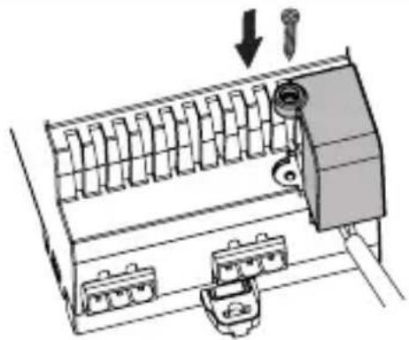
natural_image
Diagram of a mechanical device with ports and a screw, showing no text or symbols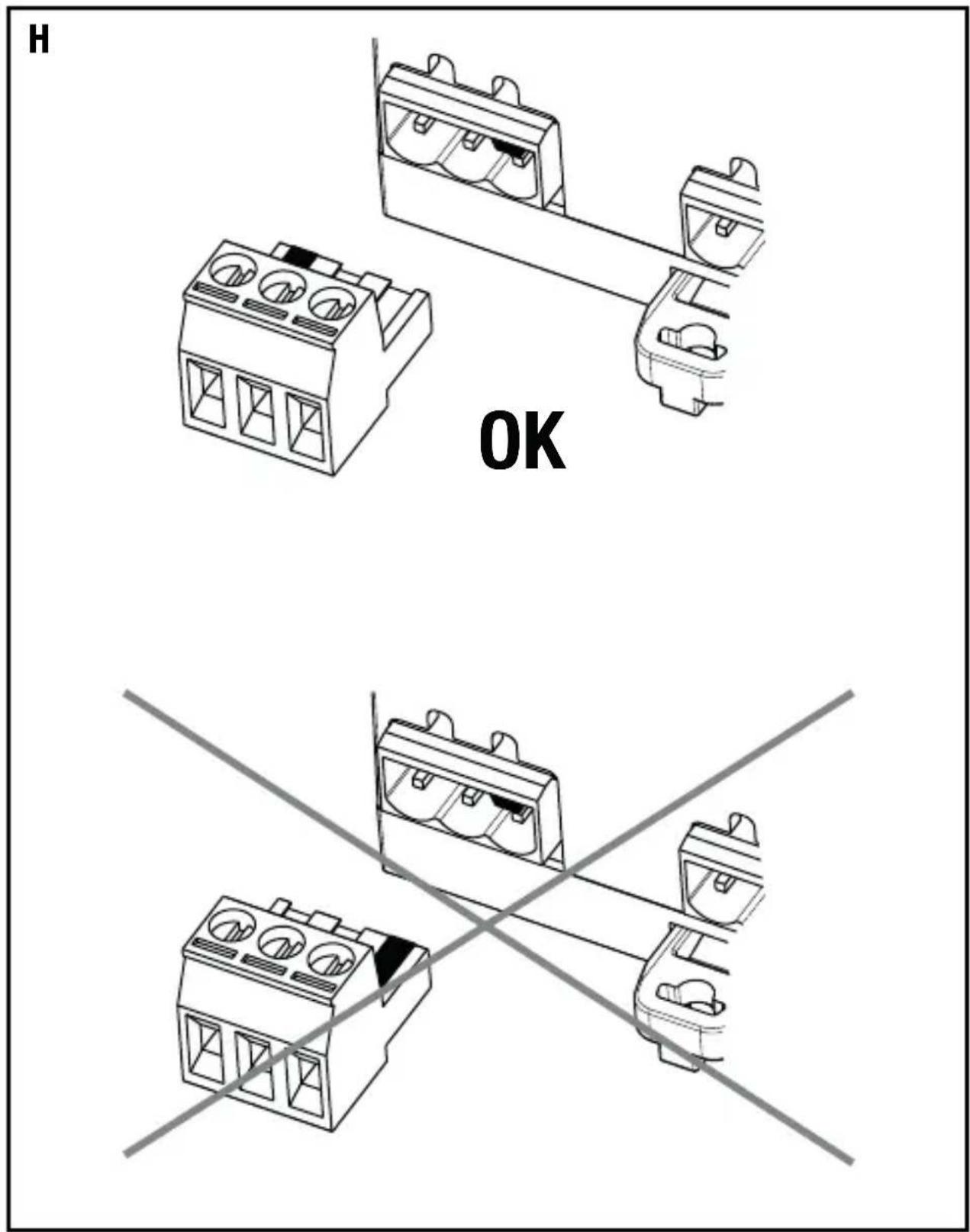
text_image
H OKAccording to article 9 paragraph 2 of the European Directive 2004/108/EC and to article R2 paragraph 6 of the Decision 768/2008/EC, the responsible for placing the apparatus on the Community market is:
GEWISS S.p.A Via A. Volta, 1 - 24069 Cenate Sotto (BG) Italy Tel: +39 035 946 111 Fax: +39 035 945 270 E-mail: qualitymarks@gewiss.com


+39 035 946 111
8.30 - 12.30 / 14.00 - 18.00