GW14776 - Smart Home Gewiss - Free user manual and instructions
Find the device manual for free GW14776 Gewiss in PDF.
Frequently Asked Questions - GW14776 Gewiss
User questions about GW14776 Gewiss
0 question about this device. Answer the ones you know or ask your own.
Ask a new question about this device
Download the instructions for your Smart Home in PDF format for free! Find your manual GW14776 - Gewiss and take your electronic device back in hand. On this page are published all the documents necessary for the use of your device. GW14776 by Gewiss.
USER MANUAL GW14776 Gewiss
Warning! The safety of this appliance is only guaranteed if all the instructions given here are followed scrupulously. These should be read thoroughly and kept in a safe place. The Chorus products must be installed in compliance with the requisites of standard CEI 64-8 for devices for domestic use and similar, in non-dusty atmospheres and where special protection against water penetration is not required.
The GEWISS sales organisation is at your disposal for clarifications and technical information.
Gewiss SpA reserves the right to make changes to the product described in this manual at any time and without giving any notice.
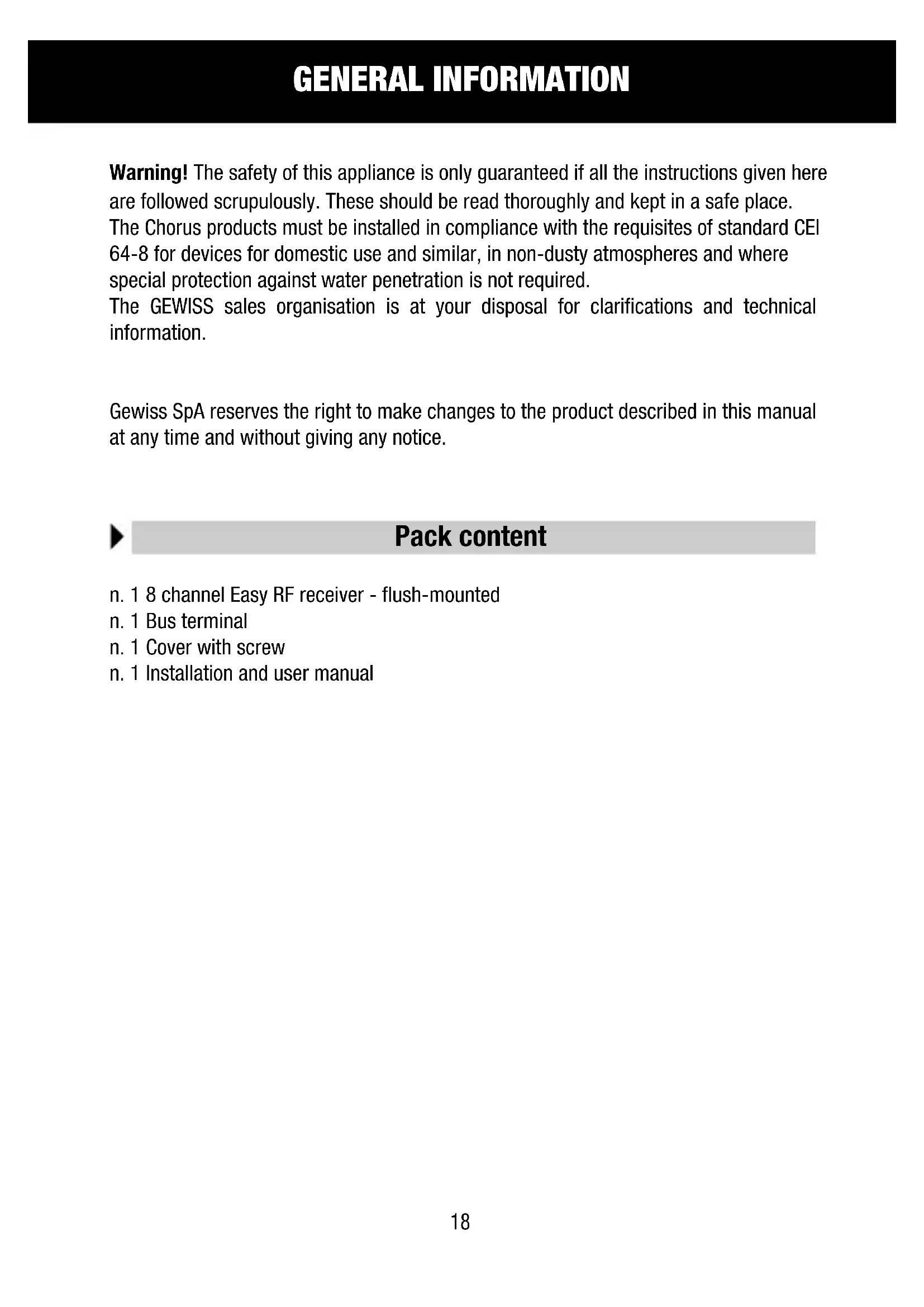
Pack content
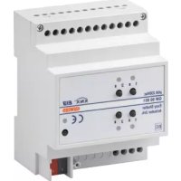
n. 18 channel Easy RF receiver - flush-mounted
n. 1 Bus terminal
n. 1 Cover with screw
n. 1 Installation and user manual
Summary
The Easy 8 channel RF Receiver - flush-mounted, allows the Chorus system RF command and control devices to communicate with a KNX/EIB system, which hence allows the Home Automation EIB Easy system to be extended using RF command devices.
The receiver is identified by the Easy EIB system as an 8 channel input interface.
Up to 4 different RF command sources (transmitters) can be connected to each channel which manages a total of 32 channels of the RF remote control (GW 20 963), RF pushbutton panel (e.g. GW 14 803), IR with twilight switch RF movement detector (e.g. GW 14 811), 2 RF channel input modules (e.g. GW 14 813), etc.
The receiver is powered by the bus line.
The front button is used during the configuration phase to generate the localisation commands on the Easy channels identified by positions (1-8) on the rear rotating switch; in the same manner, using the switch in these positions, the wireless receiver is able to learn the combinations with the RF command devices.
The configuration status is indicated by the front LED.
The device is fitted inside a standard flush-mounted box, mounted on Chorus supports in the space of two modules.
Functions
Each RF receiver channel can be configured with the Easy base unit to perform one of the following functions:
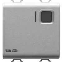
ON/OFF SWITCHING
This switches the KNX/EIB actuator output. Two buttons on the RF remote control, a button on the RF push-button panel, a RF timed-thermostat (e.g. GW 14 841) or a RF bidirectional (e.g. GW 14 851), a 2 RF channel input module or an IR with twilight switch RF movement detector can be used for this command.
DIMMING MANAGEMENT
This allows you to manage the lighting devices connected to a KNX/EIB dimmer. Each individual dimmer channel can be controlled using one button on the RF push-button panel, two buttons on the RF remote control or a 2 RF channel input module.
- long pressure (>0.5s) : regulation of the light intensity;
- short pressure (≤ 0.5s) : total On or Off option.
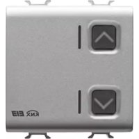
AWNING AND SHUTTER MANAGEMENT
This activates motorised awnings or shutters connected to a KNX/EIB actuator motor command.
Each individual awning or shutter function can be controlled using one button on the RF push-button panel, two buttons on the RF remote control or a 2 RF channel input module.
- long pressure (>0.5s) : shutter movement;
- short pressure ( ≤ 0.5 s): stop, if the shutter is moving; regulation of the laths if the shutter is at a standstill and only if the actuator is set to "blinds" mode.
ON COMMAND WITH TIMING
This allows you to activate an electrical load connected to a KNX/EIB actuator which is automatically deactivated when a certain time set on the actuator has elapsed. One button on the RF push-button panel or RF remote control, a 2 RF channel input module or an IR with twilight switch RF movement detector.
SCENE MANAGEMENT
This allows you to manage a scene. The scene can be controlled using a button on the RF push-button panel or RF remote control (two scenes per channel) or a 2 RF channel input module.
- short pressure (≤ 3s) : activation of the scene;
- long pressure ( >3 s): memorising of new scene values.
SEND PRIORITY CONTROLS
Using the buttons on the RF push-button panel or RF remote control or a 2 RF channel input module, it is possible to override the status (fixed ON or OFF, regulated at choice) of a KNX/EIB device.
This function can be used, for instance to keep lights ON, ignoring other switch-off commands.
At the end of the override, if no other commands are received the commanded devices return to their previous status before the override was activated. Otherwise the status remains that of the last command received during override.

Commands sent to the KNX/EIB
According to the type of RF device used, the action performed by the same and the functions set on the receiver KNX/EIB channel, the receiver will send the KNX/EIB bus a precise command, as seen in the charts below.
GENERAL DESCRIPTION
| IR with twilight switch RF movement detector | |||
| RF device Function configured on the receiver EIB channel | |||
| sensor action switching timer mode | |||
| IR activation - ON | |||
| IR + twilight switch activation - ON | |||
| Twilight switch activation ON ON | |||
| deactivation OFF OFF | |||
| RF timed-thermostat or RF bi-directional timed-thermostat | |
| RF device action | Function configured on the receiver EIB channel |
| switching | |
| System ON ON | |
| System OFF OFF | |
| RF command push-button panel or RF remote control | ||||
| RF device Function | configured on the receiver EIB channel | |||
| channel action switching | dimming blinds | |||
| top or right | short pressure | ON | ON | Stop movement/ regulation of laths |
| long pressure | - | Increases light intensity | Moves shutter UP | |
| bottom or left | short pressure | OFF OFF | Stop movement/ regulation of laths | |
| long pressure | - | decreases light intensity | Moves shutter down | |
| channel action timer mode scene priority control | ||||
| Top or right | short pressure | ON | activates scene A | activates override |
| long pressure | - | learns scene A | - | |
| bottom or left | short pressure | OFF | activates scene B | deactivates override |
| long pressure | - | learns scene B | - | |
GENERAL DESCRIPTION
| 2 RF channel input module | ||||
| RF device Function configured on the receiver EIB channel | ||||
| channel action switching dimming blinds | ||||
| 1 (combined input mode) | short pressure ON ON | stop movement/ regulation of laths | ||
| long pressure - | increases light intensity | moves shutter UP | ||
| 2 (combined input mode) | short pressure OFF OFF | stop movement/ regulation of laths | ||
| long pressure - | decreases light intensity | moves shutter down | ||
| 1 and 2 (status mode)* | contact closes ON - moves shutter up | |||
| contact opens OFF - Moves shutter down | ||||
| 1 and 2 (toggle mode) | contact closes toggle - | - | ||
| contact opens - | - | - | ||
| 1 and 2 (always ON mode) | contact closes ON - moves shutter up | |||
| contact opens - | - | - | ||
| 1 and 2 (always OFF mode) | contact closes OFF - moves shutter down | |||
| contact opens - | - | - | ||
continues on the following page
GENERAL DESCRIPTION
| 2 RF channel input module | ||||
| RF device Function | configured on the receiver EIB channel | |||
| channel | action timer mode | scene priority control | ||
| 1 (combined input mode) | short pressure ON | activates scene A | activates override | |
| long pressure - | learns scene A | - | ||
| 2 (combined input mode) | short pressure OFF | activates scene B | deactivates override | |
| long pressure - | learns scene B | - | ||
| 1 and 2 (status mode) * | contact closes - | - activates override | ||
| contact opens - | - deactivates override | |||
| 1 and 2 (toggle) | contact closes | - - | ||
| contact opens | - - | |||
| 1 and 2 (always ON mode) | contact closes ON - activates override | |||
| contact opens | - - | |||
| 1 and 2 (always OFF mode) | contact closes OFF - deactivates override | |||
| contact opens | - - | |||
*The RF message and consequently the KNX/EIB telegram are repeated every 10 minutes
INSTALLATION

WARNING: the installation of the device must be exclusively done by qualified personnel, following the regulations in force and the guidelines for KNX/EIB installations.
Warnings for KNX/EIB installations
- The length of the bus line between the 8 channel Easy RF Receiver and the power supply unit must not exceed 350 metres.
- The length of the bus line between the 8 channel Easy RF Receiver and the most distant KNX/EIB device must not exceed 700 metres.
- If possible do not create ring circuits so as to prevent undesirable signals and overloads.
- Keep a distance of at least 4mm between the individually insulated cables of the bus line and those of the electric line (figure C).
- Do not damage the electrical continuity conductor of the shielding (figure D).
WARNING: the unused bus signal cables and the electrical continuity conductor must never touch elements under power or the earth conductor!
Good wireless connection recommendations
- Install the receiver in a "central" position in relation to the various RF devices it must receive commands from.
- Install the receiver as far as possible from all sources of electromagnetic disturbances, such as electrical motors, electricity meters, electrical appliances.
- Do not install the receiver near or behind metal surfaces.
- Do not install the receiver inside metal electrical panels or junction boxes mounted inside reinforced concrete walls.
Electrical connections
Figure B shows the electrical connections diagram.
- Connect the bus cable's red wire to the terminal's red connector (+) and the black wire to the black connector (-). Up to 4 bus lines (wires of the same colour in the same connector) can be connected to the terminal (figure E).
- Insulate the screen, the electrical continuity conductor and the remaining white and yellow wires of the bus cable (should a bus cable with 4 conductors be used), which are not needed (figure D).
- Insert the bus connector into the special feet of the device. The fastener guides determine the direction it should be inserted. Insulate the bus terminal using the relative cover, which must be screwed onto the device. The cover guarantees that the power cables and the bus cables are separated by at least 4mm (figure F).
Initialization with the Easy base unit
- Power up the device through the bus.
-
Have the system acquire the device with one of the following procedures:
-
Automatic acquisition (the device still has the factory settings):
- select the "Application New function" or "Application Edit function" menu in the Easy base unit: the device will be recognized automatically.
- Manual acquisition (the factory settings have been modified):
- select the "Application Search device" menu in the Easy base unit;
- briefly press (< 2 seconds) the programming key. The programming LED will light up during the acquisition process (figure A).
The device acquired by the Easy base unit will be listed, with the number assigned, in the channels of the "Application New function" or "Application Edit function" menus.
RF channel learning process
To memorise the combinations between the RF transmitter devices and the receiver, please proceed as follows:
- Turn the rotating switch on the receiver to position 1: the front LED will come ON (red) to indicate that the receiver is ready to receive a learning RF message to be memorised.
INSTALLATION
- Follow the instructions for the device that must be combined to generate the required command message.
The LED will go OFF to indicated that the RF message has been learnt.
- After 5 seconds the LED will come back ON and it is possible to memorise another RF message, repeating the procedure 2 above. If the LED flashes (red), this means that the memory is full (4 transmitters memorised on each channel) and it is therefore necessary to use another channel.
- If necessary, turn the rotating switch to the next position (2, 3... 8) and repeat procedure 2 to memorise the other transmitters.
WARNING: Do not turn the rotating switch to position 9.
- After memorising all the required transmitters, turn the rotating switch to position 0 for standard functions In this position the receiver LED flashes green briefly each time it receives a message from any of the learnt RF devices.
Cancelling learnt RF channels
To cancel the combinations memorised on the various RF channels, turn the rotating switch to position 9: the front LED will flash for 10 seconds (yellow) and then remain ON (yellow) to indicate that all the channel combinations have been cancelled.
To interrupt the cancellation procedure, turn the selector switch to another position before the LED stops flashing.

WARNING: It is not possible to perform selective cancellations: the cancellation operation requires new learning of all the required RF transmitters.
Completing installation
Insert the device into a Chorus support, making sure the Easy EIB channel localisation button is on the left.
Complete the installation with other Chorus devices or covers and fix it to the relative container (flush-mounted box, wall-mounted box etc).
Apply the finish plate.
PROGRAMMING WITH THE EASY BASE UNIT
Programming the channels through the Easy base unit (code GW 90 831).
The channel to be used can be selected, at choice:
- by activating the RF command (when the combination of the RF channels to the KNX/EIB, as described in the RF Channel Learning process paragraph, has been completed): the corresponding channel will be highlighted in the channel list in the "Application New function" or "Application Edit function" menu and the front LED on the receiver will flash green;
- by turning the rotating switch to the channel number to be programmed and pressing the front button on the receiver: the corresponding channel will be highlighted in the channel list in the "Application New function" or "Application Edit function" menu and the front LED on the receiver will flash green;
- directly from the list of channels of the "Application New function" or "Application Edit function" menus.
The functions can be created after the device has been selected.
| Names of the functions on the Easy base unit | |
| switching ON-OFF command | |
| timer mode | command ON with timer (the time is set on the actuator) |
| scene scene management | command |
| priority control send priority controls | |
| dimming dimming management | command |
| blinds blinds management | command |
The chart below lists the base unit functions to be used according to the selected RF device.
| Function New: IR with twilight switch RF movement detector | RF command push-button panel or RF remote control | RF timed-thermostat or RF bi-directional timed-thermostat | 2 RF channel input module |
| switching | ■ | ■■■ | |
| timer mode | ■■■ | ||
| scene | ■ | ||
| priority control | ■ | ||
| dimming | ■ | ||
| blinds | ■ |
Refer to the Easy base unit documentation for further information on the programming procedures.
Configuration parameters (Easy)
After creating the desired function, it is possible to set the device function parameters from the "Application Parameters" menu.
The parameters available, in relation to the function created, are listed in the following table.
The underlined value is the default value.
| Function: scene | |
| Parameter: scene number A - scene number B | |
| 1 activation of scene 1 (prolonged closure: memorising of the scene) | |
| 2 activation of scene 2 (prolonged closure: memorising of the scene) | |
| 3 activation of scene 3 (prolonged closure: memorising of the scene) | |
| 4 activation of scene 4 (prolonged closure: memorising of the scene) | |
| 5 activation of scene 5 (prolonged closure: memorising of the scene) | |
| 6 activation of scene 6 (prolonged closure: memorising of the scene) | |
| 7 activation of scene 7 (prolonged closure: memorising of the scene) | |
| 8 activation of scene 8 (prolonged closure: memorising of the scene) |
| Function: priority control |
| Parameter: priority control |
| Off/Up off and up priorities On/Down on and down priorities |
| Function: dimming |
| Parameter: pushbutton function |
| up increases light intensity, on down decreases light intensity, OFF |
| Function: blinds |
| Parameter: pushbutton function |
| up_raising of blinds, regulation of laths DOWN lowering of blinds, regulation of laths |
IN SERVICE
Behaviour on the failure and reinstatement of the bus power supply
When the bus power supply fails, the device performs no actions. The device is in full operating mode upon reinstatement of the bus power supply.
Maintenance
This device requires no maintenance. Use a dry cloth for possible cleaning.
TECHNICAL DATA
| Communication | Bus KNX/EIB |
| RF communication frequency | 868 MHz |
| Power Supply | By KNX/EIB, 29 V dc SELV bus |
| Bus cable | KNX/EIB TP1 |
| Bus current consumption | 15 mA max |
| Control elements | 1 mini programming key |
| 1 front KNX/EIB configuration button | |
| 1 10 position rotating switch: | |
| 0 →standard function mode | |
| 1 ...8 → channel learning and localisation | |
| 9 →cancellation | |
| Display elements | 1 red programming LED |
| 1 multi-function LED (red-green-yellow) | |
| for learning and localisation processes | |
| Ambit of use | Indoors, dry places |
| Operating temperature | -5 +45 °C |
| Storage temperature | -25 +70 °C |
| Relative humidity | Max 93% (no condensation) |
| Bus connection | 2-pin Ø 1 mm plug connector |
| Protection rating | IP20 |
| Dimensions | 2 Chorus modules |
| Reference standards | Low Voltage Directive 2006/95/EC |
| Electromagnetic Compatibility Directive 89/336/EEC | |
| R&TTE 99/05/CEE, EN50428, EN50090 | |
| Certification | KNX/EIB |
SOMMAIRE
page AVERTISSEMENTS GENERAUX 32
DESCRIPTION GENERALE 33
INSTALLATION 38
PROGRAMMATION AVEC UNITE DE BASE EASY 41
EN SERVICE 43
DONNEES TECHNIQUES 44