GW14797 - Smart Home Gewiss - Free user manual and instructions
Find the device manual for free GW14797 Gewiss in PDF.

| Product Type | 1-channel KNX motor control actuator 6 A |
| Brand | Gewiss |
| Model | GW14797 |
| Category | Smart Home |
| Power Supply | KNX bus, 29 V DC SELV |
| Current consumption (bus) | 8 mA max |
| Outputs | 2 NO relays, 8 A (cosφ=1), 250 V AC; motors 6 A (EN60669-2-1) |
| Dimensions | 2 Chorus modules (36 mm width) |
| Weight | Approximately 100 g |
| Operating temperature | -5 to +45 °C |
| Storage temperature | -25 to +70 °C |
| Relative humidity | Max. 93 % (non-condensing) |
| Protection rating | IP20 |
| Bus connection | 2-pin plug terminal Ø 1 mm |
| Electrical connections | Screw terminals, max. cross-section 4 mm² |
| Control elements | 1 physical address programming button, 2 local control buttons |
| Display elements | 1 red LED (programming), 2 green LEDs (output status), 2 amber LEDs (night localization) |
| Main functions | Up/down/stop control, slat adjustment, relative position, scenarios (8), priorities, blocking, alarms (3 sensors), status information |
| Configuration | ETS (KNX) software |
| Installation | By qualified personnel, on Chorus support, comply with KNX standards |
| Maintenance | No specific maintenance; keep clean and dry |
| Safety | Comply with low voltage and EMC directives; install with power off |
| Spare parts and repairability | Not applicable (sealed device) |
| Standards | EN50428, EN50090-2-2, KNX certifications |
Frequently Asked Questions - GW14797 Gewiss
User questions about GW14797 Gewiss
0 question about this device. Answer the ones you know or ask your own.
Ask a new question about this device
Download the instructions for your Smart Home in PDF format for free! Find your manual GW14797 - Gewiss and take your electronic device back in hand. On this page are published all the documents necessary for the use of your device. GW14797 by Gewiss.
USER MANUAL GW14797 Gewiss
PROGRAMMING WITH ETS SOFTWARE 16
TECHNICAL DATA 17
GENERAL DESCRIPTION
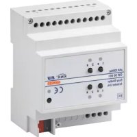
The 1 channel 6A KNX motor command actuator controls the movement of motorised shutters, curtains and blinds. 2 output relays, one for UP and one for DOWN movements, are interlocked to avoid damage to the connected motor.
The movement commands can be accessed through Building Automation control or sensor devices using the KNX bus, or they can be generated locally using the front buttons.
The actuator is powered by the bus line and is fitted with 4 front LEDs: 2 green LEDs to indicate that the shutters are moving (up/down) and 2 amber LEDs for night localisation.
Functions
The actuator is configured by the ETS software to achieve one of the functions listed below.
Control functions
- up/down/stop movement control
- lath regulation
- movement command to relative position (0%-100%)
- automatic regulation of the lath position
Scenes:
- memorising and activation of 8 scenes (value 0-63)
- enabling/disabling memorising of scenes via bus
Priority controls:
- setting of the position at the end of the forced command
Block command:
- Setting of the position at the end of the block command
Alarms:
- management of alarm positions (up to 3 sensors) and periodic monitoring of input objects
Status information:
- sending to bus with settable parameters
- information on last performed movement
- position indication (0%-100%)
Other functions:
- output behaviour setting during bus blackout/reinstatement
GENERAL DESCRIPTION

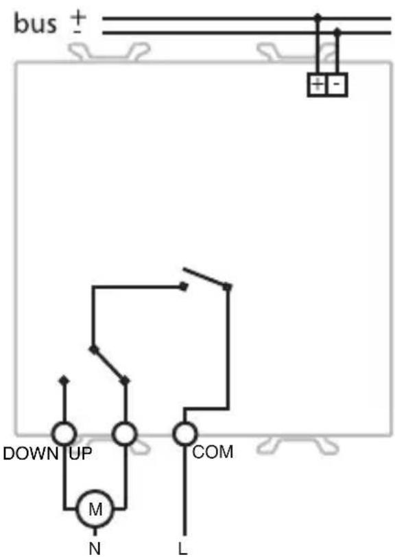
Connection diagram
INSTALLATION

WARNING: only qualified personnel are permitted to install this device, according to the regulations in force and guide lines provided for KNX installation in the Technical Manual.
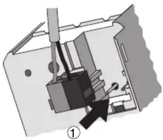
Electrical connections
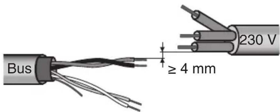
Minimum bus distance - electrical power line
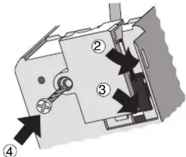
Slot in terminal fixing
INSTALLATION
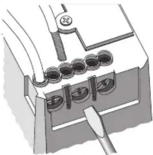
Loads connection
Completing installation
Insert the devices into a Chorus support, making sure the two local command buttons are on the left.
Complete the installation with other Chorus devices or hole covers and fix it to the relative container (flush-mounted box, wall-mounted box etc).
Apply the finish plate.
PROGRAMMING WITH ETS SOFTWARE
This device must be configured using the ETS software.
Detailed information on the configuration parameters and their values can be found in the
Technical Manual.
Communication KNX Bus
Power Supply By KNX Bus, 29 V dc SELV
Bus cable KNX TP1
Bus current consumption 8 mA max
Control elements 1 mini physical address programming key,
2 relay local command buttons
Display elements 1 red physical address programming LED,
2 green output status indicator LEDs,
2 amber LED for night localisation
Actuator elements 1 single-pole relay with phase branch circuit
1 single-pole relay with exchange contact and
phase branch circuit
Output contact 2 NO 8 A (cosφ=1) - 250 V ac
Max current per load type
Motors and reduction units: 6A according to EN60669-2-1
Resistive load: 8 A
Ambit of use Indoors, dry places
Operating temperature -5 ÷ +45 °C
Storage temperature -25 ÷ +70 °C
Relative humidity Max 93% (no condensation)
Bus connection Slot in terminal, 2 pin 1 mm
Electrical connections
Screw terminals, Max cable width: 4mm^2
Protection rating
IP20
Dimensions
2 Chorus modules
Reference standards Low Voltage Standard 2006/95/EC
Electromagnetic Compatibility Standard 2004/108/EC
EN50428, EN50090-2-2
Certifications
KNX
SOMMAIRE
page
DESCRIPTION GENERALE 20
INSTALLATION 22
PROGRAMMATION AVEC LOGICIEL ETS 24
PROGRAMMATION AVEC LOGICIEL ETS
Communication Bus KNX
According to article 9 paragraph 2 of the European Directive 2004/108/EC and to article R2 paragraph 6 of the Decision 768/2008/EC, the responsible for placing the apparatus on the Community market is:
GEWISS S.p.A Via A. Volta, 1-24069 Cenate Sotto (BG) Italy Tel: +39 035 946 111 Fax: +39 035 945 270 E-mail: qualitymarks@gewiss.com


+39035946111
8.30-12.30/14.00-18.00
lunedi ÷ venerdi - monday ÷ friday

+39 035 946 260

sat@gewiss.com
www.gewiss.com