PEM10D2 - Detector VELLEMAN - Free user manual and instructions
Find the device manual for free PEM10D2 VELLEMAN in PDF.
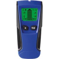
| Product type | Laser beam detector (infrared barrier) |
| Brand | Velleman |
| Model | PEM10D2 |
| Dimensions (emitter) | 122 (H) x 60 (W) x 62 (D) mm |
| Dimensions (reflector) | 80 x 7 mm |
| Weight | Approximately 200 g |
| Power supply | 12-250 V AC or DC (no polarity) |
| Range | ≤ 10 m |
| Beam angle | 1.5° |
| Emitter | Infrared LED, wavelength 750 nm |
| Response time | 10 ms |
| Relay response time | 100 ms |
| Output contacts | NC (normally closed) and NO (normally open), max load 0.5 A / 120 V or 1 A / 30 V DC |
| Tamper protection | Tamper contact (TP1/TP2) open when housing is closed |
| Protection rating | IP44 |
| Housing material | ABS, PMMA cover |
| Operating temperature | -25 °C to +60 °C |
| Storage temperature | -35 °C to +80 °C |
| Maintenance and cleaning | Regularly clean the cover and reflector with a soft, lint-free cloth slightly damp |
| Safety | Use indoors, protect from moisture and splashes. Installation and repair by qualified personnel only. |
| Spare parts and repairability | No user-serviceable parts. Contact the dealer for any spare parts. |
| General information | 24-month warranty for consumer products (EU). Follow environmental directives for disposal. |
Frequently Asked Questions - PEM10D2 VELLEMAN
User questions about PEM10D2 VELLEMAN
0 question about this device. Answer the ones you know or ask your own.
Ask a new question about this device
Download the instructions for your Detector in PDF format for free! Find your manual PEM10D2 - VELLEMAN and take your electronic device back in hand. On this page are published all the documents necessary for the use of your device. PEM10D2 by VELLEMAN.
USER MANUAL PEM10D2 VELLEMAN
To all residents of the European Union Important environmental information about this product
This symbol on the device or the package indicates that disposal of the device after its lifecycle could harm the environment. Do not dispose of the unit (or batteries) as unsorted municipal waste; it should be taken to a specialized company for recycling. This device should be returned to your distributor or to a local recycling service. Respect the local environmental rules.
If in doubt, contact your local waste disposal authorities.
Thank you for choosing Velleman! Please read the manual thoroughly before bringing this device into service. If the device was damaged in transit, do not install or use it and contact your dealer.
Notes
- It is recommended to use this device indoors. Rain drops and condensation may influence its operation.
2. Safety Instructions
Keep this device away from children and unauthorized users.
Indoor use only. Keep this device away from rain, moisture, splashing and dripping liquids. Never put objects filled with liquids on top of or close to the device.
Be very careful during the installation: touching live wires can cause life-threatening electroshocks.
There are no user-serviceable parts inside the device.
Refer to an authorized dealer for service and/or spare parts.
Have the device installed/ repaired by a qualified person.
Do not use the device when damage to housing or cables is noticed. Do not attempt to service the device yourself but contact an authorised dealer.
3. General Guidelines
Refer to the Velleman® Service and Quality Warranty on the last pages of this manual.
- Protect this device from shocks and abuse. Avoid brute force when operating the device.
- Familiarise yourself with the functions of the device before actually using it.
- All modifications of the device are forbidden for safety reasons. Damage caused by user modifications to the device is not covered by the warranty.
- Only use the device for its intended purpose. Using the device in an unauthorised way will void the warranty.
- Damage caused by disregard of certain guidelines in this manual is not covered by the warranty and the dealer will not accept responsibility for any ensuing defects or problems.
- The user is responsible for the proper connection and functioning of the device and the follow up of possible alarm outputs. Velleman Group nv cannot be held responsible for any loss of goods or other damage caused by neglecting alarm conditions or due to misuse or malfunctioning of the device.
- Keep this manual for future reference.
4. Overview
Refer to the illustrations on page 2 of this manual.
| A | hood | G | terminals |
| B | mounting bracket | H | cover |
| C | transmitter/receiver lens | I | gland |
| D | alignment LED | J | mounting bolt |
| E | tamper switch | K | wall cable hole |
| F | vertical alignment bolt | L | screw (4x) |
PEM10D2
Terminals (image page 3)
| 1 | input voltage | input voltage 12 ~ 250 V AC or DC (no polarity) |
| 2 | input voltage | |
| 3 | NC | output contacts normally closed between 3 and 5 Normally open between 4 and 5 |
| 4 | NO | |
| 5 | COM | |
| 6 | TP1 | tamper contact: open when tamper switch is pressed (cover is closed) |
| 7 | TP2 |
5. Installation
- Determine a location for the system. Avoid direct sunlight on the transmitter/receiver lens [C] and note that the maximum distance to the reflector is 10m . Make sure to point towards a flat surface to which the reflector can easily be mounted. Also keep in mind that when mounting the system too low, an alarm might accidentally be triggered by small animals e.g. pets.
- Remove the mounting bracket [B] from the housing by releasing the two mounting bolts [J].
- Use the mounting bracket [B] as a template to determine the position of the mounting holes and mount the bracket with 2 screws.
- When the cable needs to go through a wall cut away the wall cable hole [K]; hang the housing over the mounting bracket and mark the location of the cable hole. Remove the housing and drill the hole and provide the necessary cabling. Mount the included rubber seal in the wall cable hole.
- When the cable runs on top of the wall cut away the hole at the bottom of the housing and mount the cable gland [I] in the opening (do not tighten the nut that covers the conical part). Provide the necessary cabling.
- Guide the control cables through the back or cable gland of the housing. Tighten the cable gland.
- Make the proper connections to the terminals (see §4).
Note:
To facilitate the connections of the wiring, lift the sensor assembly from the housing.
PEM10D2
To do this, release the 4 screws [L] (2 large ones on top, 2 small ones near the bottom).
o After making all connections gently reseat the sensor assembly and put the 4 screws back.
- Attach the housing to the mounting bracket and secure it with the two mounting bolts [J].
- Apply power to the system. The alignment LED [D] will turn red since no reflector is detected.
- Place the reflector in line with the transmitter/receiver lens [C] until the alignment LED [D] turns green. Mark the position of the reflector and mount it in that location.
- Note: the lens can be aligned horizontally ( ± 25^ ) by rotating the entire lens head (do not force) or vertically using the vertical alignment bolt [F].
- Close the cover [H] with the 4 screws and slide the hood [A] in place.
- Note: by closing the cover, the tamper switch [E] is pressed and the tamper contact [6]/[7] is closed.
6. Operation
- When the beam between transmitter and receiver is broken, the alignment LED [D] turns red and an alarm is triggered on the output contacts until the beam is restored:
[3] - [5]: open contact
[4] - [5]: closed contact
-
When the alignment LED [D] flashes red and green alternately an alignment problem occurs. Open the cover and slowly adjust the horizontal and/or vertical angle [F] of the lens [C].
-
In case somebody opens the cover, the tamper switch [E] is released and the tamper contact is closed:
[6] - [7]: closed contact
7. Cleaning and Maintenance
- Make sure the cover and reflector are clean at all times.
- Remove dirt with a soft lightly moist lint-free cloth.
8. Technical Specifications
cover .PMMA (Polymethyl Methacrylate)
housing ABS (Acrylonitrile Butadiene Styrene)
IP-rating IP44
input voltage 12-250 V AC or DC
transmitter . IR LED, wavelength 750 nm
range. ≤ 10m
beam spreading angle. 1.5°
contact capacity .0.5 A/120 V\~ (1 A/30 VDC)
response time 10 ms
delay time of relay. 100 ms
operating temperature -25 °C to +60 °C
storage temperature. -35 °C to +80 °C
dimensions
transmitter. 122 (H) x 60 (W) x 62 (T)
reflector 80 x 7 mm
weight ± 200g
Use this device with original accessories only. Velleman Group nv cannot be held responsible in the event of damage or injury resulting from (incorrect) use of this device. For more info concerning this product and the latest version of this manual, please visit our website www.VELLEMAN.eu. The information in this manual is subject to change without prior notice.
© COPYRIGHT NOTICE
The copyright to this manual is owned by Velleman Group nv.
All worldwide rights reserved. No part of this manual may be copied, reproduced, translated or reduced to any electronic medium or otherwise without the prior written consent of the copyright holder.
HANDLEIDING
1. Inleiding
Terminals (afb. p. 3)
behuizing ABS (acrylonitril-butadieen-styreen)
IP-norm IP44
ingangsspanning 12-250 V AC or DC
zender . infraroodled, golfhte 750 nm
bereik 10 m
tampa .PMMA (Polymethyl Methacrylate)
Velleman® Service and Quality Warranty
Since its foundation in 1972, Velleman® acquired extensive experience in the electronics world and currently distributes its products in over 85 countries.
All our products fulfil strict quality requirements and legal stipulations in the EU. In order to ensure the quality, our products regularly go through an extra quality check, both by an internal quality department and by specialized external organisations. If, all precautionary measures notwithstanding, problems should occur, please make appeal to our warranty (see guarantee conditions).
General Warranty Conditions Concerning Consumer Products (for EU):
- All consumer products are subject to a 24-month warranty on production flaws and defective material as from the original date of purchase.
- Velleman® can decide to replace an article with an equivalent article, or to refund the retail value totally or partially when the complaint is valid and a free repair or replacement of the article is impossible, or if the expenses are out of proportion.
You will be delivered a replacing article or a refund at the value of 100% of the purchase price in case of a flaw occurred in the first year after the date of purchase and delivery, or a replacing article at 50% of the purchase price or a refund at the value of 50% of the retail value in case of a flaw occurred in the second year after the date of purchase and delivery.
- Not covered by warranty:
- all direct or indirect damage caused after delivery to the article (e.g. by oxidation, shocks, falls, dust, dirt, humidity...), and by the article, as well as its contents (e.g. data loss), compensation for loss of profits;
- consumable goods, parts or accessories that are subject to an aging process during normal use, such as batteries (rechargeable, non-rechargeable, built-in or replaceable), lamps, rubber parts, drive belts... (unlimited list);
-
flaws resulting from fire, water damage, lightning, accident, natural disaster, etc....;
-
flaws caused deliberately, negligently or resulting from improper handling, negligent maintenance, abusive use or use contrary to the manufacturer's instructions;
- damage caused by a commercial, professional or collective use of the article (the warranty validity will be reduced to six (6) months when the article is used professionally);
- damage resulting from an inappropriate packing and shipping of the article;
- all damage caused by modification, repair or alteration performed by a third party without written permission by Velleman®.
- Articles to be repaired must be delivered to your Velleman® dealer, solidly packed (preferably in the original packaging), and be completed with the original receipt of purchase and a clear flaw description.
- Hint: In order to save on cost and time, please reread the manual and check if the flaw is caused by obvious causes prior to presenting the article for repair. Note that returning a non-defective article can also involve handling costs.
- Repairs occurring after warranty expiration are subject to shipping costs.
- The above conditions are without prejudice to all commercial warranties.
The above enumeration is subject to modification according to the article (see article's manual).