MegaView 50 - Audio/video extension MARMITEK - Free user manual and instructions
Find the device manual for free MegaView 50 MARMITEK in PDF.
Frequently Asked Questions - MegaView 50 MARMITEK
User questions about MegaView 50 MARMITEK
0 question about this device. Answer the ones you know or ask your own.
Ask a new question about this device
Download the instructions for your Audio/video extension in PDF format for free! Find your manual MegaView 50 - MARMITEK and take your electronic device back in hand. On this page are published all the documents necessary for the use of your device. MegaView 50 by MARMITEK.
USER MANUAL MegaView 50 MARMITEK
natural_image
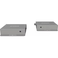
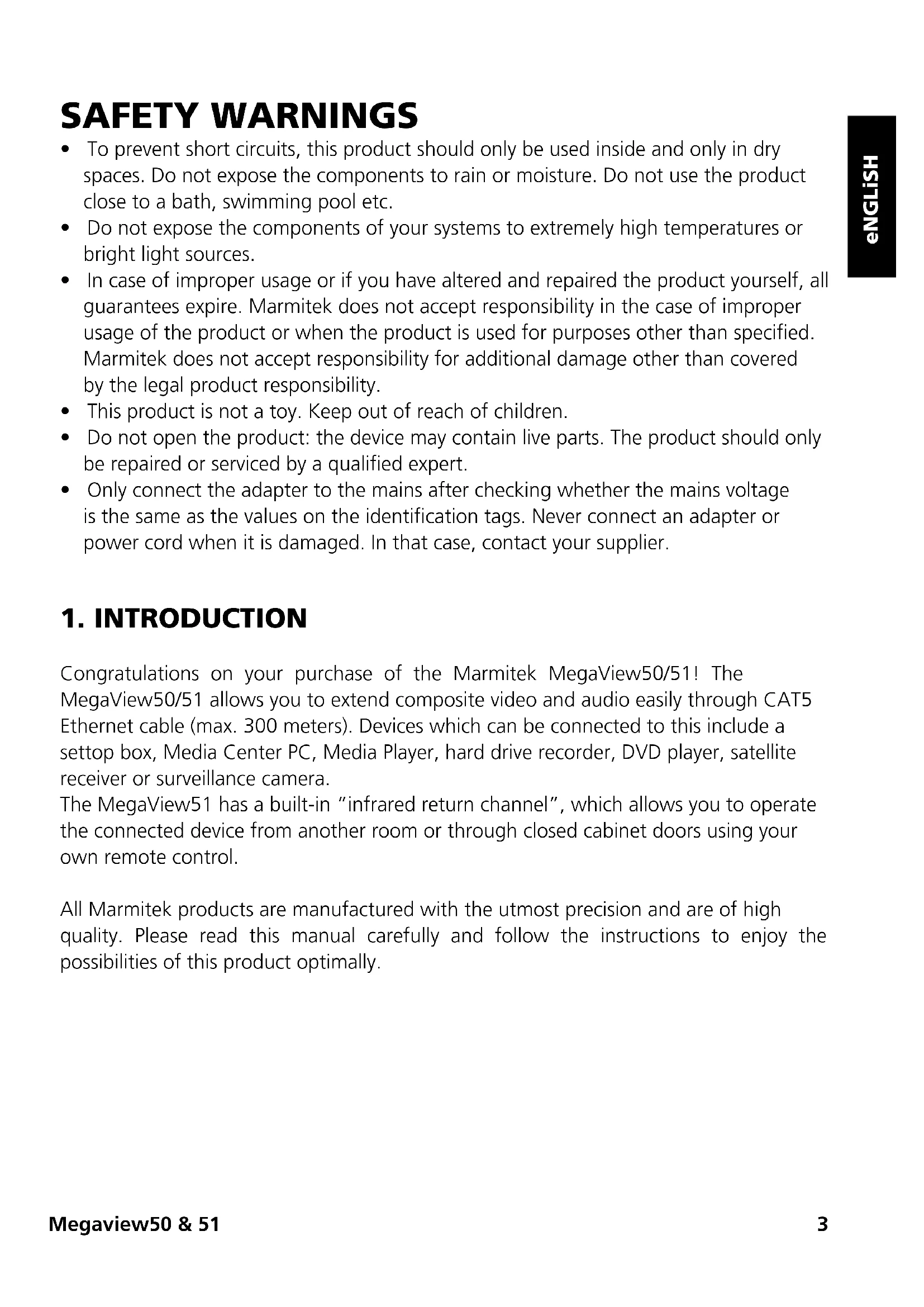
Black electronic device with three ports and a label (no visible text or symbols on the device body)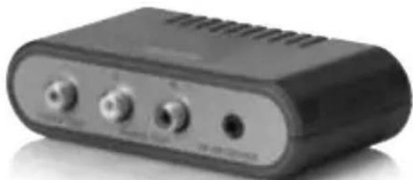
natural_image
Black electronic device with three ports and ventilation slots (no visible text or symbols)USeR MaNUaL 3
geBRaUCHSaNLeiTUNg 9
gUiDe UTiLiSaTeUR 15
MODO De eMPLeO 21
MaNUaLe D'iSTRUZiONe 27
geBRUiKSaaNwiJZiNg 33
SAFETY WARNINGS
- To prevent short circuits, this product should only be used inside and only in dry spaces. Do not expose the components to rain or moisture. Do not use the product close to a bath, swimming pool etc.
- Do not expose the components of your systems to extremely high temperatures or bright light sources.
- In case of improper usage or if you have altered and repaired the product yourself, all guarantees expire. Marmitek does not accept responsibility in the case of improper usage of the product or when the product is used for purposes other than specified. Marmitek does not accept responsibility for additional damage other than covered by the legal product responsibility.
- This product is not a toy. Keep out of reach of children.
- Do not open the product: the device may contain live parts. The product should only be repaired or serviced by a qualified expert.
- Only connect the adapter to the mains after checking whether the mains voltage is the same as the values on the identification tags. Never connect an adapter or power cord when it is damaged. In that case, contact your supplier.
1. INTRODUCTION
Congratulations on your purchase of the Marmitek MegaView50/51! The MegaView50/51 allows you to extend composite video and audio easily through CAT5 Ethernet cable (max. 300 meters). Devices which can be connected to this include a setup box, Media Center PC, Media Player, hard drive recorder, DVD player, satellite receiver or surveillance camera.
The MegaView51 has a built-in “infrared return channel”, which allows you to operate the connected device from another room or through closed cabinet doors using your own remote control.
All Marmitek products are manufactured with the utmost precision and are of high quality. Please read this manual carefully and follow the instructions to enjoy the possibilities of this product optimally.
2. CONTENT OF THE PACKING
MegaView50 MegaView51
1x transmitter (Audio/Video Transmitter) 1x transmitter (Audio/Video Transmitter)
1x receiver (Audio/Video Receiver) 1x receiver (Audio/Video Receiver)
1x User manual 1x Infrared receiver
1x Infrared extender cable with 2 IR LEDs
1x Power adapter
1x User manual
3. CAT5E CABLE REQUIREMENTS
- UTP-, FTP- or STP-cable
- 24AWG or lower
- Solid twisted pair
• 100 ohm at 1MHz
• RJ-45 jack according to EIA/TIA T568B standard
Instead of CAT5 cable, CAT6 cable may also be applied (this offers better quality).
4. INSTALLATION
text_image
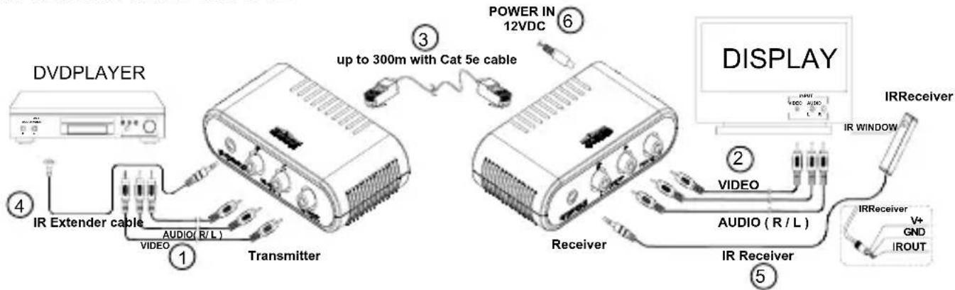
DVDPLAYER ① ② ③ ④ ⑤ ⑥ POWER IN 12VDC up to 300m with Cat 5e cable TRANSMITTER IR Extender cable AUDIO (R/L) VIDEO TRANSMITTER DISPLAY IR Receiver IR WINDOW VIDEO AUDIO (R/L) IR Receiver V+ GND IROUTIn order to check the correct operation of the system, it is recommended to check the planned set-up first. For this purpose, please connect everything as indicated below but do not yet stick the components or fasten the screws.
- Switch off all A/V devices before you start connecting.
-
Connect the A/V device (for instance the setup box or Media Center PC) to the Audio and Video IN of the MegaView50/51 transmitter (Audio/Video Transmitter) [1] using a cinch cable (not included).
-
Connect the MegaView50/51 receiver (Audio/Video Receiver) to your display device [2] (for instance TV or projector) using a cinch cable (not included).
Please make sure that the colours of the plugs correspond to the input sockets. That means red to red, white to white and yellow to yellow.
- Use a CAT5 Ethernet cable (not included) to connect the MegaView50/51 transmitter and receiver to each other [3].
INSTALLATION IR (INFRARED) RETURN (MEGAVIEW51 only)
- Position the MegaView51 transmitter at an accessible location behind or next to your A/V devices and close to a wall socket. Please take into account the cable length of the IR LEDs and make sure that the connections remain accessible.
-
Plug the required IR Extender cable (with the 2 IR LEDs) [4] into the MegaView51 transmitter.
-
Self-adhesive foil has been supplied with the IR LEDs. This allows you to attach the IR LEDs to the IR sensor of your A/V device.
- Test the position and operation of the IR LEDs before sticking them definitively to the IR sensor of your A/V device.
- In case you want to operate another device besides your A/V device (of which you are transmitting the signal), you may use the second IR LED for this.
-
If you are only using one of the two IR LEDs, please leave the second IR LED unused. Never remove it from the extender cable!
-
Now connect the IR Receiver [5] to the MegaView51 receiver.
-
Position the supplied IR receiver in sight of your infrared remote control and as little as possible in the proximity of potential sources of interference such as direct sunlight, strip light, energy saving bulbs, etc. The infrared indicator LED in the IR receiver will light up or blink when it receives infrared communication. Use this indicator LED to position the IR receiver at the most interference-free location (indicator LED will not or hardly light up when it does not receive a signal).
- By using the supplied self-adhesive strip, placement is possible almost everywhere. Please experiment with the right positioning before definite attachment of the IR receiver.
-
Attention! The adhesive strip may cause discolouration on certain surfaces or leave behind traces of glue.
-
Connect the power adapter [6] to the "POWER" socket of the MegaView51 receiver and plug the adapter into a wall socket.
5. USAGE
- Switch on the connected A/V device (for instance setup box or Media Center PC).
- Switch on the display device (for instance TV or projector) and select the appropriate input. Usually you will do this by pressing the 0, A/V or EXT button of your remote control.
- You will receive images from the connected A/V device immediately.
- With the MegaView51 you may now also operate the connected device from this room using your own remote control, by pointing it at the IR receiver.
6. FREQUENTLY ASKED QUESTIONS
Bad (or no) image and sound
- Check if all cables are connected properly.
- Check if the A/V device is switched on.
- Use only CAT5 cable as specified in chapter 3 (CAT5e Cable Requirements).
- Check if the CAT5 cable provides a solid connection (no cable faults).
- Check if the RJ-45 has been connected according to the EIA/TIA T568B standard. Please refer to attachment page 39
- Please ensure that the maximum cable length is not exceeded.
- Check if the cinch cables on the A/V device, the screen and the MegaView50/51 have been connected to the correct colours.
• Install your system as far away from any RF sources (wireless devices).
Bad (or no) infrared return signal (MegaView 51)
- Both the built-in and the surface-mounted IR Receivers have a reception sensitivity of approx. 10 meters at a 90 degrees angle of aperture. Range is also dependent on the remote control used. The IR reception indicator LED in the IR receiver will light up on reception of an IR signal.
- Check if the power adapter has been connected to the MegaView51 transmitter
- Please ensure that the IR receiver and the IR extender cable have been connected properly and that they are fully plugged in.
- Please ensure that the LEDs of the IR extender cable are placed correctly to the infrared sensor of the A/V device, this has to be done very precisely. The exact position can be found easily by shining at it with a flashlight.
Do you have any questions that are not answered above?
Please check www.marmitek.com.
7. TECHNICAL DATA
MegaView50 MegaView51
Audio/Video
Bandwidth Video: 6 MHz 6 MHz
Bandwidth Audio: 20 Hz to 20 kHz 20 Hz to 20 kHz
Impedance Video: 75 ohm 75 ohm
Impedance Audio: 600 ohm 600 ohm
Max. Input Audio/Video: 1.1 Vp-p 1.1 Vp-p
Max. CAT5e cable length: 300 meters 300 meters
Audio/Video Transmitter
| A/V input: | RCA (1x Video, 2x Audio) | RCA (1x Video, 2x Audio) |
| Connection IR LED: | - | 1x 3.5mm jack plug |
| Dimensions: | 106 x 61 x 29 mm | 106 x 61 x 29 mm |
| Weight: | 79g | 84g |
Audio/Video Receiver
| A/V output: | RCA (1x Video, 2x Audio) | RCA (1x Video, 2x Audio) |
| IR receiver: | - | 1x 3.5mm jack plug |
| Power: - | 100-240VAC/50Hz, 12VC 500mA | |
| Dimensions: | 106 x 61 x 29 mm | 106 x 61 x 29 mm |
| Weight: | 79g | 84 g |
IR Receiver
| Frequency range: | - | 30-100 KHz |
| IR reception range: | - | ± 10 meters |
| Cable length: | - | 2 meters |
| IR receiver: | - | reception indicator LED: |
| IR angle of aperture: | - | 90° (+45°/-45° from centre) |
| Dimensions: | - | 51x10x8mm |
IR extender cable
| Connection: | - | 3.5 mm jack plug |
| IR LEDs: | - | 2x IR LED |
| Cable length: | - | 3 meters |
Specifications may be modified without prior notice.
8. OPTIONAL ACCESSORIES
Extra remote control
If you want to operate your device from various places in your home, or if you want to use just one single remote control for all your A/V devices, then make your choice from the complete range of Marmitek universal remote controls; EasyControl or EasyTouch. These replace almost every remote control you are using at the moment. More information about these so called universal remote controls can be found at www.marmitek.com.
Connecting multiple devices
You want to connect multiple A/V devices? With the Marmitek Connect series you can connect all your devices with just one cable, retaining quality. More information about this so called switchgear can be found at www.marmitek.com.
Environmental Information for Customers in the European Union
European Directive 2002/96/EC requires that the equipment bearing this symbol on the product and/or its packaging must not be disposed of with unsorted municipal waste. The symbol indicates that this product should be disposed of separately from regular household waste streams. It is your responsibility to dispose of this and other electric and electronic equipment via designated collection facilities appointed by the government or local authorities. Correct disposal and recycling will help prevent potential negative consequences to the environment and human health. For more detailed information about the disposal of your old equipment, please contact your local authorities, waste disposal service, or the shop where you purchased the product.
SICHERHEITSHINWEISE
MegaView50 MegaView51
MegaView50 MegaView51
Audio/Video
MegaView50 MegaView51
MegaView50 MegaView51
Audio/Vidéo
8. DISPONIBLE EN OPTION
MegaView50 MegaView51
MegaView50 MegaView51
Audio/Video
Receptor (Audio/Video Receiver)
| Salida A/V: | RCA (1xVideo, 2xAudio) | RCA (1xVideo, 2xAudio) |
| Receptor IR: | - | 1x 3,5mm jack plug |
| Alimentación: | - | 100-240VAC/50Hz, |
| 12VC 500mA | ||
| Dimensiones: | 106x61x29mm | 106x61x29mm |
| Peso: | 79g 84g |
Receptor IR
MegaView50 MegaView51
MegaView50 MegaView51
Audio/Video
VEILIGHEIDSWAARSCHUWINGEN
MegaView50 MegaView51
MegaView50 MegaView51
Audio/Video
Bandbreedte Video: 6 MHz 6 MHz
Bandbreedte Audio: 20 Hz tot 20 kHz 20 Hz tot 20 kHz
Impedantie Video: 75 ohm 75 ohm
Impedantie Audio: 600 ohm 600 ohm
Max. Input Audio/Video: 1.1 Vp-p 1.1 Vp-p
Ontvanger (Audio/Video Receiver)
IR LED's: - 2x IR LED
The cable exists in both stranded and solid conductor forms. The connector and cable topology is defined by TIA/EIA-568-B. "RJ-45" connectors are used for connecting category CAT-5 cable.
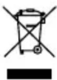
The connection according T568B schema is a straight trough connection (pin 1 to 1, pin 2 to 2, etc).
RJ-45 Pin RJ-45 Pin
1 ____ White/Orange ____ 1
2 ____ Orange ____ 2
3 ____ White/Green ____ 3
4 ____ Blue ____ 4
5 ____ White/Blue ____ 5
6 ____ Green ____ 6
7 ____ White/Brown ____ 7
8 ____ Brown ____ 8
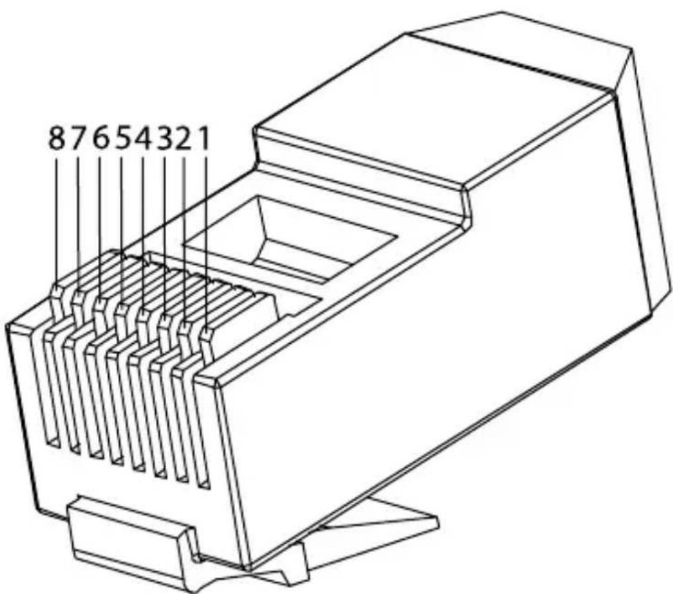
text_image
87654321DECLARATION OF CONFORMITY
Hereby, Marmitek BV, declares that this MegaView50&51 is in compliance with the essential requirements and other relevant provisions of the following Directives:
DIRECTIVE 2004/108/EC OF THE EUROPEAN PARLIAMENT AND OF THE COUNCIL of 15 December 2004 on the approximation of the laws of the Member States relating to electromagnetic compatibility
Directive 2002/95/EC of the European Parliament and of the Council of 27 January 2003 on the restriction of the use of certain hazardous substances in electrical and electronic equipment
DECLARATION OF CONFORMITY
Hereby, Marmitek BV, declares that this MegaView51 is in compliance with the essential requirements and other relevant provisions of the following Directives:
Directive 2006/95/EC of the European Parliament and of the Council of 12 December 2006 on the harmonisation of the laws of Member States relating to electrical equipment designed for use within certain voltage limits
Marmitek is a trademark of Marmidenko B.V. - MegaView50 and MegaView51 are trademarks of Marmitek B.V.
All rights reserved.
Copyright and all other proprietary rights in the content (including but not limited to model numbers, software, audio, video, text and photographs) rests with Marmitek B.V. Any use of the Content, but without limitation, distribution, reproduction, modification, display or transmission without the prior written consent of Marmitek is strictly prohibited. All copyright and other proprietary notices shall be retained on all reproductions.