FBS 43 A1 - Lawn mower FLORABEST - Free user manual and instructions
Find the device manual for free FBS 43 A1 FLORABEST in PDF.
| Technical Specifications | FLORABEST FBS 43 A1 lawn mower, petrol engine, cutting width 43 cm, adjustable cutting height from 25 to 75 mm. |
|---|---|
| Engine Type | 4-stroke petrol engine, power 1.6 kW. |
| Tank Capacity | Fuel tank capacity of 1.2 L. |
| Weight | Approximately 30 kg. |
| Usage | Ideal for medium-sized gardens, use on flat to slightly sloping terrain. |
| Maintenance | Regularly check oil level, clean air filter, sharpen blades. |
| Repair | Consult the user manual for troubleshooting procedures, spare parts available. |
| Safety | Wear safety glasses, do not use in rain, follow safety instructions in the manual. |
| General Information | 2-year warranty, after-sales service available, compatible accessories: collection bag, engine oil. |
Frequently Asked Questions - FBS 43 A1 FLORABEST
User questions about FBS 43 A1 FLORABEST
0 question about this device. Answer the ones you know or ask your own.
Ask a new question about this device
Download the instructions for your Lawn mower in PDF format for free! Find your manual FBS 43 A1 - FLORABEST and take your electronic device back in hand. On this page are published all the documents necessary for the use of your device. FBS 43 A1 by FLORABEST.
USER MANUAL FBS 43 A1 FLORABEST
Operation and Safety Notes
Original operating instructions
IAN 87780
FRCH
Before reading, unfold the page containing the illustrations and familiarise yourself with all functions of the device.
Operation and Safety Notes


-3


-4


DE/AT/CH
Inhaltsverzeichnis
2006/42/EC
Annex IV
Notified Body:
Notified Body No.:
Reg.No.:
2000/14/EC_2005/88/EC
Annex V
Annex VI
Noise measured: L_max = 104.7 dB (A); guaranteed L_max = 110 dB (A)
P=1,35KW;L/0=cm
Notified Body:
2004/26/EC
Emission No.:e11'97/68SA'2004/26'1181'00
Standard references: EN ISO 11806; EN ISO 14982
Subject to change without notice
Archive-File/Record: NAPR006181
Documents registrar: Robert Mayn
Wiesenweg 22, D-94405 Landau/Isar
DE/AT/CH
14.Garantieurkunde
(Commande, stockage, verification)
2006/42/EC
Annex IV
Notified Body:
Notified Body No.:
Reg.No.:
2000/14/EC_2005/88/EC
Annex V
Annex VI
Noise measured: L = 104.7 dB (A); guaranteed L = 110 dB (A)
P=1.35KW L/Q=cm
Notified Body:
2004/26/EC
Emission No.: e11'97/68SA'2004/26'1181'00
Archive-File/Record: NAPR006181
Documents registrar: Robert Mayn
Wiesenweg 22, D-94405 Landau/Isar
Standard references: EN ISO 11806; EN ISO 14982
Subject to change without notice
FR/CH
14. Bon de garantie
Chere Cilente, Cher Client
2006/42/EC
Annex IV
Notified Body:
Notified Body No.:
Reg.No.:
2000/14/EC_2005/88/EC
Annex V
Annex VI
Noise measured: L_max = 104.7 dB (A); guaranteed L_max = 110 dB (A)
P=1.35KW;L/0=cm
Notified Body:
2004/26/EC
Emission No.: e11'97/68SA'2004/26'1181'00
Archive-File/Record: NAPR006181
Documents registrar: Robert Mayn
Wiesenweg 22, D-94405 Landau/Isar
Standard references: EN ISO 11806; EN ISO 14982
Subject to change without notice
IT/CH
2006/42/EC
Annex IV
Notified Body:
Notified Body No.:
Reg.No.:
2000/14/EC_2005/88/EC
Annex V
Annex VI
Noise measured: L_m = 104.7 dB (A); guaranteed L_m = 110 dB (A)
P=1.35KW; L/0=cm
Notified Body:
2004/26/EC
Emission No.: e11'97/68SA'2004/26'1181'00
Archive-File/Record: NAPB006181
Documents registrar: Robert Mayn
Wiesenweg 22, D-94405 Landau/Isar
Standard references: EN ISO 11806; EN ISO 14982
Subject to change without notice
NL
14.Garantiebewijs
Geachte klant,
- Introduction 74
- Safety regulations 74
- Layout and items supplied 77
- Intended use 77
- Technical data 78
6.Before starting the equipment 78 - Operation 80
- Maintenance and ordering of spare parts.. 82
- Storage and transport 84
- Cleaning 84
- Disposal and recycling 84
12.Troubleshooting. 85
13.Declaration of conformity. 86
14.Warranty certificate. 87
The reprinting or reproduction by any other means, in whole or in part, of documentation and papers accompanying products is permitted only with the express consent of the iSC GmbH.
Subject to technical changes
GB
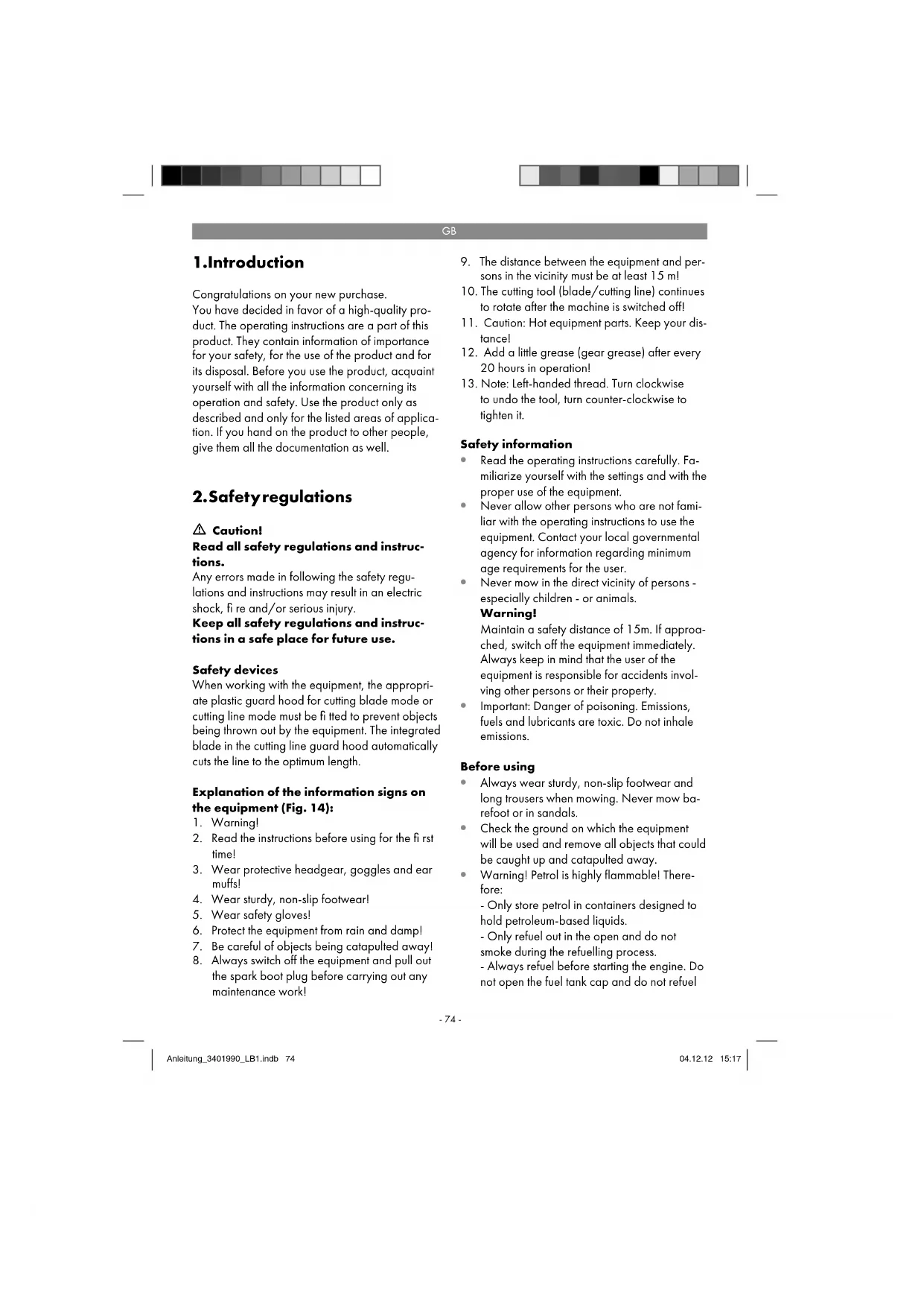
1.Introduction
Congratulations on your new purchase.
You have decided in favor of a high-quality product. The operating instructions are a part of this product. They contain information of importance for your safety, for the use of the product and for its disposal. Before you use the product, acquaint yourself with all the information concerning its operation and safety. Use the product only as described and only for the listed areas of application. If you hand on the product to other people, give them all the documentation as well.
2. Safety regulations

Caution!
Read all safety regulations and instructions.
Any errors made in following the safety regulations and instructions may result in an electric shock, fire and/or serious injury.
Keep all safety regulations and instructions in a safe place for future use.
Safety devices
When working with the equipment, the appropriate plastic guard hood for cutting blade mode or cutting line mode must be fitted to prevent objects being thrown out by the equipment. The integrated blade in the cutting line guard hood automatically cuts the line to the optimum length.
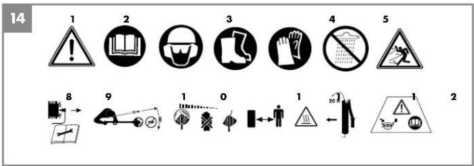
Explanation of the information signs on the equipment (Fig. 14):
- Warning!
- Read the instructions before using for the first time!
- Wear protective headgear, goggles and ear muffs!
- Wear sturdy, non-slip footwear!
- Wear safety gloves!
- Protect the equipment from rain and damp!
- Be careful of objects being catapulted away!
-
Always switch off the equipment and pull out the spark boot plug before carrying out any maintenance work!
-
The distance between the equipment and persons in the vicinity must be at least 15 m!
- The cutting tool (blade/cutting line) continues to rotate after the machine is switched off!
- Caution: Hot equipment parts. Keep your distance!
- Add a little grease (gear grease) after every 20 hours in operation!
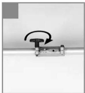
- Note: Left-handed thread. Turn clockwise to undo the tool, turn counter-clockwise to tighten it.
Safety information
- Read the operating instructions carefully. Familiarize yourself with the settings and with the proper use of the equipment.
- Never allow other persons who are not familiar with the operating instructions to use the equipment. Contact your local governmental agency for information regarding minimum age requirements for the user.
- Never mow in the direct vicinity of persons - especially children - or animals.
Warning!
Maintain a safety distance of 15m . If approached, switch off the equipment immediately. Always keep in mind that the user of the equipment is responsible for accidents involving other persons or their property.
Important: Danger of poisoning. Emissions, fuels and lubricants are toxic. Do not inhale emissions.
Before using
Always wear sturdy, non-slip footwear and long trousers when mowing. Never mow barefoot or in sandals.
- Check the ground on which the equipment will be used and remove all objects that could be caught up and catapulted away.
- Warning! Petrol is highly flammable! Therefore:
- Only store petrol in containers designed to hold petroleum-based liquids.
-Only refuel out in the open and do not
smoke during the refuelling process. - Always refuel before starting the engine. Do not open the fuel tank cap and do not refuel
GB
while the engine is running or when the equipment is hot.
-
If petrol has overflowed, do not under any circumstances attempt to start the engine. Instead, remove the equipment from the affected area. Avoid starting the engine until the petrol fumes have completely evaporated. For safety reasons, the petrol tank and the tank cap must be replaced if they are damaged.
-
Replace defective silencers.
Before using the scythe, visually inspect it to ensure that the blade, mounting bolts and the entire cutting apparatus are in good working order (i.e. not worn out or damaged). To prevent any imbalance, replace worn out or damaged blades and mounting bolts as a set only (if applicable).
Handling
(operatior, storage, monitoring)
- Wear close-fitting work clothing which is in good condition and which offers protection, such as long trousers, sturdy work shoes, hard-wearing gloves, a helmet, a face mask or goggles to protect your eyes, and good quality cotton wool in your ears or some other ear protectors to reduce the noise.
- Store the equipment in a safe place. Open the petrol tank cap slowly to release any pressure that may have formed in the petrol tank. To prevent the risk of fire, move at least 3 meters from the refueling area before you start the equipment.
- Switch off the equipment before you put it down.
Always hold the equipment firmly in both hands. Your fingers and thumbs should be wrapped around the handles. - Ensure that all screws and connecting elements are secure. Never use the equipment if it has not been properly adjusted or has not been fully or safely assembled.
Make sure that the handles are clean and dry and that there is no petrol mixture on them. -
Set the line spool to the required height. Avoid touching small objects such as stones with the line spool.
-
When carrying out mowing work on a slope always stand at a lower level than the cutting tool. Never cut or trim on a smooth, slippery hill or slope.
- Keep all parts of your body and items of clothing away from the line spool when you start the engine and when the engine is running. Before you start the engine ensure that the line spool will not strike an obstacle.
Always switch off the engine before working on the cutting tool. - Store the equipment and accessories in a safe place protected from naked flames and heat/ spark sources such as gas geyser heaters, tumble dryers, oil stoves or portable radiators, etc.
- Keep the guard hood, line spool and engine clear of mowing debris at all times.
Only adequately trained people and adults may use, adjust and maintain the equipment.
If you are not familiar with the equipment, practice handling it with the engine off.
Always check the site you want to mow before you begin your work. Solid objects such as pieces of metal, bottles, stones, etc. can be catapulted away and cause serious injuries and permanent damage to the equipment. If you touch a solid object with the equipment by mistake, switch off the engine immediately and check the equipment for signs of damage. Never use the equipment if it is damaged or defective.
Always operate the equipment in its high speed range for trimming and cutting. Do not let the engine run at low speed at the start of mowing or during trimming work.
Only use the equipment for the purpose for which it is intended, such as trimming and mowing weeds. - Never hold the line spool above knee height when the equipment is in operation.
Do not use the equipment if other people or animals are in the immediate vicinity. Keep a minimum distance of 15m between yourself and other people or animals when mowing. Keep a distance of 30m if you are mowing down to the ground.
GB
Additional instructions
- Do not use any fuel other than that recommended in the operating instructions. Always follow the instructions in the section "Fuel and oil". Do not use petrol that has not been mixed correctly with 2-stroke oil. Otherwise there is a risk of causing permanent damage to the engine and of voiding the manufacturer's guarantee.
- Do not smoke while refueling or using the equipment.
- Never use the equipment without the exhaust pipe.
- Do not touch the exhaust pipe with your hands or body. Hold the equipment so that your fingers and thumbs are wrapped around the handled
- Do not use the equipment in an uncomfortable posture, off balance, with extended arms or with only one hand. Always use both hands on the equipment and wrap your fingers and thumbs around the handles.
Always keep the line spool on the ground whilst the equipment is in operation.
Use the equipment only for the purpose for which it is intended, such as trimming and mowing weeds. - Do not use the equipment over a lengthy period of time - take regular breaks.
- Do not use the equipment when under the influence of alcohol or drugs.
Use the equipment only when the guard hood is fitted and in good working order.
Any modifications to the product may place your personal safety at risk and cause the manufacturer's warranty to be voided. -
Never use the equipment near inflammable liquids or gases, neither in enclosed rooms nor outdoors. This may cause explosions and/or fire.
-
Do not use any other cutting tools. For your own safety you must use only the accessories and attachments which are listed in the operating instructions or which are recommended or specified by the manufacturer. The use of cutting tools or accessories other than those recommended in the operating instructions or catalog may place your personal safety at risk.
Safety precautions for handling the blade
Take not of all warnings and instructions relating to operating and fitting the blade.
The blade can recoil suddenly from objects if it cannot cut or mow through them. This can cause injuries to the arms or legs. Keep bystanders and animals at least 15m away from where you are working. If the equipment strikes a foreign body, stop the engine immediately and wait for the blade to come to a standstill. Check the blade for signs of damage. Always replace the blade if it is bent or cracked.
The blade is liable to catapult away objects with high force. This can cause blindness or injuries. Wear protection on your eyes, face and legs. Always remove objects from your working area before you use the blade.
- Carefully check the equipment and its fittings for signs of damage every time before use. Do not use the equipment unless all the blade fittings are installed correctly.
- When you release the throttle lever, the blade will continue to rotate and will only gradually come to a standstill. A blade which is in the process of rotating to a standstill can cause you or bystanders injuries through cutting. Before you start any work on the blade, switch off the engine and ensure that the blade has come to a standstill.
The danger zone has a radius of 15 meters. Bystanders may suffer blindness or injuries. Keep a distance of 15 meters between yourself and other people or animals.
GB
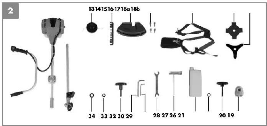
3. Layout and items supplied
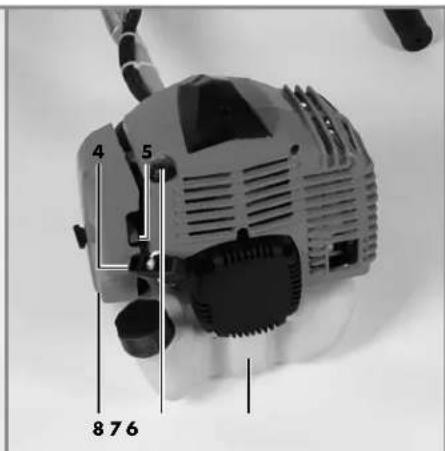
3.1 Layout (Fig. 1-13)
-
Connecting piece for long handle
-
Long handle
-
Steady grip
-
Starter line / starter cable
-
Choke lever
-
Petrol tank
-
Fuel pump "primer"
-
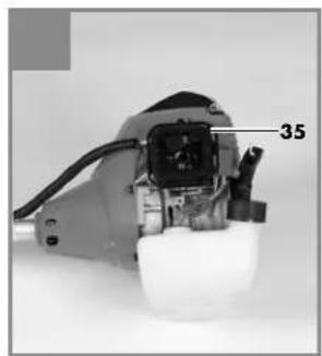
Air filter housing cover
-
On/Off switch
-
Throttle lever lock
-
Throttle lever
-
Throttle lock
-
Line spool with cutting line
-
Cutting line guard hood
-
Cutting blade guard hood
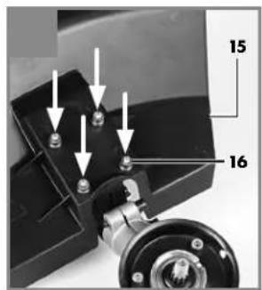
16.Screw M5 (4x)
- Carrying strap
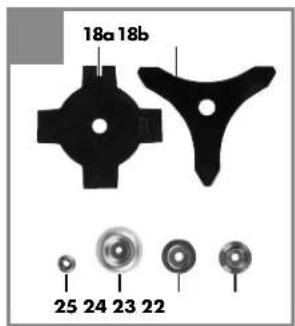
18a.Cutting blade (4 teeth)
18b. Cutting blade (3 teeth)
-
Holder for steady grip
-
Handle screw M8
21.Washer 8mm
-
Carrier plate
-
Pressure plate
-
Pressure plate cover
-
Nut M10 (left-hand thread)
-
Oil/petrol mixing bottle
-
Spark plug wrench
-
Open-ended wrench 8/10 mm
-
Hex wrench 4 mm
-
Hex wrench 5 mm
-
Protective cap for spark boot plug
-
Handle screw M6
-
Nut M6
34.Washer 6mm
-
Air filter
-
Spark boot plug
The cutting blade (18a/18b) and the line spool
(13) are jointly referred to in the text as the cutting tool (generic term).
3.2 Items supplied
- Open the packaging and take out the equipment with care.
- Remove the packaging material and any packaging and/or transportation braces (if available).
Check to see if all items are supplied.
Inspect the equipment and accessories for transport damage.
If possible, please keep the packaging until the end of the guarantee period.
Important!
The equipment and packaging material are not toys. Do not let children play with plastic bags, foils or small parts. There is a danger of swallowing or suffocating!
4.Intendeduse
The equipment (cutting blade mode) is designed for cutting high grass and sparse scrub with the 4-tooth blade and for cutting dense scrub and slender wood growth with the 3-tooth blade. The equipment (line spool mode) is designed for cutting lawns and small weeds. The operating instructions as supplied by the manufacturer must be obeyed to ensure that the equipment is used properly.
Any use which is not expressly permitted in these instructions may result in damage to the equipment and place the user in serious danger. Be sure to observe the restrictions in the safety information.
Please note that our equipment has not been designed for use in commercial, trade or industrial applications. Our warranty will be voided if the equipment is used in commercial, trade or industrial businesses or for equivalent purposes.
Caution! Due to the high risk of physical injury to the user, the equipment must not be used to carry out the following work: to clean dirt and debris off walkways, or to chop up tree or hedge clippings. Similarly, the equipment must not be used to level out high areas such as molehills. For safety rea
GB
sons, the equipment is not allowed to be used as a drive unit for other tools of any kind.
The equipment is allowed to be used only for its intended purpose. Any other use is deemed to be a case of misuse. The user/operator and not the manufacturer will be liable for any damage or injuries of any kind resulting from such misuse.
5. Technical data
Engine type
2-stroke engine, air-cooled, chrome cylinder
Engine power (max.) 1.35 kW/1.8 hp
Displacement .42.7 ccm
Idle engine speed .3000 min Max. engine speed
with blade ..9000 min with line spool ..8400 min Max. cutting speed with blade ..6800 min with line spool ..6300 min Ignition Electronic Drive Centrifugal clutch Weight (with empty tank) .7.5 kg Cutting circle diameter of line ..41 cm Cutting circle diameter of blade ..23 cm Cutting line length ..8.0 m Cutting line diameter ..2.0 mm Tank capacity ..0.8 Spark plug Champion RCJ6Y Fuel consumption at max. engine power ..0.6 kg/h Specific fuel consumption at max. engine power ..446 g/kWh
Sound and vibration
LpA sound pressure level .98 dB(A)
Kuncertainty 1.5 dB
Lwa sound power level 110 dB(A)
Kuncertainty 1.5 dB
Wear ear-muffs.
The impact of noise can cause damage to hearing.
Operation
Vibration emission value a_h = 4.1 m/s^2 K uncertainty = 1.5 m/s²
Keep the noise emissions and vibrations to a minimum.
Only use appliances which are in perfect working order.
Service and clean the appliance regularly.
Adapt your working style to suit the appliance.
Do not overload the appliance.
Have the appliance serviced whenever necessary.
- Switch the appliance off when it is not in use.
- Wear protective gloves.
6. Before starting the equipment
6.1 Assembly
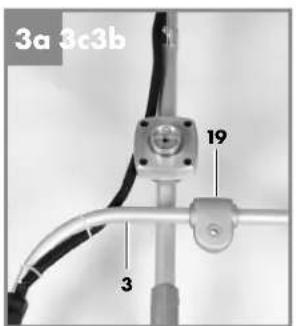
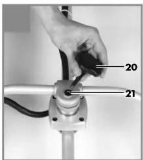
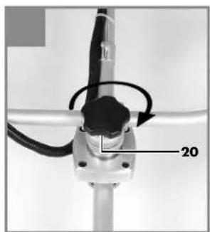
6.1.1 Fitting the steady grip (Fig. 3a-3c)
Fit the steady grip (3) as shown in Figures 3a-3c. Do not tighten the screw (20) until you have set the optimum working position with the carrying strap (17) (see also section 6.2). The steady grip should be aligned as shown in Figure 1. To dismantle, proceed in reverse order.
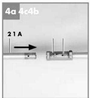
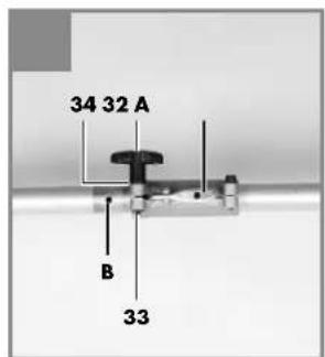
6.1.2 Fitting the long handle (Fig. 4a-4c)
Pass the handle screw (32) through the washer (34) and into the connecting piece of the long handle (1). Secure the handle screw loosely with the nut (33). Now press the locking lever (A) and push the long handle (Fig. 4a/Item 2) carefully into the connecting piece for the long handle. While doing so, ensure that the drive shafts on the inside of the long handle slide into each other (turn the line spool (13) / cutting blade (18a/18b) gently if required). The lug of the locking lever (A) must latch into the hole (B). Now tighten the handle screw as shown in Figure 4c. To
GB
dismantle, simply slacken the handle screw and actuate the locking lever.
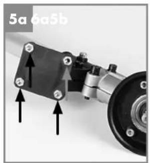
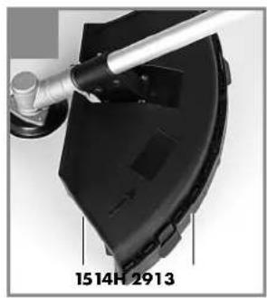
6.1.3 Fitting the blade guard hood
Important: The cutting blade guard hood (15) must be fitted when you want to work with the cutting blade.
The guard hood for the cutting blade must be installed as shown in Figures 5a - 5b.
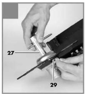
6.1.4 Fitting/Replacing the cutting blade
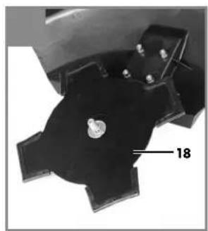
The procedure for fitting the cutting blade (18a/18b) is shown in Figures 6a-6g. To dismantle, proceed in reverse order.
- Fit the carrier plate (22) onto the spline shaft as shown in Figure 6b.
- Secure the cutting blade (18a/18b)) on the carrier plate (Fig. 6c).
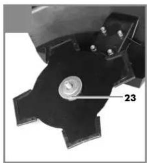
- Place the pressure plate (23) over the thread of the spline shaft (Fig. 6d).
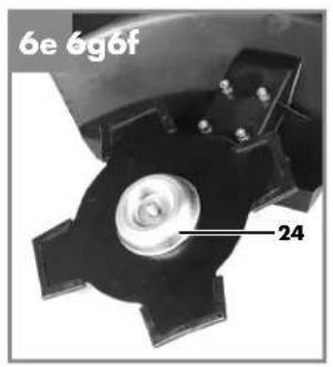
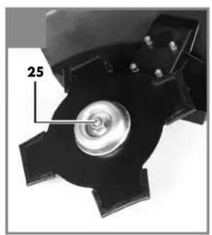
Plug on the cover of the pressure plate (24) (Fig. 6e). - Look for the hole in the carrier plate, line up with the notch underneath, lock with the supplied hex wrench (29), and then tighten the nut (25) with the spark plug wrench (27) (Fig. 6f/6g). Important: Left-hand thread
The cutting blades (18a/18b) are delivered with plastic protective caps fitted to them. Remove these caps before use and refit them after use.
6.1.5 Fitting the cutting line guard hood on the cutting blade guard hood
Important: The cutting line guard hood (14) must be fitted in addition when you want to work with the cutting line.
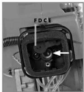
The guard hood for the cutting line must be installed as shown in Figures 7a-7b. Make sure that the cutting line guard hood engages correctly. A blade (Fig. 7a/Item F) on the underside of the guard hood automatically cuts the cutting line to the optimum length. It is covered by a guard (Fig. 7a/Item G).
Remove the guard before you start working and replace it when you have finished working.
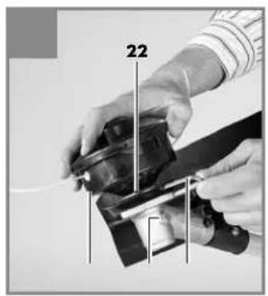
6.1.6 Fitting/Replacing the line spool
The procedure for fitting the line spool (13) is shown in Figure 7c. To dismantle, proceed in reverse order. The line spool is already fitted when the equipment is delivered.
Look for the hole in the carrier plate (22), line up with the notch beneath it, lock with the supplied hex wrench (29), and screw the line spool onto the thread.
Important: Left-hand thread
6.2 Setting the cutting height
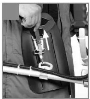
Fit the carrying strap (17) as shown in Figures 8a-8c.
- Hook the equipment to the carrying belt (Fig. 8d).
Adjust to the perfect working and cutting position using the various strap adjusters on the carrying strap (Fig. 8e).
To confirm the optimum length of the carrying strap, make a few swinging movements with the engine off (Fig. 9a).
The carrying strap is fitted with a quick-release mechanism. Pull the red strap section (Fig. 8f) if you need to remove the strap quickly.
Important: Always use the strap when working with the equipment. Attach the strap as soon as you have started the engine and it is running in idle mode. Switch off the engine before you take off the carrying strap.
6.3 Fuel and oil
Recommended fuels
Use only a mixture of unleaded petrol and special 2-stroke engine oil.
Mix the fuel mixture as indicated in the fuel mixing table.
Important: Do not use a fuel mixture which has been stored for longer than 90 days.
Important: Never use 2-stroke oil with a recommended mixing ratio of 100:1. The manufacturer's warranty will be voided in case of engine damage due to inadequate lubrication.
Important: Only use containers designed and approved for the purpose to transport and store
GB
fuel. Pour the correct quantities of petrol and 2-stroke oil into the mixing bottle (see scale printed on the bottle). Then shake the bottle well.
6.4 Fuel mixing table
Mixing procedure: 40 parts petrol to 1 part oil
| Petrol 2-stroke oil | |
| 1 liter 25 ml | |
| 5 liters 125 ml | |
7. Operation
Please note that the statutory regulations governing noise abatement may differ from one location to another.
Each time before use, check the following :
- That there are no leaks in the fuel system.
- That the equipment is in perfect condition and that the safety devices and cutting devices are complete.
- That all screws are securely fastened.
- That all moving parts move smoothly.
7.1 Starting the engine when cold
Fill the tank with the oil/petrol mix. See also "Fuel and oil".
- Set the equipment down on a hard, level surface.
- Press the fuel pump (primer) (Fig. 1/Item 7) 10 times.
- Move the On/Off switch (Fig. 1/Item 9) to
- Secure the throttle lever (Fig. 1 / Item 11). To do this, press the throttle lever lock (Fig. 1/Item 12) and then press the throttle lever (Fig. 1/Item 11) and lock the throttle lever by pressing the lock (Fig. 1/Item 10) at the same time.
- Set the choke lever (Fig. 1/Item 5) to "
- Hold the equipment firmly and pull out the starter cable (Fig. 1/Item 4) until you feel it begin to resist. Then tug sharply on the starter cable 4 times. The equipment should start. Important: Never allow the starter line to snap back. This may result in damage.
Important: Since the throttle lever is secured, the cutting tool starts to operate when the engine is started.
Then release the throttle lever by actuating it once. Actuating the throttle lever will also release the choke lever. (The engine returns to its idle state).
- If the engine does not start up, repeat steps 4-6 above.
Please note: If the engine does not start up even after several attempts, read the section Troubleshooting".
Please note: Always pull out the starter cable in a straight line. If it is pulled out at an angle, friction will occur on the eyelet.
As a result of this friction, the starter line will become frayed and will wear away faster.
Always hold the starter cable when the starter line retracts.
Never allow the starter line to snap back when it has been pulled out.
7.2 Starting the engine when warm
(The equipment has been idle for less than 15-20 min.)
- Set the equipment down on a hard, level surface.
- Switch the On/Off switch to "1" (Fig. 1 / Item 9).
- Secure the throttle lever (Fig. 1 / Item 11) (in the same way as described in "Starting the engine when cold").
- Hold the equipment firmly and pull out the starter cable until you feel it start to resist. Then tug sharply on the starter cable. The equipment should start after 1-2 tugs. If the equipment does not start after 6 tugs, repeat steps 1-7 of the procedure for starting the engine from cold.
GB
7.3 Switching off the engine
Emergency Stop procedure:
If it becomes necessary to stop the equipment immediately, set the On/Off switch (9) to "Stop" or "0".
Normal procedure:
Let go of the throttle lever (11) and wait until the engine has changed to idling speed. Then set the On/Off switch (9) to "Stop" or "0".
7.4 Practical tips
Practice all the work steps with the engine switched off before you start to use the equipment.
Warning! Take extreme care during mowing work. When doing such work keep a distance of 30 meters between yourself and other people or animals.
Extending the cutting line
Warning! Do not use any kind of metal wire or metal wire encased in plastic in the line spool. This may cause serious injuries to the user. To extend the cutting line (13), run the engine at full speed and tap the line spool on the ground. This will automatically extend the line. The blade on the guard hood will cut the line to the permissible length (Fig. 9b).
Important: Remove all grass and weed remnants at regular intervals to prevent the equipment from overheating.
Grass and weed remnants become trapped under the guard hood (Fig. 9c) and prevent the equipment from cooling sufficiently. Remove the remnants carefully using a screwdriver or the like.
Different cutting methods
When the equipment is correctly assembled it will cut weeds and long grass in places which are difficult to access, e.g. along fences, walls and foundations and also around trees. It can also be used for "mowing" down vegetation so that a garden can be better prepared or a certain area cleared down to the soil.
Please note: Even if it is used carefully, cutting around foundations, stone or concrete walls, etc. will result in the line suffering more than the normal level of wear.
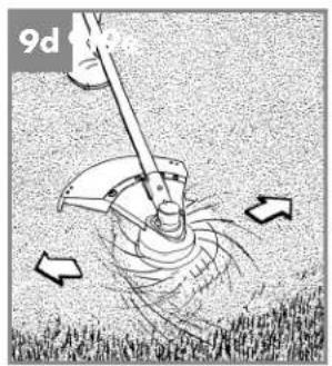
Trimming/mowing (with line spool/cutting blade)
Swing the equipment from side to side in a scything motion. Always keep the cutting tool parallel to the ground.
Check the site and decide which cutting height you require. Guide and hold the cutting tool at the required height to ensure that you cut evenly (Fig. 9d).
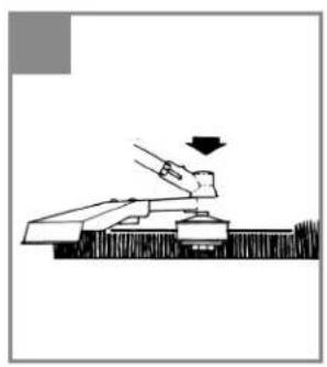
Low trimming (with line spool)
Hold the equipment right in front of you at a slight angle so that the underside of the line spool is above the ground and the line strikes the correct target. Always cut away from yourself. Never draw the equipment towards yourself.
Cutting along fences/foundations (with line spool)
Approach wire mesh fences, lath fences, natural stone walls and foundations slowly so that you can cut close to them without striking the obstacle with the line. If, for example, the line strikes stones, stone walls or foundations, it will wear or fray. If the line strikes wire fencing, it will break.
Trimming around trees (with line spool)
When trimming around tree trunks, approach slowly so that the line does not strike the bark. Walk around the tree and take care not to damage the tree. Approach grass or weeds with the tip of the line and tilt the line spool forwards slightly.
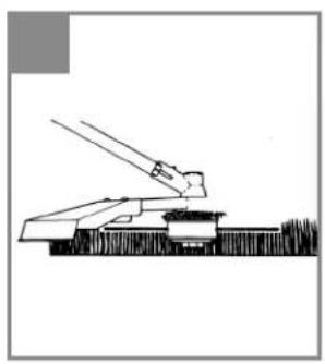
Mowing down to the ground (with line spool)
When mowing down to the ground you will cut all the vegetation. To do this, set the line spool at an angle of 30^ to the right. Place the handle in the required position (Fig. 9e).
Caution! Increased risk of injury to the user, bystanders and animals, and increased risk of damaging property due to objects (e.g. stones) being catapulted away.
GB
Caution! Do not use the equipment to remove objects from footpaths, etc.
The petrol scythe is a powerful tool and can catapult small stones and other objects a distance of 15 meters or more, causing injuries and damage to cars, houses and windows.
Sawing
The equipment is not suitable for sawing.
Jamming
If the cutting tool jams as a result of attempting to cut vegetation that is too dense, switch off the engine immediately. Remove the grass and scrub from the equipment before you restart it.
Preventing recoil
When you work with the blade, there is a risk of recoil if it strikes solid objects (tree trunks, branches, tree stumps, stones or the like). This will throw the equipment backwards in the direction opposite to the rotation of the cutting tool. This can cause you to lose control of the equipment. Do not use the blade near fences, metal posts, boundary stones or foundations. For cutting slender wood growth, position the equipment as shown in Fig. 9f in order to prevent recoil.
8. Maintenance and ordering of spare parts
Always switch off the equipment and pull out the spark boot plug (36) before carrying out any maintenance work.
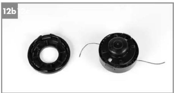
8.1 Replacing the line spool/ cutting line
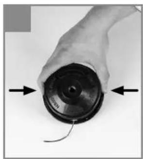
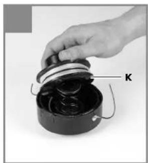
- Dismantle the line spool (13) as described in section 6.1.6. Press the spool together (Fig. 12a) and remove one half of the housing (Fig. 12b).
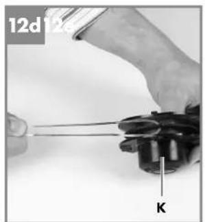
- Take the spool plate (K) out of the line spool housing (Fig. 12c).
- Remove any remaining cutting line.
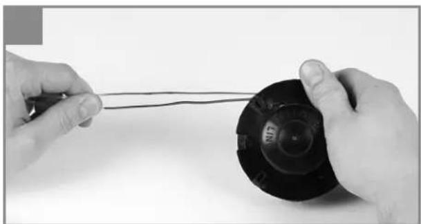
- Place the new cutting line in the center and hang the loop which has formed into the recess in the spool splitter. (Fig. 12d)
- Wind up the line counter-clockwise and under
GB
8.3 Maintenance of the spark plug
Electrode gap = 0.6mm (distance between the electrodes between which the ignition spark is created). Tighten the spark plug with 12 to 15Nm using a torque wrench (available from your dealer). Check the spark plug for dirt and grime after 10 hours of operation and if necessary clean it with a copper wire brush. Thereafter service the spark plug after every 50 hours of operation.
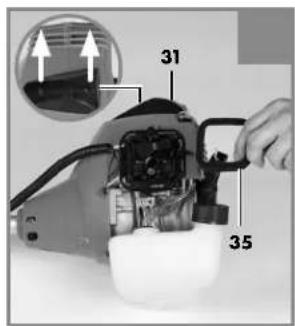
- Dismantle the protective cap (Fig. 10c/Item 31) using a screwdriver.
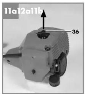
- Pull off the spark boot plug (Fig. 11a/Item 36).
- Remove the spark plug (Fig. 11b) with the supplied spark plug wrench (27).
- Assemble in reverse order.
8.4 Sharpening the guard hood blade
The guard hood blade (Fig. 7a/Item F) can become blunt over time. If you notice this, undo the two screws holding the guard hood blade to the guard hood. Clamp the blade in a vise. Sharpen the blade with a fl at fi le and make sure that the angle of the cutting edge is not altered in the process. File in one direction only.
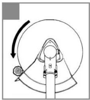
8.5 Carburetor settings
Important: Settings on the carburetor are allowed to be made by authorized customer service personnel.
The air filter housing cover must be removed before any work on the carburetor, as shown in Figures 10a and 10b.
Setting the throttle cable:
If the maximum speed of the equipment drops over time and you have ruled out all the other possible causes listed in the section "Troubleshooting", it may be necessary to adjust the throttle cable.
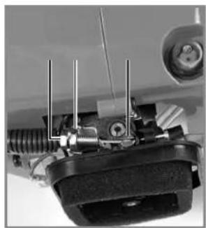
First of all check whether the carburetor opens fully when the throttle lever is pressed right through. This is the case if the carburetor slide (Fig. 13a/Item F) is completely opened when the throttle is fully activated.
Figure 13a shows the correct setting. If the carburetor slide is not completely open, it must be
adjusted.
The following steps are required to adjust the throttle cable:
- Undo the lock nut (Fig. 13b/Item C) a few turns.
- Undo the adjusting screw (Fig. 13b/Item D) until the carburetor slide is completely open when the throttle is fully activated, as shown in Figure 13a.
Retighten the lock nut.
Setting the idling speed:
Caution! Set the idling speed when the equipment is warm.
If the engine stalls when the throttle is not pressed and you have ruled out all the other possible causes listed in the section, Troubleshooting, the idling speed must be adjusted. To do this turn the idling speed screw (Fig. 13b/Item E) clockwise until the equipment runs smoothly at idling speed. If the idling speed is so fast that the cutting tool turns as well, it has to be reduced by turning the idling speed screw for as long as is required for the cutting tool to stop turning as well.
8.6 Applying grease to the gear unit
Add a little gear grease (approx. 10 g) after every 20 hours in operation. To do so, open the screw H (Fig. 7c).
8.7 Environmental protection
Dispos of soiled maintenance material and operating materials at the appropriate collection point.
Recycle packaging material, metal and plastics.
8.8 Ordering replacement parts
Please provide the following information on all orders for spare parts:
Type of unit
Article number of the unit
ID number of the unit
For current prices and information please visit www.isc-gmbh.info
GB
9. Storage and transport
9.1 Storage
Important: Never put the equipment into storage for longer than 30 days without carrying out the following steps.
9.2 Transport
To transport the equipment, empty the petrol tank as described in the section "Storage". Clean coarse dirt off the equipment with a brush or hand brush. Dismantle the steady grip and the long hande as described in section 6.1.1 and 6.1.2.
Storing the equipment
If you intend to store the equipment for longer than 30 days, it must be prepared accordingly. Otherwise the fuel still remaining in the carburetor will evaporate and leave a rubbery sediment. This can cause problems when starting up the equipment and may require expensive repairs.
- Slowly remove the fuel tank cap to release any pressure that may have formed in the tank. Carefully empty the tank (6).
- To remove the fuel from the carburetor, start the engine and let it run until the equipment stops.
- Leave the engine to cool (approx. 5 minutes).
- Remove the spark plug (see 8.3).
- Add one teaspoon of 2-stroke engine oil into the combustion chamber. Slowly pull the starter cord several times to apply a layer of oil to all internal components. Fit the spark plug again.
Note: Store the equipment in a dry place and far away from possible ignition sources such as an oven, a gas-fi red hot water boiler, a gas-fi red dryer, etc.
10.Cleaning
Always switch off the equipment and pull out the spark boot plug before carrying out any cleaning work.
The equipment should be cleaned thoroughly every time after it has been used. This applies particularly to the cutting tool and the guard hoods.
- Keep the air vents and the motor housing free of dirt and dust as far as possible. Wipe the equipment with a clean cloth or blow it down with compressed air at low pressure.
It is easiest to remove dirt and grass immediately after mowing.
Clean the equipment regularly with a damp cloth and some soft soap. Do not use cleaning agents or solvents; these may be aggressive to the plastic parts in the equipment. Ensure that no water can get into the interior of the equipment.
11. Disposal and recycling
The equipment is supplied in packaging to prevent it from being damaged in transit. The raw materials in this packaging can be reused or recycled. The equipment and its accessories are made of various types of material, such as metal and plastic. Defective components must be disposed of as special waste. Fuel and oil must be disposed of only at special refuse collection centers. Ask your dealer or your local council.
GB
12.Troubleshooting
| Fault Possible cause Troubleshooting | ||
| The equipment does not start | - Correct starting procedure not followed - Sooted or damp spark plug - Incorrect carburetor setting | - Follow the instructions for starting - Clean the spark plug or replace it with a new one - Contact an authorized customer service outlet or send the equipment to ISC-GmbH |
| The equipment starts but does not develop its full power | - Incorrect choke lever (5) setting - Soiled air fiiter (35) - Incorrect carburetor setting | - Set the choke lever to "" - Clean the air fiiter - Contact an authorized customer service outlet or send the equipment to ISC-GmbH |
| The engine does not run smoothly | - Incorrect electrode gap on the spark plug - Incorrect carburetor setting | - Clean the spark plug and adjust the electrode gap or fit a new spark plug - Contact an authorized customer service outlet or send the equipment to ISC-GmbH |
| Engine smokes excessively | - Incorrect fuel mix - Incorrect carburetor setting | - Use the correct fuel mix (see fuel mixing table) - Contact an authorized customer service outlet or send the equipment to ISC-GmbH |
GB
13. Declaration of conformity
2006/42/EC
Annex IV
Notified Body:
Notified Body No.:
Reg.No.:
2000/14/EC_2005/88/EC
Annex V
Annex VI
Noise measured: L_m = 104.7 dB (A); guaranteed L_m = 110 dB (A)
P=1.35KW; L/0=cm
Notified Body:
2004/26/EC
Emission No.: e11'97/68SA'2004/26'1181'00
Archive-File/Record: NAPR006181
Documents registrar: Robert Mayn
Wiesenweg 22, D-94405 Landau/Isar
Standard references: EN ISO 11806; EN ISO 14982
Subject to change without notice
GB
14.Warrantycertificate
Dear Customer,
All of our products undergo strict quality checks to ensure that they reach you in perfect condition. In the unlikely event that your device develops a fault, please contact our service department at the address shown on this guarantee card. Of course, if you would prefer to call us then we are also happy to offer our assistance under the service number printed below. Please note the following terms under which guarantee claims can be made:
- These guarantee terms cover additional guarantee rights and do not affect your statutory warranty rights. We do not charge you for this guarantee.
- Our guarantee only covers problems caused by material or manufacturing defects, and it is restricted to the rectification of these defects or replacement of the device. Please note that our devices have not been designed for use in commercial, trade or industrial applications. Consequently, the guarantee is invalidated if the equipment is used in commercial, trade or industrial applications or for other equivalent activities. The following are also excluded from our guarantee: compensation for transport damage, damage caused by failure to comply with the installation/assembly instructions or damage caused by unprofessional installation, failure to comply with the operating instructions (e.g. connection to the wrong mains voltage or current type), misuse or inappropriate use (such as overloading of the device or use of non-approved tools or accessories), failure to comply with the maintenance and safety regulations, ingress of foreign bodies into the device (e.g. sand, stones or dust), effects of force or external influences (e.g. damage caused by the device being dropped) and normal wear resulting from proper operation of the device. This applies in particular to rechargeable batteries for which we nevertheless issue a guarantee period of 12 months. The guarantee is rendered null and void if any attempt is made to tamper with the device.
- The guarantee is valid for a period of 3 years starting from the purchase date of the device. Guarantee claims should be submitted before the end of the guarantee period within two weeks of the defect being noticed. No guarantee claims will be accepted after the end of the guarantee period. The original guarantee period remains applicable to the device even if repairs are carried out or parts are replaced. In such cases, the work performed or parts fitted will not result in an extension of the guarantee period, and no new guarantee will become active for the work performed or parts fitted. This also applies when an on-site service is used.
- In order to assert your guarantee claim, please send your defective device postage-free to the address shown below. Please enclose either the original or a copy of your sales receipt or another dated proof of purchase. Please keep your sales receipt in a safe place, as it is your proof of purchase. It would help us if you could describe the nature of the problem in as much detail as possible. If the defect is covered by our guarantee then your device will either be repaired immediately and returned to you, or we will send you a new device.
Of course, we are also happy offer a chargeable repair service for any defects which are not covered by the scope of this guarantee or for units which are no longer covered. To take advantage of this service, please send the device to our service address.

-88-

-89-


IAN:87780 FBS 43 A1
Einhell Germany AG
Wiesenweg 22
D-94405 Landau/Isar
Stand der Informationen · Version des Informations · Versione delle informazioni
Stand van de Informatie · Last Information Update: 12/2012
Ident.-No.: 34.019.90 122012-1
IAN 87780