BL FBS 25 A1 - Lawn mower FLORABEST - Free user manual and instructions
Find the device manual for free BL FBS 25 A1 FLORABEST in PDF.
Frequently Asked Questions - BL FBS 25 A1 FLORABEST
User questions about BL FBS 25 A1 FLORABEST
0 question about this device. Answer the ones you know or ask your own.
Ask a new question about this device
Download the instructions for your Lawn mower in PDF format for free! Find your manual BL FBS 25 A1 - FLORABEST and take your electronic device back in hand. On this page are published all the documents necessary for the use of your device. BL FBS 25 A1 by FLORABEST.
USER MANUAL BL FBS 25 A1 FLORABEST
General Description 6
Delivery Contents 6
Functional Description 6
Summary 6
Safety Functions 7
Technical Specifications .7
Safety Information 8
Symbols in the Instructions 8
Symbols on the Equipment 8
General Safety Information 9
Additional Safety Regulations 11
Assembly 12
Installing the protective cover 12
Fitting the Two-Part Tube 12
Fitting the anti-vibration handle 13
Initial Operation 13
Filling with Fuel 13
Putting on the shoulder strap 14
Starting the Engine 14
Operation 15
Working Notes 15
Cutting grass. 16
Extending the cutting thread 16
If the Equipment Vibrates 16
Care and Maintenance 16
Cleaning the Equipment 17
Changing the Reel 17
Cleaning the Air Filter 17
Changing/Adjusting the Spark Plug .. 18
Sharpening the Thread Cutter 18
Changing the Fuel Filter 18
Winding up the spool 18
Adjusting the Carburettor 19
Removing blockages 19
Checking the coupling 19
Maintenance Intervals 20
Storage 20
General Storage Instructions 20
Storage During Working Breaks 20
Transport 21
Disposal /
Environmental Protection .21
Spare Parts/Accessories 22
Guarantee 23
Repair Service 24
Service-Center 24
Importer 24
Troubleshooting 25
Translation of the original
EC declaration of conformity ......93
Exploded Drawing 100/101
Introduction
Congratulations on the purchase of your new device. With it, you have chosen a high quality product. During production, this equipment has been checked for quality and subjected to a final inspection. The functionality of your equipment is therefore guaranteed.

The operating instructions constitute part of this product. They contain important information on safety, use and disposal.
Before using the product, familiarise yourself with all of the operating and safety instructions. Use the product only as described and for the applications specified. Keep this manual safely and in the event that the product is passed on, hand over all documents to the third party.
Intended Use
The petrol trimmer is suitable for cutting grass in the garden, along border edges and around trees or fence posts.
Any other use not explicitly authorised in these instructions may result in damage to the equipment and represent a serious hazard to the user.
The equipment is not designed for cutting bushes, small trees or similar plants. The equipment is intended for use by adults.
Young people over the age of 16 may use the equipment only under supervision.
The manufacturer is not liable for damages caused by use other than for the intended purpose or by incorrect operation.
General Description

The illustration of the principal functioning parts can be found on the front and back foldout pages.
Delivery Contents
Start by unpacking the equipment and check that it is complete. Dispose of the packaging material correctly.
- Engine part with top shaft tube and multifunction handle
- Bottom shaft tube with mounted thread reel
- Protective cover
- Anti-vibration handle with leg protection
- Carrying strap with body protection
- Maintenance key
100 ml 2-stroke oil - 500 ml oil/petrol mixing bottle
- Instruction Manual
Functional Description
The manually operated and portable petrol trimmer FBS 25 A1 is driven by a combustion engine, which operates without interruption during the work.
The power transmission is by means of a clutch disc, which transmits the output to the cutter via a centrifugal clutch at high speed. As a cutting device, the scythe has a double-thread spool which is equipped with an automatic touch control.
In the cutting process, two plastic wheels rotate about an axis vertical to the cutting level. To protect the user, the equipment has a protective device, which covers the cutting device.
Please refer to the descriptions below for how the operating parts work.
Summary
A 1 Engine housing
2 Spark plug connector
3 Choke lever
4 Starter handle with starter cable
5 Fuel pump (Primer)
6 Air filter cover
7 Fuel tank
8 Multifunction handle
9 Throttle
10 Top shaft tube
11 Anti-vibration handle
12 Leg protection
13 Tube fixing screw
14 Bottom shaft tube
15 Protective cover
16 Thread cutter
17 Reel capsule
18 Thread reel (not visible)
19 Lifting ring for shoulder strap
20 On/off switch
21 Gas locking button
22 Throttle lock
23 Maintenance key
24 100 ml 2-stroke oil
25 500 ml oil/petrol mixing bottle
26 Body protection
27 Shoulder strap
44 Tool bag
B 28 2 screws of the protective cover
29 Shaft holder
30 Transport protection cap
31 Retaining knob of the shaft tube
D 32 4 screws of the anti-vibration handle
33 Retainer of the anti-vibration handle
34Tank cover
F 43 Lug of the quick-release device
35 Fastening screw of the thread spool
36 Thread outlet eye
37 Spring of the thread spool
38 Screw of the air filter cover
39 Air filter housing
40 Air filter
J 41 Spark plug
42 Fuel filter
M 45 Notch in the thread spool
46 Groove in the thread spool
Safety Functions
A 22 Throttle lock
Prevents accidental acceleration of the engine. The throttle can be operated only when the throttle lock is depressed.
20 On/off switch
The on/off switch switches off the engine. It must be in position in order to restart the engine.
15 Protective covers
Protect the operator from accidental contact with the cutting tool and foreign bodies being thrown out.
Technical Specifications
Petrol cutter FBS 25 A1
Engine ....Single-cylinder two-stroke engine Fuel Mix 50:1
Engine capacity 25,4 cm3
Max. engine power ....0.75 kW (1.1 HP)
Engine tick over speed 2800 rpm Max. shaft speed 8500 rpm
Tank capacity 650 ml/cm³
Weight (empty tank) 5.9 kg Metal cutting blade
Threads
Cutting radius. 380 mm
Thread thickness 2 mm
Thread length 5 m
Sound pressure level
(L_pA) 98.2dB(A),K=3dB
Sound power level (L_WA)
Guaranteed 110 dB(A)
Measured 108.2 dB(A); K_WA = 3 dB
Vibration (q_n) 12.93 m/s²; K=1.5 m/s²
Noise and vibration values have been determined according to the standards and regulations mentioned in the declaration of conformity.
Safety Information

In order to be able to operate the equipment safely, all instructions and information in the operating instructions about safety, assembly and operation must be followed precisely. Anyone operating or maintaining this equipment must be familiar with the operating instructions and informed of potential hazards.
Symbols in the Instructions

Warning signs with details for the prevention of personal and property damage.

Command signs (instead of the exclamation mark, the command is explained) with details for the prevention of damage.

Information signs with information for better handling of the equipment.
Symbols on the Equipment
On the equipment, there are information symbols. These convey important information about the product or information about its use.
- Caution: Special safety measures are required when handing the equipment!
The entire operating instructions must be read and understood before use. Non-observance of the operating instructions may be fatal!

Read the operating instructions carefully before using the equipment.

Wear eye protection.

Wear head protection.

Wear ear protection.

Wear protective gloves. Risk of injury from cuts.

Wear safety boots with sturdy soles.

Ensure that the cutting head does not come into contact with foreign bodies when starting or during the work.

Maintain a safety distance of min. 15m from others.

Danger from parts being thrown out! Keep away from other people.

Caution! Fuel and fuel fumes are flammable. Risk of fire and explosion!

Caution! Do work with a thread reel only.

Do not use metallic cutting reels or saw blades. Risk of injury.

Caution! Hot surfaces - risk of burns!

Specification of the guaranteed sound power level L_WA in dB.

Mix ratio 50:1, Use ONLY fuel mix

Use ONLY fuel mix

Cutting circle

Start-up Sequence

Fuel pump (Primer)
General Safety Information
Do not allow access by children or by people who are ill or infirm. Children must be carefully supervised when they are in the area of machinery. Observe the regional and local accident prevention regulations applicable where you are. The same applies for all regulations concerning occupational safety and health in the workplace. The manufacturer cannot be held liable if the machines produced by the same are modified without permission and if damage to people or property occurs as a result of such modifications.

Warning! Always take basic precautions when using machinery. Please also observe all tips and information in the additional safety information.
- Observe the surrounding conditions under which you are working. The motorised equipment produces toxic fumes as soon as the engine is running. These gases may be odourless and invisible. Therefore, never work with the equipment in enclosed or poorly ventilated spaces. Ensure adequate ventilation when working. Ensure a safe stance in the wet, snow and ice, on slopes and on uneven territory.
- Do not allow strangers to use the equipment. Visitors and onlookers - particularly children and people who are ill or infirm - must be kept away from the workplace. Prevent other people from coming into contact with the tools. Do not pass on the equipment to people who are unfamiliar with the equipment and its handling.
- Ensure the safe transport and storage of the equipment. Always carry the equipment suspended by the carrying strap or on the tube. Equipment that is not in use must be stored in a dry place as high up as possible or locked away to be inaccessible.
- Always use the right tool for any work. E.g. do not use small tools or accessories for work that should actually be performed with heavy tools. Use tools only for the purposes for which they have been constructed.
- Ensure appropriate clothing. Clothing must be appropriate and not impede you when working. Wear clothing with cut protection pads.
E O
-
Use personal protective equipment. Wear safety boots with steel caps / steel soles and non-slip soles. Wear a hard hat if there is a risk of falling objects when working.
-
Wear safety goggles. Objects may be thrown out. Serious eye injuries may result.
-
Wear ear protection. Wear personal sound protection, e.g. earplugs.
-
Hand protection. Wear strong gloves - leather gloves offer good protection.
-
Operating the equipment. Never work without the protection on the cutting tool. Risk of injury from objects being thrown out.
-
Remove the socket wrench etc. All keys or similar must be removed before the equipment is switched on.
-
Stay alert at all times. Pay attention to what you are doing. Use your common sense. Do not use motorised tools when you are tired. Work with the equipment must not be carried out under the influence of alcohol, drugs or medications, which impair reactions.
-
Filling with fuel.
-
Always adhere to the current fire regulations and the respective state/federal regulations for fire prevention.
-
Fuel and fuel fumes are highly flammable. Do not fill with fuel when the engine is running or still hot. When filling up, ensure good ventilation. Smoking and open flames are prohibited.
-
Always switch off the engine before filling. Always open the filler cap with care, so any excess pressure present can be relieved slowly and no fuel sprays out. The work with the equipment causes high temperatures on the housing. The equipment must therefore be allowed to cool before filling. Otherwise, the fuel could ignite and cause serious injuries.
-
When filling with fuel, ensure that the tank is not overfilled. If liquid misses, this must be cleared away immediately and the equipment cleaned.
After filling, ensure that the seal screw is sitting properly in order to prevent it from coming loose as a result of the vibrations caused during the work.
-
Watch out for leaks. Do not start the engine if fuel is leaking. Risk of death as a result of burns!
-
Usage duration and breaks. Prolonged use of the motorised equipment can cause circulation disorders in the hands as a result of the vibration. However, the usage duration can be extended with suitable gloves or regular breaks. Be aware that personal tendency to poor circulation, low external temperatures and high gripping forces will reduce the usage duration when working.
-
Be aware of damaged parts. Before initial operation and after severe impacts, check the equipment for signs of damage and wear. Are individual parts damaged? In case of slight damage ask seriously whether the tool will nonetheless work properly and safely. Ensure correct alignment and adjustment of moving parts. Do the parts interlock correctly? Are parts damaged? Is everything correctly installed? Are all the other requirements in place for proper functioning? Damaged safety devices etc must be repaired or replaced by authorised people if there is no explanation otherwise in the operating instructions. Defective switches must be replaced by an authorised body. If repairs are required, please contact a customer service centre authorised by us.
-
Always switch off the engine before undertaking adjustments or maintenance work. This particularly applies for work on the thread reel.
- Use only authorised parts. In case of maintenance and repair, use only identical spare parts. Contact the Grizzly service centre for spare parts.

Warning! The use of other mowing heads as well as accessories and attachments that are not explicitly recommended can result in danger to people and objects.
The tool is to be used only for the intended purpose. Any misappropriation is regarded as improper use. The user alone – and definitely not the manufacturer – is responsible for property and personal damage resulting from such improper use.
The manufacturer cannot be held liable if machines from the same are modified or used improperly and damage occurs as a result.
Caution! A certain residual risk, which cannot be eliminated, always remains even in the case of proper use of the tool. The following potential hazards can be derived from the type and design of the tool:
- Contact with the unprotected thread reel (cuts).
- Reaching into the thread reel when it is running (cuts).
- Hearing damage if no appropriate protection is worn.
- Dust and gas formation that is harmful to health if the equipment is used in enclosed spaces (nausea).
Additional Safety Regulations
- Caution! Always keep hands and feet away from the cutting area, particularly when starting the equipment. Always keep the hand on the extra handle free.
- Always hold the equipment with both hands on the multifunction handle.
Always keep the equipment at an appropriately safe distance from the body and assume a stable body position. Always use the carrying strap.
- Always wear safety goggles.
- Use the equipment only in daylight or with the option of good artificial lighting.
- Do not use the equipment in the rain on damp grass.
- Before use or after an impact, check the equipment for possible damage; repair if necessary.
- Do not use the equipment if the safety devices are damaged or not correctly installed.
- Ensure that the engine ventilation slots, protective cover and cutting device are always free of dirt or residues.
- During the work processes, always ensure that there are neither people nor animals within a radius of at least 15 m. Switch off the equipment immediately if anyone and particularly a child comes into the range of the machine.
When using the equipment, stones and other elements that can cause serious injuries can be thrown out.
- When the equipment is in operation, keep away from the moving parts (in the area of the cutting devices).
After switching off, the cutting head continues to turn for a few seconds.
- Before using the equipment, remove stones, twigs and any other solid material from the working area.
E O
Start the machine only as described in the instructions. It must not be turned upside down or be in the working position when it is started.
Do not cross gravel roads or paths with the equipment running.
-
The greatest care is required when extending the cutting thread. Risk of injury from cuts. After executing these processes, reassume the correct working position before switching on the equipment.
-
Do not use metallic cutting reels or saw blades. Note that the equipment remains in operation for a few seconds after the switch is released.
-
Switch off the engine when:
-
Refuelling the equipment,
-
Not using it,
-
Leaving it unattended,
-
Cleaning it,
-
Transporting it from one location to another,
-
Removing or replacing the cutting device and manually adjusting the length of the cutting thread.
-
Length of use and breaks.
Prolonged use of the power device can lead to problems with the blood circulation in the hands caused by vibrations. You can however extend your machine use time by wearing appropriate gloves or by taking regular breaks. Please ensure that if you are susceptible to poor circulation, low outside temperatures or strong gripping forces while working, this may reduce the length of time for which you are able to work.
- Carry the scythe by the multi-function handle and the anti-vibration handle when it is switched off, with the spool away from your body in order to avoid injuries.
After the device has been switched off, the engine head of the scythe is hot. Make sure that you do not come into contact with the engine head.
- You should carry out regular checks to determine whether the cutting equipment is stationary when the device is idling.
Assembly
Installing the protective cover

Never use the device without the protective cover correctly installed! Risk of injury.

-
Undo the screws (28) from the protective cover (15) and take off the link.
-
Position the protective cover on the shaft holder (29).
-
Attach the protective cover again with the help of the screws (28).
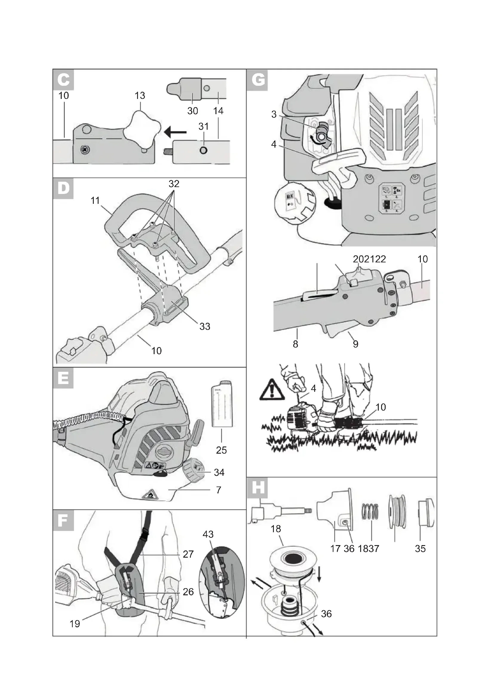
Fitting the Two-Part Tube

-
Remove the protective transport cap (30) from the bottom shaft tube (14).
-
Loosen the tube fixing screw (13) on the top shaft tube (10).
-
Plug the two shaft tubes into each other so the safety button (31) clicks into the borehole provided for it in the top shaft tube (10).
-
Retighten the tube fixing screws (13) by hand.

Ensure that the bottom shaft tube is sitting firmly and safely before starting the equipment.
5. Dismantling:
Loosen the tube fixing screw (13). Press the safety button (31) and pull the tubes apart.
Fitting the anti-vibration handle

-
Loosen the four screws (32) on the anti-vibration handle (11).
-
Put the anti-vibration handle (11) on the rubberised holder (33) provided for this purpose on the upper shaft tube (10).
-
Tighten the anti-vibration handle (11) with the four screws (32).
Initial Operation

Warning! Before initial operation of the equipment, it must be checked that the condition is safe for operation. If there is any doubt, do not start the equipment.
Observe the following points in particular:
- Check the cutting tools for damage and wear.
- Correct installation of the cutting head
- Easy movement of all switches
- Secure sit of the spark plug connector. If the connector is loose, sparks can be formed and thus ignite any leaking fuel-air mix.
- Ensure the handles are clean in order to be able to guide the equipment safely.
- All safety and protective devices must be properly installed and in place before the equipment can be started.
The cutting head must be able to run freely.
Before starting the equipment, ensure that the cutting head is sitting correctly and that the moving parts are free.

Warning! If there is any doubt, seek help with the operation of this equipment from a specialist in an authorised service centre.
Filling with Fuel

Always ensure good ventilation when handling fuel.
Do not smoke when filling with fuel and keep away from any heat sources. Never fill with fuel when the engine is running.
Open the tank cap carefully, so any excess pressure present can be relieved slowly.
Start the equipment min. 3 m away from the fuel filling location. Risk of fire or explosion in case of non-observance

Use only the fuel mix recommended in the instructions. The fuel mix ages. Therefore, do not use fuel mix that is older than 3 months. In case of non-observation, the engine can be damaged and the guarantee will be invalidated.

The filling volume of the tank is 650ml

Avoid direct skin contact with petrol and the inhalation of petrol fumes. Health hazard!

The equipment is fitted with a two-stroke engine and therefore op
erated exclusively with a mix of petrol and two-stroke engine oil in the ratio 50:1.
Table of fuel mixtures:
| Petrol Two-stroke oil | |
| 1,00 litres | 20 ml |
| 3,00 litres | 60 ml |
| 5,00 litres | 100 ml |
| Mixing | 50 parts of petrol + 1 part of oil |
Use quality unleaded petrol with an octane rating of at least 90.
Optimum performance will be achieved with the use of the two-stroke engine oil supplied, designed specifically for the equipment. If this is not available, use super oil for air-cooled two-stroke engines.

-
Prepare the petrol/oil mixture in a clean canister intended for use with petrol (25).
-
First fill in half of the petrol, then all of the oil, then shake the canister. Fill in the rest of the petrol and shake the canister again.
- Remove the filler cap (34) and fill the fuel mixture into the petrol tank (7). Wipe spilled fuel from around the filler opening and replace the filler cap.
Putting on the shoulder strap

Always wear a shoulder strap when working with the equipment. Always switch off the equipment before loosening the shoulder strap. Risk of accidents.

The carrying strap is equipped with a quick-release device. Pulling the red lug (F 43) releases the device quickly from the carrying strap in a dangerous situation.

-
Put on the shoulder strap (27) across your chest.
-
Adjust the strap so the spring clip is around 10cm below the hip.
- Fix the spring clip onto the lifting ring (19) on the shaft tube of the equipment.

Unhook the equipment before starting the engine and fix it to the shoulder strap with the engine running.

Place the protective body (26) on your hip between your body and the device.
Starting the Engine

Start the engine at least three metres from the filling location

Place the appliance on a solid and even surface. Check that the blade is not touching any objects or the ground.

Cold start:
- Make sure that the protective cap on the thread cutter (A 16) is removed.
- Place the device on a firm level surface. Make sure that the cutting tool does not touch either other objects or the ground.
- Turn the choke lever (3) in the direction of the arrow.
-
Press the fuel pump (primer) (A 5) 6 times.
-
Set the On/Off switch (20) to STARTI.
-
Hold the device firmly with one hand by the upper shaft tube (10). With the other hand, pull the starter cable on the starter handle (4) quickly several times in succession until the engine starts.
The device is now idling.
Caution! Do not pull the starter cable out too far - Danger of breakage!
-
Let the engine warm up for about 10 seconds.
-
To mow, keep the throttle lock (22) pressed down and operate the throttle (9). When the throttle is operated, the choke lever (3) automatically jumps into the warm start position.
-
To switch off the engine, move the on/off switch (20) to STOP 0.
Warm start:

During a warm start with the gas locking button, the thread spool rotates after the start. Keep away from the spool. There is a danger of injury!
-
Leave the choke lever (3) in its present position.
-
For half-throttle locking, press the throttle lock (22), throttle (9) and the gas locking button (21) on the handle (8) at the same time. Now release the throttle lock (22) and the throttle (9). The half throttle lock snaps into place.
-
Hold the device firmly with one hand by the upper shaft tube
(10). With the other hand, pull the starter cable on the starter handle (4) quickly several times in succession until the engine starts.
Caution! Do not pull the starter cable out too far - Danger of breakage!
The device is now running with a half-throttle lock.
To switch off the engine, move the on/off switch (20) to STOP.
4.

If the engine has not started after two attempts, try a warm start without the choke in the warm start position. If this is not successful, follow the instructions in the "Troubleshooting" section.

During a warm start, the scythe jumps to the idle position only after the throttle lever has been actuated for the first time.
Operation
Working Notes
-
When cutting, observe the country-specific / local regulations.
-
Do not cut during commonly applicable quiet periods.
-
Solid objects such as stones, metal pieces or similar must be removed. These can be thrown out and therefore result in personal or property damage.
-
When cutting in high bushes or hedges, the working height should be at least 15cm . This prevents the risk to animals, e.g. hedgehogs.
Always hold the equipment firmly and securely with both hands.
- Cut only grass and weeds. Be aware of roots or tree stumps - risk of tripping.
E O
Work considerably and endanger nobody when cutting. Work quietly and carefully.
Work only in adequate visibility and lighting conditions.
- Keep an eye on the cutting head.
- Never cut above shoulder height.
- Never replace the plastic cord with a steel wire - risk of injury and damage.
- Do not work on a ladder.
Work only on firm and stable bases.
- Avoid an abnormal body posture. Ensure that your footing is secure and keep your balance at all times.
- Change your working position at regular intervals in order to prevent becoming tired on one side of your body.
- If the spool become jammed, turn the device off immediately, remove the spark plug connector and then remove the cause of the blockage.
Cutting grass
- On small grass areas, hold the equipment at an angle of approx. 30^ and turn evenly to the right and left with a semi-circular movement.
The best results are obtained with maximum grass length of 15cm If the grass is longer, mowing several times is recommended. - To cut around trees, fence posts or other obstacles, go slowly around the obstacle with the equipment and cut with the thread tips.
- Avoid contact with solid obstacles (stones, walls, board fences etc) otherwise the thread will quickly wear out. Use the edge of the protective cover to keep the equipment at the correct distance
Caution! Do not place the cutting head on the ground during operation!
Extending the cutting thread
The equipment comes with a double-thread tap mechanism, i.e. both threads extend if the cutting head is tapped on the ground.
- Hold the equipment in operation over a grassy area and lightly tap the cutting head a few times on the ground. This extends the thread.
- The thread cutter included in the protective cover (15) cuts the thread to the desired length.
If the thread ends no longer extend:
- Switch off the equipment.
- Press the reel insert until it stops and give a strong pull on the thread end.
If no thread ends are visible:
- Replace the thread reel (see chapter on "Changing the Reel").
Caution! Thread remnants may be thrown out and cause injuries.
If the Equipment Vibrates
Clean the equipment, remove any grass remnants present on the cutting head and in the protective cover.
Care and Maintenance
The maintenance and cleaning work must always be carried out with the engine switched off and the spark plug connector removed (A 2).
Have any work not described in these instructions carried out by our Grizzly service centre.
Never use metallic threads or saw blades. The use of such non-original parts can cause personal injury and irreparable damage to the equipment and will result in immediate invalidation of the guarantee.
Cleaning the Equipment
- Clean the cutting device and protective cover of grass and earth after each cutting procedure.
Always keep the handles clean and free of grass. - Clean the equipment with a soft brush or a damp cloth.

Protect the equipment from damage!
The equipment is to be neither sprayed with water nor placed in water. Do not use detergents or solvents. These could cause irreparable damage to the equipment.
Changing the Reel

- Switch off the engine.
Place the equipment on the ground and ensure that no fuel leaks and that the equipment is safely supported.
Hold the spool case tightly and unscrew the fixing screw (35) anticlockwise. Take off reel capsule (17) with the thread reel (18).
- Place the new reel (18) in the reel capsule (17) and push both ends of the thread through the thread outlet eye (36). Ensure that the spring (37) is in the correct position.
- Push the thread reel (18) into the reel capsule (17) and retighten the fixing screw (35) clockwise
- Pull on both ends of the thread to release the threads from the grooves.
- Trim the thread cord to approx. 13 cm in order to strain the engine less in the start and warm-up phase.

The spare parts which are to be ordered can be found in the "Spare parts/accessories" section
Cleaning the Air Filter

Never operate the equipment without the air filter otherwise dust and dirt enter the engine and result in damage to the machine. Keep the air filter clean.

-
Switch off the engine.
-
Undo the screw (38) on the air filter cover (6) and take off the air filter cover (6) from the air filter housing (39).
- Remove the air filter (40) from the air filter housing (39).
- Clean the filter (40) with soap and water and allow it to dry in the air Never use petrol for cleaning!
- Reinstall the filter (40) and the air filter cover (6) in reverse order.
i Replace the air filter (40) if it is worn, damaged or heavily soiled (see "Spare parts/Accessories").
Changing / Adjusting the Spark Plug
Worn spark plugs or a spark gap that is too great will result in a power reduction of the engine.
-
Switch off the equipment.
-
Take the spark plug connector (2) off of the spark plug (41).
-
Screw out the spark plug (41) anticlockwise using the enclosed maintenance key (see A 23).
-
Check the spark gap with the aid of a feeler gauge (available from specialist retailers). The electrode gap must be 0.6 - 0.7 mm.
-
If necessary, adjust the gap by carefully bending the spark plug (41) earth electrode.
-
Clean the spark plug (41) with a wire brush.
-
Reinsert the cleaned and adjusted spark plug (41) or replace a damaged spark plug (41) with a new spark plug (e.g. "TORCH L8RTC" spark plug).
-
Reattach the spark plug connector (2).
Sharpening the Thread Cutter
Do not use the equipment without a thread cutter or with a defective thread cutter. There is a risk of injury! If the thread cutter blade is damaged, contact our service centre.
Wear protective gloves to avoid cutting injuries.
-
Switch off the equipment.
-
Unscrew the thread cutter (16) from the protective cover (15).
-
Fix the thread cutter (16) in a vice and sharpen the blade with a flat file. File carefully and only ever in one direction.
-
Screw the thread cutter (16) aga-ing on the protective cover (15).
The spare parts which are to be ordered can be found in the "Spare parts/accessories" section
Changing the Fuel Filter
Never operate the equipment without a fuel filter. Change the fuel filter regularly.
-
Remove the filler cap (34).
-
Drain the fuel tank (7) into an appropriate container.
-
Pull the fuel filter (42) out of the tank with a hook and turn to pull it off.
-
Replace the fuel filter and place the removed suction head back in the tank.
-
Close the fuel tank (7) again with the tank cap (34).
The spare parts which are to be ordered can be found in the "Spare parts/accessories" section
Winding up the spool
As an alternative to a new thread spool, you can purchase a 2 mm or 1.8 mm-thick, 5 m-long nylon thread in specialist shops and wind this yourself on the thread spool.

-
Fold the thread in the middle and place the middle of the thread in the notch (45) of the spools (18). Wind up the two ends in the direction of the arrow which is shown on the underside of the spool.
-
Then trap the end of each thread in one of the grooves (46) on the spool (18).
For threads which are 2mm thick, select the grooves which are marked with the number 2, and for threads which are 1.8 mm thick, select the grooves marked 1.8.

Pull the threads tight and ensure that they are parallel in the two thread channels. Furthermore, the thread spool must not be filled with more than 2.5m of thread in each channel, as otherwise the automatic thread mechanism will not function correctly.
Adjusting the Carburettor
The carburettor is preset in the factory for optimal performance. If subsequent adjustments are required, have them carried out by a specialist workshop.
Removing blockages

Switch the device off and remove the spark plug connector before you work on the cutting unit.

Wear protective gloves in order to avoid cutting yourself.
Checking the coupling

Place the device on a firm level surface. Make sure that the cutting tool does not touch either other objects or the ground.
Before each use, check that the coupling is working correctly when idling.
Start the device (see "Starting the engine") and carry out a visual check at a sufficiently safe distance to verify that the thread spool is not turning when the device is idling.
Maintenance Intervals
Regularly carry out the maintenance work listed in the "maintenance intervals" table. Regular maintenance prolongs the life of the equipment. It also gives optimum cutting performance and avoids accidents.
Table "Maintenance Intervals"
| Machine Part Action | Before Each Use | Operating Hours | ||
| 10 20 | ||||
| Screws, nuts, bolts Check, tighten | ✓ | |||
| Air filter Clean or replace | ✓ | |||
| Fuel filter Replace | ✓ | |||
| Spark plug Clean/adjust/replace | ✓ | |||
| Fuel hoses | Check, replace if necessary | ✓ | ||
| Complete machine | Check, clean if necessary | ✓ | ||
| Operating handle | Check for function | ✓ | ||
| Cutting head | Check correct installation | ✓ | ||
| Coupling | Check that the device is sta-tionary when idling | ✓ | ||
Storage
General Storage Instructions
- Clean the equipment and accessories carefully before storage.
- Keep the equipment in a dry and dust-proof place out of reach of children.
- Do not wrap the equipment in plastic bags, as damp and mould may form.
- Do not store the equipment on the protective cover; ideally hang it from the top handle.
Storage During Working Breaks

Non-observation of the storage instructions can cause starting problems or permanent damage as a result of fuel residues in the carburettor.
In case of working breaks of less than 3 months:
- Drain the fuel tank (7) in a well-ventilated place.
- Start the engine and allow it to tick over until the engine stops and the carburettor is free of fuel.
- Allow the engine to cool (approx. 5 minutes).
In case of working breaks of more than 3 months:
- Loosen the spark plug (J 41) with a spark plug wrench (A 23) (see "Changing/Adjusting the Spark Plug").
- Pour a teaspoon of pure 2-stroke oil into the combustion chamber and pull the starter cable slowly several times to distribute the oil inside the engine.
- Reinsert the spark plug (J 41).
Transport
- When it is being transported, the device must be switched off and the spark plug connector (A 2) removed. Do not transport the device when it is idling.
- Carry the device by the multi-function and anti-vibration handle (A 8+11) in order to avoid coming into contact with dangerous parts when transporting it (e.g. hot engine, cutting unit).
- Maintain a safe distance from other people when transporting the device.
- Do not transport the unit upside down, as otherwise fuel might leak out.
Disposal / Environmental Protection
Do not allow used oil and petrol residues into the sewer system or drains.
Dispose of used oil and petrol residues in an environmentally friendly way - take them to a disposal point.
Take the equipment, accessories and packaging for environmentally friendly recycling.
Machinery does not belong in domestic waste.
Drain the petrol tank carefully and take your equipment to a recycling point. The plastic and metal components used can be separated by type and therefore recycled. We will dispose of the defective equipment you send in, free of charge. Ask your Service-Center about this.
Spare Parts/Accessories
Spare parts and accessories can be obtained at www.grizzly-service.eu
If you do not have internet access, please contact the Service Centre via telephone (see "Service-Center" Page 24). Please have the order number mentioned below ready.
Position Position Description Order No.
instruction exploded
manual drawing
| 15 | 37-40,43,44 | Protective cover set | 13602025 |
| 18 | 52,54 | Thread spool | 13602029 |
| 17 | 51-55 | Spool head | 13602027 |
| 37 | 53 | Spring for thread spool | 13602028 |
| 16 | 41,42 | Thread cutter | 13602026 |
| 14 | 33-36,47-50 | Lower tube - complete | 13602024 |
| 27-32 | Coupling sleeve | 13602023 | |
| 11+12 | 23,25,26 | Handle+leg protection | 13602022 |
| 27 | 13 | Shoulder strap+hip protection | 13602021 |
| 42 | 80 | Petrol filter | 13602043 |
| 77-79 | Petrol hoses | 13602042 | |
| 34 | 69-74 | Tank cover | 13602040 |
| 40 | 22 | Air filter | 13602034 |
| 38 | 24 | Air filter screw | 13602035 |
| 41 | 28 | Spark plug | 13602036 |
Alternatively, you can use the AutoCut C5-2 thread spool made by Stihl as a spare part. In specialist shops you can also purchase a 2 mm or 1.8 mm-thick, 5 m-long nylon thread and wind this yourself on the thread spool (see the section on "Winding up the spool").
Guarantee
Dear Customer,
This equipment is provided with a 3-year guarantee from the date of purchase.
In case of defects, you have statutory rights against the seller of the product. These statutory rights are not restricted by our guarantee presented below.
Terms of Guarantee
The term of the guarantee begins on the date of purchase. Please retain the original receipt. This document is required as proof of purchase.
If a material or manufacturing defect occurs within three years of the date of purchase of this product, we will repair or replace - at our choice - the product for you free of charge. This guarantee requires the defective equipment and proof of purchase to be presented within the three-year period with a brief written description of what constitutes the defect and when it occurred.
If the defect is covered by our guarantee, you will receive either the repaired product or a new product. No new guarantee period begins on repair or replacement of the product.
Guarantee Period and Statutory Claims for Defects
The guarantee period is not extended by the guarantee service. This also applies for replaced or repaired parts. Any damages and defects already present at the time of purchase must be reported immediately after unpacking. Repairs arising after expiry of the guarantee period are chargeable.
Guarantee Cover
The equipment has been carefully produced in accordance with strict quality guidelines and conscientiously checked prior to delivery.
The guarantee applies for all material and manufacturing defects. This guarantee does not extend to cover product parts that are subject to normal wear and may therefore be considered as wearing parts (e.g. spool, cutting thread, thread cutter, air filter and spark plug) or to cover damage to breakable parts (e.g. switches).
This guarantee shall be invalid if the product has been damaged, used incorrectly or not maintained. Precise adherence to all of the instructions specified in the operating manual is required for proper use of the product. Intended uses and actions against which the operating manual advises or warns must be categorically avoided.
The product is designed only for private and not commercial use. The guarantee will be invalidated in case of misuse or improper handling, use of force, or interventions not undertaken by our authorised service branch.
Processing in Case of Guarantee
To ensure quick handling of you issue, please follow the following directions:
-
Please have the receipt and identification number (IAN 280454) ready as proof of purchase for all enquiries.
-
Please find the item number on the rating plate.
-
Should functional errors or other defects occur, please initially contact the service department specified below by telephone or by e-mail. You will then receive further information on the processing of your complaint.
E O
- After consultation with our customer service, a product recorded as defective can be sent postage paid to the service address communicated to you, with the proof of purchase (receipt) and specification of what constitutes the defect and when it occurred. In order to avoid acceptance problems and additional costs, please be sure to use only the address communicated to you. Ensure that the consignment is not sent carriage forward or by bulky goods, express or other special freight. Please send the equipment inc. all accessories supplied at the time of purchase and ensure adequate, safe transport packaging.
Repair Service
For a charge, repairs not covered by the guarantee can be carried out by our service branch, which will be happy to issue a cost estimate for you.
We can handle only equipment that has been sent with adequate packaging and postage.
Attention: Please send your equipment to our service branch in clean condition and with an indication of the defect.
Equipment sent carriage forward or by bulky goods, express or other special freight will not be accepted.
We will dispose of your defective devices free of charge when you send them to us.
Service-Center
Service Great Britain
Tel.: 0871 5000 720
(£0.10/Min.)
E-Mail: grizzly@lidl.co.uk
IAN 280454
E Service Ireland Service Northern Ireland
Tel.: 1890 930 034
(0,08 EUR/Min., (peak))
(0,06 EUR/Min., (off peak))
E-Mail: grizzlyy@lidl.ie
IAN 280454
Importer
Please note that the following address is not a service address. Please initially contact the service centre specified above.
| Problem | Possible cause Corrective action | |
| Engine does not start | Tank empty Fill with fuel | |
| Incorrect starting sequence | Follow the instructions in this manual on starting the machine | |
| Engine "flooded" | Remove some gas, start several times; remove, clean and dry the spark plug if necessary | |
| Sooted spark plugs, incorrect spark gap | Clean, adjust or replace the spark plugs | |
| Spark connection, ignition cable damaged | Replace | |
| Carburettor jets dirty, incorrectly adjusted carburettor mix | Have the carburettor cleaned and adjusted by a specialist workshop | |
| Blocked fuel filter Replace or clean the fuel filter | ||
| Engine ticks over too quickly | Engine cold Warm up slowly | |
| Engine does not give top performance | Sooted spark plugs, incorrect spark gap | Clean, adjust or replace the spark plugs |
| Dirty air filter Clean or replace the air filter | ||
| Carburettor jets dirty, incorrectly adjusted carburettor mix | Have the carburettor cleaned and adjusted by a specialist workshop | |
| Incorrect fuel mix Fill up according to | the instructions | |
| Sealing ring in crank case leaking | Have the fault corrected by a specialist workshop | |
| Cylinder, piston rings worn | ||
| Incorrect ignition | ||
| Excessive formation of exhaust/ smoke | Incorrectly adjusted carburettor mix | Have the carburettor cleaned and adjusted by a specialist workshop |
| Incorrect fuel mix Fill up according to | the instructions | |
Table des matieres
Introduction 26
M 45 Encoche Bobine 46 Rainure Bobine
Chere cliente, cher client,