HmIPMIOB - Smart Home Homematic IP - Free user manual and instructions
Find the device manual for free HmIPMIOB Homematic IP in PDF.
| Product Type | Central control unit (Multi IO Box) for Homematic IP Smart Home system |
| Brand | Homematic IP |
| Model | HmIPMIOB |
| Dimensions (W x H x D) | 199 x 156 x 34 mm |
| Weight | 365 g |
| Power Supply | 230 V / 50 Hz, current consumption 30 mA max, standby power 250 mW |
| Main Functions | Switching of recirculation pumps, boilers, circulation pumps; temperature control; heating/cooling mode; inputs for humidity and temperature limiter; 0-10 V output for ventilation (with CCU3) |
| Max. Switching Power (Output 1) | 3680 W, ≥ 0.95 (potential-free) |
| Max. Switching Power (Output 2) | 1840 W, ≥ 0.95 (potential-free) |
| Relay Type | 1-pole changeover contact, μ-contact; 1-pole normally open contact, μ-contact |
| Mechanical Cycles | 10000 |
| Glow Wire Test Temperature | 850 °C |
| Ball Pressure Test Temperature | 125 °C |
| Protection | IP20, protection class II (double insulation) |
| Ambient Temperature | 0 to 50 °C |
| Radio Frequency Band | 868.0-868.6 MHz; 869.4-869.65 MHz |
| Max. Radio Transmit Power | 10 dBm |
| Radio Range in Free Field | 380 m |
| Duty Cycle | < 1 % per h (general) / < 10 % per h (max) |
| Maintenance and Cleaning | Soft, dry, lint-free cloth; no solvent-based products |
| Safety | Installation by qualified electrician; comply with VDE 0100 standards; do not open the device |
| Spare Parts and Repairability | No user-serviceable parts; repair by professional; optional DIN rail adapter (HmIP-DRA) available |
| General Information | Homematic IP Smart Home system; Homematic IP radio protocol; configuration via smartphone app; declaration of conformity available at www.homematic-ip.com |
Frequently Asked Questions - HmIPMIOB Homematic IP
User questions about HmIPMIOB Homematic IP
0 question about this device. Answer the ones you know or ask your own.
Ask a new question about this device
Download the instructions for your Smart Home in PDF format for free! Find your manual HmIPMIOB - Homematic IP and take your electronic device back in hand. On this page are published all the documents necessary for the use of your device. HmIPMIOB by Homematic IP.
USER MANUAL HmIPMIOB Homematic IP
Installation and operating manual

1 Package contents. 20
2 Information about this manual. 20
3 Hazard information 20
4 Function and device overview 21
5 General system information 22
6 Installation 22
7 Start-up 23
7.1 Installation instructions 23
7.2 Installation 24
7.3 Connections 25
7.3.1 Boiler connection 25
7.3.2 Air dehumidifier connection 25
7.3.3 Change over pilot supply 25
7.3.4 Pump connection 25
7.3.5 Humidity sensor connection 25
7.3.6 External changeover signal connection 26
7.3.7 External timer connection 26
7.3.8 Temperature limiter connection 26
7.4 Pairing 26
7.4.1 Pairing with the Homematic IP Floor Heating Actuator 26
7.4.2 Pairing with the Homematic IP Access Point 27
8 Troubleshooting 28
8.1 Command not confirmed 28
8.2 Duty cycle 28
8.3 Error codes and flashing sequences 29
9 Restoring factory settings 30
10 Maintenance and cleaning 30
11 General information about radio operation 30
12 Disposal. 31
13 Technical specifications 32
Documentation © 2016 eQ-3 AG, Germany
All rights reserved. Translation from the original version in German. This manual may not be reproduced in any format, either in whole or in part, nor may it be duplicated or edited by electronic, mechanical or chemical means, without the written consent of the publisher.
Typographical and printing errors cannot be excluded. However, the information contained in this manual is reviewed on a regular basis, and any necessary corrections will be implemented in the next edition. We accept no liability for technical or typographical errors or the consequences thereof.
All trademarks and industrial property rights are acknowledged.
Changes in line with technical progress may be made without prior notice.
150305 (web) | Version 1.5 (07/2024)
1 Package contents
1x Multi IO Box
4x Screws, 4.0 × 40 ~mm
4x Wall plugs, 6 mm
1x Operating manual
2 Information about this manual
Please read this manual carefully before operating your Homematic IP components. Keep the manual so you can refer to it at a later date if you need to. If you hand over the device to other persons for use, please hand over this manual as well.
Symbols used:

Important! This indicates a hazard.

Please note: This section contains important additional information!
3 Hazard information

Do not open the device. It does not contain any parts that need to be maintained by the user. In the event of an error, please have the device checked by an expert.

For safety and licensing reasons (CE), unauthorised changes and/or modifications to the device are not permitted.

The device may only be used for fixed installations. The device must be securely attached within a fixed installation.

The device may only be operated in dry and dust-free environment and must be protected from the effects of moisture, vibrations, solar or other methods of heat radiation, cold and mechanical loads.

The device is not a toy: do not allow children to play with it. Do not leave packaging material lying around. Plastic films/bags, pieces of polystyrene, etc., can be dangerous in the hands of a child.

We accept no liability for damage to property or personal injury caused by improper use or the failure to observe the hazard warnings. In such cases, all warranty claims are void. We accept no liability for any consequential damage.

The actuator is part of the building installation. Observe the relevant national standards and directives during planning and set-up. Only qualified electricians (to VDE 0100) are permitted to carry out work on the 230V mains. The applicable accident prevention regulations must be observed while such work is being carried out. To avoid electric shocks from the device, please disconnect the mains voltage (trip the miniature circuit-breaker). Non-compliance with the installation instructions can cause fire or introduce other hazards.

When connecting to the device terminals, observe the cables and cable cross-sections permitted for this purpose.

Please take the technical data (in particular the maximum permissible effective installed load of the device and the type of load to be connected) into account before connecting a load! All load data relates to ohmic loads. Do not exceed the capacity specified for the device.

The device has not been designed to support safety disconnection.

Exceeding this capacity could lead to the destruction of the device, fires or electric shocks.

Before the actuator is connected, remove the fuse from the fuse box.

Observe the installation instructions for installation in distribution systems (DIN VDE 0100-410).

The control voltage of the 0 to 10 V output is electrically isolated from the mains potential but is not at safety extra-low voltage (SELV). This must be observed during cable routing, installation and connection.

The device is only suitable for use in residential environments.

Using the device for any purpose other than that described in this operating manual does not fall within the scope of intended use and will invalidate any warranty or liability.
4 Function and device overview
The Homematic IP Multi IO Box is the central control unit for controlling heat pumps, boilers and circulation pumps. The device allows comfortable and demand-based regulation of the room and water temperature according to your personal needs via smartphone app.
With the Multi IO Box, the heating system can be switched from heating to cooling and thus offers lowering of the room temperature using the floor heating.
Thanks to the input for a humidity and temperature limiter, mould formation caused by condensation water on the cables or overheating of the heating system can be reliably avoided. You can flexibly mount the device using the supplied screws or the Homematic IP DIN-Rail Adapter HmIP-DRA (available as an option).
Device overview:
(A) System button (pairing button and LED)
(B) cover
(C) PE (protective conductor) connect- ing terminals
(D) connecting terminal for L (phase conductor)
(E) connecting cable for N (neutral conductor)
(F) connecting terminal 4 (e.g. for connecting a boiler)
(G) connecting terminal 5 (changeable terminal e.g. for connecting circulating pumps)
(H) LEDs for connection display
(I) connecting terminal IN1/IN2 (heating, cooling or eco operation, temperature or humidity limiter)
(J) Connecting terminals for AOUT (0 - 10 V output, e.g. for ventilation control, function available in connection with a Central Control Unit CCU3)
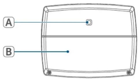
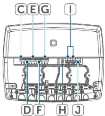
Figure 1
5 General system information
This device is part of the Homematic IP Smart Home system and communicates via the Homematic IP wireless protocol. All devices in the Homematic IP system can be configured easily and individually with a smartphone using the Homematic IP app. The available functions provided by the system in combination with other components are described in the Homematic IP User Guide. All current technical documents and updates can be found at www.homematic-ip.com.
6 Installation
You can flexibly mount the Multi IO Box on walls using the supplied screws and plugs.

Alternatively, you can mount the Multi IO Box with the Homematic IP DIN-Rail Adapter HmIP-DRA (available as an option). For further information, please refer to the user manual of the DIN-rail adapter.
For mounting the Multi IO Box using screws, please proceed as follows:
- Please select a suitable mounting location close to your heating system.

Make sure that no electricity or similar lines run in the wall at this location!
- Use a pen to mark the positions of the four bore holes on the wall.
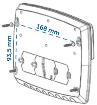
Figure 2
- Use an appropriate drill to make the 6mm holes as illustrated.
- Use the screws and plugs supplied to fasten the Multi IO Box (see fig. 2).
- Use an appropriate drill to make the 6mm holes as illustrated.
- Fasten the screws and plugs supplied to mount the floor heating controller.
7 Start-up
7.1 Installation instructions

Please read this entire section before starting the pairing procedure.

Please note! Only to be installed by persons with the relevant electro-technical knowledge and experience!*
Incorrect installation can endanger
- your own life,
and the lives of other users of the electrical system.
Incorrect installation also means that you are running the risk of serious
damage to property, e.g. from fire. You risk personal liability for personal injury and property damage.
Consult an electrician!
*Specialist knowledge required for installation:
The following specialist knowledge is particularly important during installation:
- The "5 safety rules" to be used: Disconnect from the mains; Safeguard against switching on again; Check that system is deenergised; Earth and short circuit; Cover or cordon off neighbouring live parts;
- Select suitable tool, measuring equipment and, if necessary, personal safety equipment;
- Evaluation of measuring results;
- Selection of electrical installation material for safeguarding shut-off conditions;
IP protection types; - Installation of electrical installation material;
- Type of supply network (TN system, IT system, TT system) and the resulting connecting conditions (classic zero balancing, protective earthing, required additional measures etc.).

To install the Multi IO Box in a power distribution panel, it must be mounted in accordance with VDE 0603, DIN 43871 (low-voltage sub-distribution board), DIN 18015-x. In this case, installation must take place on a mounting rail (DIN rail) according to
EN 50022. Installation and wiring must be performed according to VDE 0100 (VDE 0100-410, VDE 0100-510 etc.). Please consider the technical connection requirements (TCRs) of your energy supplier.

The circuit to which the device and the load will be connected must be protected by a circuit breaker in accordance with EN 60898-1 (tripping characteristic B or C, max. 16 A rated current, min. 6 kA breaking capacity, energy limitation class 3). Installation regulations according to VDE 0100 and HD382 or 60364 must be observed. The circuit breaker must be easily accessible to the user and marked as the disconnecting device for the actuator.

Please observe the hazard information in section (see 3 Hazard information" on page 20) during installation.
Permitted cable cross sections for connecting to the Multi IO Box:
| Rigid cable Flexible | cable with/without fer- rule |
| 0.75 - 2.5 mm² 0.75 | - 2.5 mm² |
Permitted cable diameter for cable bushings are:
| Terminals 1 - 5 Terminal 6 |
| 8 - 11 mm 5 - 8 mm |
7.2 Installation

For comfortable installation you can pull the cable through the cable inlets after having removed the breakout openings.
To install the Multi IO Box, please proceed as follows:
- Open the cover (B). To do this, unscrew both lower screws with an appropriate screwdriver and then remove the cover.
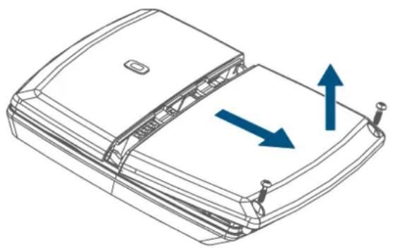
Figure 3
- Connect the protective conductor to connecting terminal PE (C).
- Connect the phase conductor to connecting terminal L (D).
- Connect the neutral conductor to connecting terminal N (E).
- Connect e.g. the boiler to connecting terminal 4 (F) or a circulation pump to connecting terminal 5 (G).
-
You can expand the installation depending on the installation conditions or according to your personal needs (e.g. for ventilation control). For further information regarding the connection options please refer to section (see "7.3 Connections" on page 25).
-
Close the cover again. To do this, push the latches of the cover into the openings provided and fasten the screws.
7.3 Connections
7.3.1 Boiler connection
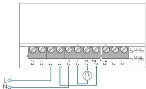
Figure 4
7.3.2 Air dehumidifier connection

This type of connection can be realised only in conjunction with a Homematic IP Access Point or Homematic Central Control Unit CCU3.
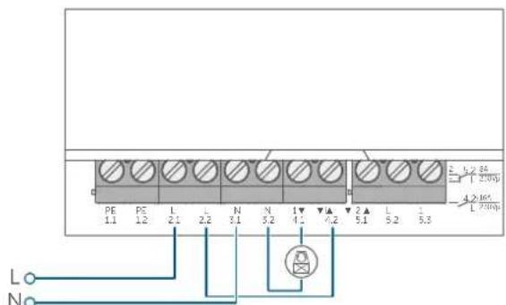
Figure 5
7.3.3 Change over pilot supply

Each heating zone will be shown on the display according to the valve position after a successful adjustment run.
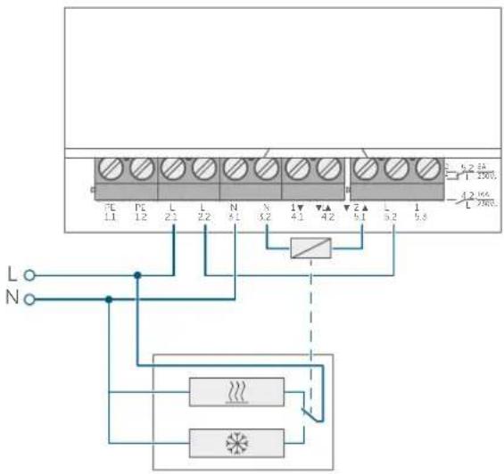
Figure 6
7.3.4 Pump connection
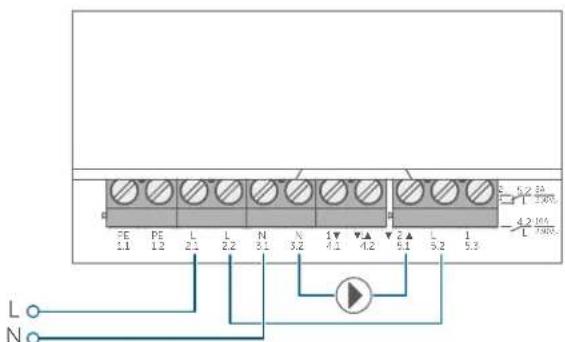
Figure 7
7.3.5 Humidity sensor connection
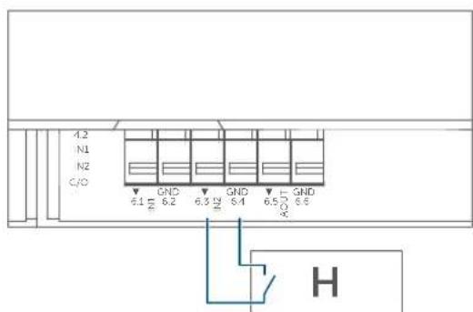
Figure 8
7.3.6 External changeover signal connection
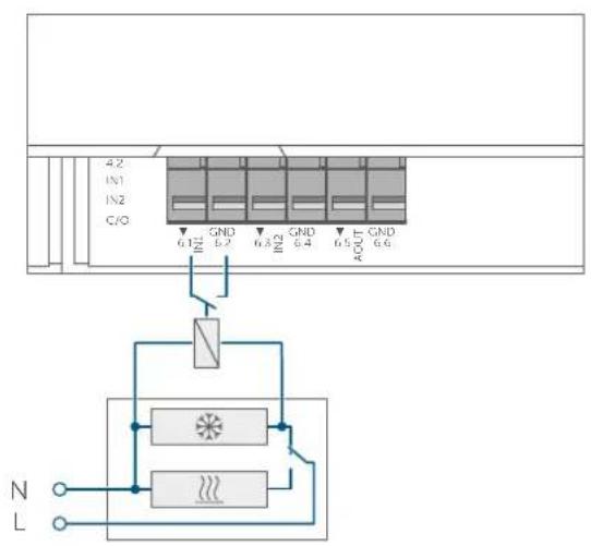
Figure 9
7.3.7 External timer connection

This type of connection can be realised only in conjunction with a Homematic IP Access Point or Homematic Central Control Unit CCU3.
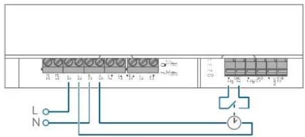
Figure 10
7.3.8 Temperature limiter connection

This type of connection can be realised only in conjunction with a Homematic IP Access Point or Homematic Central Control Unit CCU3.
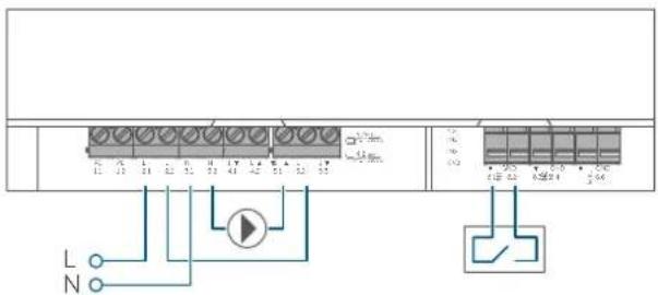
Figure 11
7.4 Pairing

Please read this entire section before starting the pairing procedure.
To integrate the Multi IO Box into your system and enable it to communicate with other devices, you must connect it first.
You can either pair the Multi IO Box directly with the Homematic IP Floor Heating Actuator or pair it with the Homematic IP Access Point. If you add the device to the Access Point, configuration is done via the Homematic IP app.
7.4.1 Pairing with the Homematic IP Floor Heating Actuator

Please make sure you maintain a distance of at least 50~cm between the devices during pairing.

You can cancel the pairing procedure by briefly pressing the system button (A) again. This will be indicated by the device LED lighting up red.

If you would like to integrate the Multi IO Box into an existing system, you first have to activate the pairing mode of the floor heating
actuator and afterwards the pairing mode of the Multi IO Box.
If you want to pair the Muli IO Box with a Homematic IP Floor Heating Actuator, the pairing mode of both devices has to be activated first. To do this, proceed as follows:
- Press and hold down the system button (A) of the Multi IO Box for at least 4 seconds to activate the pairing mode. The device LED flashes orange.
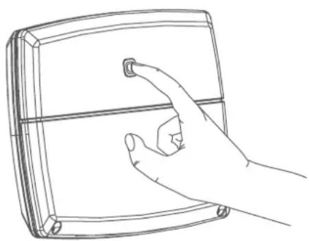
Figure 12
- Activate the pairing mode of your floor heating actuator. Briefly press the select button until the LEDs of all channels light up green.
- Press and hold the system button on the floor heating actuator for 4 seconds until the LED starts to flash orange fast.
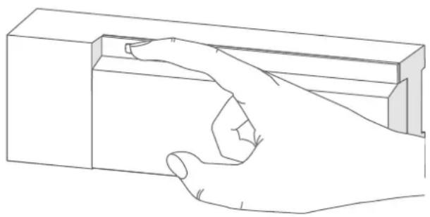
Figure 13
The device LED (A) flashes green to indicate that pairing has been successful. If pairing failed, the device LED (A) lights up red. Please try again.

If no pairing operations are performed, pairing mode is exited automatically after 3 minutes.
7.4.2 Pairing with the Homematic IP Access Point

You can connect the device either to the Homematic IP Access Point or the Central Control Unit CCU3. Further information is available in the Homematic IP User Guide (available to download in the Downloads section at www.homematic-ip.com).

First set up your Homematic IP Access Point using the Homematic IP app so that you can use other Homematic IP devices in the system. For further information, please refer to the Access Point operating manual.
To add the Multi IO Box to the Access Point, please proceed as follows:
- Open the Homematic IP app on your smartphone.
- Select "Add device".
- Briefly press the system button (A) until the LED starts to flash orange slowly ( see figure). The pairing mode is active for 3 minutes.

You can manually start the pairing mode for another 3 minutes by briefly pressing the system button (A) ( see figure).
Your device will automatically appear in the Homematic IP app.
- To confirm, please enter the last four digits of the device number (SGTIN) in your app or scan the QR code of your device. The device number can be found on the sticker supplied or attached to the device.
- Wait until pairing is complete.
If pairing was successful, the LED lights up green. The device is now ready for use.
If the LED lights up red, please try again. - Select the desired solution for your device.
- In the app, give the device a name and allocate it to a room.
8 Troubleshooting
8.1 Command not confirmed
If at least one receiver does not confirm a command, the device LED (A) lights up red at the end of the failed transmission process. The reason for the failed transmission may be radio interference (see "11 General information about radio operation" on page 30). This may be caused by the following:
- Receiver cannot be reached.
- Receiver is unable to execute the command (load failure, mechanical blockage, etc.).
- Receiver is faulty.
8.2 Duty cycle
The duty cycle is a legally regulated limit of the transmission time of devices in the 868 MHz range. The aim of this regulation is to safeguard the operation of all devices working in the 868 MHz range.
In the 868 MHz frequency range we use, the maximum transmission time of any device is 1% of an hour (i.e. 36 seconds in an hour). Devices must cease transmission when they reach the 1% limit until this time restriction comes to an end. Homematic IP devices are designed and produced with 100% conformity to this regulation.
During normal operation, the duty cycle is not usually reached. However, repeated and radio-intensive pairing processes mean that it may be reached in isolated instances during start-up or initial installation of a system. If the duty cycle is exceeded, this is indicated by three slow red flashes of the device LED, and may manifest itself in the device temporarily working incorrectly. The device starts working correctly again after a short period (max. 1 hour).
8.3 Error codes and flashing sequences
| Flashing code Meaning Solution | ||
| Short orange flashes | Radio transmission/attemptsing to transmit/data transmission | Wait until the transmis-sion is completed. |
| 1x long green flash Transmis-sion confirmed | You can continue oper-a-tion. | |
| 1x long red flash | Transmission failed or duty cycle limit reached | Please try again (see „8.1 Command not confirmed" on page 28) or (see „8.2 Duty cycle" on page 28). |
| Short orange flashes (every 10 s) | Pairing mode active (pair-ing with the access point) | Enter the last four digits of the device serial number to confirm (see „7.4 Pair-ing" on page 26). |
| Fast orange flashing | Pairing mode of both de-vices active (pairing) | Wait for confirmation of the device LED (see „8.3 Error codes and flash-ing sequences" on page 29). |
| 1x long red flash | Transmission failed or duty cycle limit is reached | Please try again (see „8.1 Command not confirmed" on page 28) or (see „8.2 Duty cycle" on page 28). |
| 6x long red flashes Device defective | Please see your app for error messages or contact your retailer. | |
| 1x orange and 1x green lit up | Test display | You can continue once the test display has stopped. |
9 Restoring factory settings

The factory settings of the device can be restored. If you do this, you will lose all your settings.
To restore the factory settings of the Multi IO Box, please proceed as follows:
- Press and hold the system button (A) for 4 seconds until the LED (A) starts to quickly flash orange ( see figure).
- Release the system button.
- Press and hold the system button again for 4 seconds, until the LED lights up green.
- Release the system button to finish restoring the factory settings.
The device will perform a restart.
10 Maintenance and cleaning

The product does not require any maintenance. Enlist the help of an expert to carry out any repairs.
Clean the device using a soft, clean, dry and lint-free cloth. dampen the cloth a little with lukewarm water to remove more stubborn marks. Do not use any detergents containing solvents, as they could corrode the plastic housing and label.
11 General information about radio operation
Radio transmission is performed on a non-exclusive transmission path, which means that there is a possibility of interference occurring. Interference can also be caused by switching operations, electrical motors or defective electrical devices.

The transmission range within buildings can differ significantly from that available in open space. Besides the transmitting power and the reception characteristics of the receiver, environmental factors such as humidity in the vicinity play an important role, as do on-site structural/screening conditions.
eQ-3 AG, Maiburger Straße 29, 26789 Leer, Germany hereby declares that the radio equipment type Homematic IP HmIP-MIOB is compliant with Directive 2014/53/EU. The full text of the EU declaration of conformity can be found at www.homematic-ip.com
Disposal
12 Disposal
Instructions for disposal
This symbol means that the device must not be disposed of as house
hold waste, general waste, or in a yellow bin or a yellow bag.
For the protection of health and the environment, you must take the product and all electronic parts included in the scope of delivery to a municipal collection point for old electrical and electronic equipment to ensure their correct disposal. Distributors of electrical and electronic equipment must also take back obsolete equipment free of charge.
By disposing of it separately, you are making a valuable contribution to the reuse, recycling and other methods of recovery of old devices.
Please also remember that you, the end user, are responsible for deleting personal data on any used electrical and electronic equipment before disposing of it.
Information about conformity
The CE mark is a free trademark that is intended exclusively for the authorities and does not imply any assurance of properties.
For technical support, please contact your retailer.
13 Technical specifications
Device short description: HmIP-MIOB
Supply voltage: 230V / 50Hz
Current consumption: 30mA max.
Power consumption in standby: 250mW
Max. switching capacity:
Output 1: 3680 W, cos ≥ 0,95 (floating)
Output 2: 1840 W, cos ≥ 0,95 (floating)
Cable type and cross section: rigid and flexible cable, 0.75 - 2.5mm^2
Kind of load: ohmic load
Method of operation: Type 1.B
switching cycle: 10000
Relay: Changeover contact, 1-pole, contact
NO contact, 1-pole, contact
Withstand voltage: 4000 V
Temperature glow wire test: 850°C
Temperature ball pressure test: 125^
Construction: Independently mounted electronic regulation and control device
Pollution degree: 2
Protection rating: IP20
Protection class:
Ambient temperature: 0 - 50^
Dimensions (W x H x D): 199 x 156 x 34 mm
Weight: 365 g
Radio frequency band: 868.0 - 868.6 MHz
869.4 - 869.65 MHz
Max. radio transmission power: 10 dBm
Receiver category: SRD category 2
Typical range in open space: 380 m
Subject to modifications.
Table des matieres
Dimensioni (L x A x P):
365g
Peso:
868,0-868,6 MHz
Afmetingen (b× h× d)
365g
Gewicht:
868,0-868,6 MHz
Zendfrequentieband:
10 dBm
869,4-869,65 MHz
SRD class 2
Max. zendvermogen:
380 m
Ontvangersklasse:
Free download of the Homematic IPapp!


Download on the
App Store


GET IT ON
Google Play
Bevolmächtigter des Hersteilers: Manufacturer's authorised representative:

eQ-3 AG
Maiburger StraBe 29
26789 Leer / GERMANY
www.eQ-3.de