75264001 - Motion detector BERKER - Free user manual and instructions
Find the device manual for free 75264001 BERKER in PDF.
Frequently Asked Questions - 75264001 BERKER
User questions about 75264001 BERKER
0 question about this device. Answer the ones you know or ask your own.
Ask a new question about this device
Download the instructions for your Motion detector in PDF format for free! Find your manual 75264001 - BERKER and take your electronic device back in hand. On this page are published all the documents necessary for the use of your device. 75264001 by BERKER.
USER MANUAL 75264001 BERKER
text_image
B. Berker instabus® E19Präsenzmelder
natural_image
Circular metallic object with a black ring and a small circular mark at the bottom (no text or symbols)Inhaltsverzeichnis
Systeminformation 3
Gefahrenhinweise 4
text_image
Warning sign with exclamation mark inside a triangleGefahrenhinweise
text_image
Diagram illustrating light emission and heat transfer with labeled symbols for sun, fan, and heating elementsMontage
natural_image
Mechanical assembly diagram showing a component with a curved base and labeled part (①), no readable text or symbols present.natural_image
Diagram showing a curved arrow between two shaded regions with directional arrows, no text or symbols present.Operating Instructions

text_image
B. Berker instabus®Presence detector
natural_image
Circular metallic ring with a black inner ring and a small circular mark at the bottom (no text or symbols)Contents
System information 25
Safety warnings 26
Presence detector principle ...... 27
Function of presence detector 'Standard' 28
Function of presence detector 'Komfort' 28
Description of the modes of operation 29
Fitting 32
Adjustment 34
Adjustment information 36
Field of detection 38
Snap-on mask 40
Technical data 42
Manufacturer's warranty 43
System Information
This unit is a product of the instabus-EIB-System and corresponds to the EIBA Guidelines. Detailed technical knowledge acquired in instabus training courses is a prerequisite for the understanding of the system. The functions of the device are software-dependent. Detailed information on the software and the functions implemented and the software itself are available from the manufacturer's product data bank.
Planning, installation and commissioning of the device are effected with the help of EIBA-certified software

text_image
Warning sign with exclamation mark inside a triangleSafety warnings
Attention: Electrical equipment must be installed and fitted by qualified electricians only.
Non-observance of the installation instructions may damage the device and cause fire or other hazards.
Presence detector principles
A presence detector belongs to the group of passive infra-red detectors (PIR) exactly like movement detectors or detectors for alarm systems.
These devices can be distinguished by their internal structure, signal detection and signal evaluation which make them suitable for different applications:
■After detecting movements, a movement detector switches the light on dependent on brightness and off in dependent of brightness when no movements are detected anymore.
■A movement detector for alarm systems signals a movement (pulse) to a central alarm station independent of brightness. The number of pulses transmitted within a time slot can often be freely selected. The field of detection is limited to narrower angles (90° and in most cases even less).
■A presence detector is designed to switch on the light dependent on brightness when movements are detected and to switch it off when it is no longer needed. This is the case if it is bright enough without artificial lighting or when no one is present anymore.
This means that the 'presence' of a person is detected depending on a preset brightness level.
These PIR detectors differ mainly in the design of the Fresnel lense installed, their adjustment with regard to ambient conditions, the type of fitting and the properties of the movement or brightness signal.
A presence detector is exclusively installed under the ceiling of a room and monitors the room surface below.
It works with a passive infra-red sensor (PIR) and responds to thermal movements triggered by persons, animals or objects.
Function of presence detector 'Standard'
The presence detector 'Standard' is used for the detection of presence (presence detector mode) and for the detection of movements (ceiling detector mode) in rooms.
Both modes of operation offer 2 independently programmable output channels.
The respective mode of operation (ceiling detector or presence detector) is programmed for the presence detector 'Standard' model with the ETS software.
Subsequent switching between the operating modes is not possible. A change of the mode of operation requires reprogramming of the device.

The presence detector 'Standard' can only be used as a stand-alone unit. It is not possible to use several presence detectors 'Standard' in the same room to enlarge the detection range. The detectors would interfere with one another.
Function of presence detector 'Komfort'
The instabus presence detector 'Komfort' can be operated in three different modes:
• ceiling detector mode
- presence detector mode
- signalling mode
The modes are selected when the device is programmed with the ETS software. The device can be programmed so that only one mode is active (mono operation) or that the device can be switched between two preset modes via the instabus EIB (alternative operation, e.g day-time presence mode and night-time signalling mode). Both modes of operation offer two output channels with independent parameter programming.

Depending on the type of application, the presence detector 'Komfort' can be used as individual unit, main unit or extension unit. The operation as main unit and as extension unit permits enlarging the zone of detection. The presence detector 'Komfort' can also be used in combination with flush-mounted automatic switches from BERKER in a master-slave configuration. For brightness-independent activation it is also possible to use a touch sensor as extension unit.
Description of the modes of operation with predefined parameters Ceiling detector mode
In the ceiling detector mode, the device detects movements and transmits the programmed telegram representing the beginning of detection, when the measured brightness is below the preset brightness value.
The device is now operational independent of brightness. If no further movements are detected, the device transmits the programmed telegram representing the end of detection when the preset overall transmit delay has elapsed.
Presence detector mode
In the presence detector mode, the device detects the presence of a person and transmits the programmed telegram representing the beginning of detection, when the measured brightness is below the preset brightness value.
If no presence is detected anymore and if the preset overall transmit delay has elapsed or if the preset brightness value has been exceeded for at least 10 minutes by the double, the presence detector transmits the programmed telegram representing the end of detection.
The functional difference with regard to the ceiling detector mode lies...
a) in the processing of the movement signal
Contrary to the ceiling detector mode, a presence is detected only after several successive movement pulses have been received.
b) in the processing of the brightness signal
The presettable brightness range to be monitored for the brightness threshold value is larger than in the ceiling detector mode.
It is only after twice the value of the preset brightness threshold (switch-off brightness) has been exceeded that the programmed telegram representing the end of detection is transmitted after ca. 10 minutes even if someone is still present.
This switch-off brightness can be changed with a correction factor in the programmed parameters.
c) in the evaluation of combined movement and brightness signals
The light is switched on when a person is present and when, at the same time, the brightness falls below the preset brightness threshold.
The light is switched off when nobody is present or when the ambient brightness without artificial lighting is high enough.
Signalling mode (only in the 'Komfort' version)
In this mode with a signalling function, the device detects movement pulses independent of brightness and counts them with a pulse counter. If – within a fixed time-span (standard value: 10 seconds) – at least the fixed number of pulses (standard value: 4) have passed the counting gate, the programmed telegram representing the beginning of detection will be transmitted.
When no movement pulses are detected anymore, the presence detector transmits the programmed telegram representing the end of detection after the standard transmit delay of 10 seconds has elapsed. In the signalling mode, the presence detector 'Komfort' is always operated as an individual unit.
Further product features:
- Alarm function: When someone tries to remove the device, the detector can be made to transmit a programmed telegram.
- Teach-in function: The switch-on threshold within the brightness range can be changed by means of an instabus EIB telegram.
A more detailed description of the functions is given in the instabus documentation for these products.
text_image
Diagram illustrating light emission, radiation, and heat transfer with labeled symbols and equationsFitting
The presence detector must be installed together with an instabus bus coupler only under the ceiling. The fitting and connection instructions for bus couplers are set out in the technical documentation of this product.
Plug the presence detector on the base without exerting pressure on the lens. The electrical contact is established via the user interface (AST).
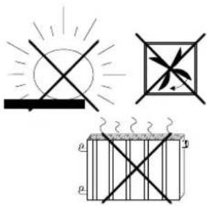
Sources of interference:
Do not install the device in the direct vicinity of heat sources as, for instance, lamps (illustration on the left). Cooling of the lamp might be interpreted by the PIR sensor as a thermal change and trigger another detection cycle. The presence detector must not be installed close to fans, radiators or ventilation ducts either. Draughts (also from open windows) might be detected as movements and cause retriggering of the device.
If necessary, the detecting range must be confined by means of the snap-on mask supplied with the device (see also 'Snap-on mask').
natural_image
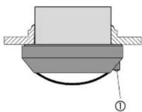
Mechanical assembly diagram showing a component with a curved base and hatched side (no text or symbols)Remember that the detection field is restricted by obstacles such as furniture, columns, etc. Movements behind obstacles cannot be detected.
The brightness sensor (1) should be installed on the side away from the window to avoid the undesired influence of scattered light.
Install the presence detector in a place free from vibrations, since the device may also be triggered by movements of the sensor.
Important: Avoid direct sunlight into the sensor window.
The sensors might be irreparably damaged by the high thermal energy.
text_image
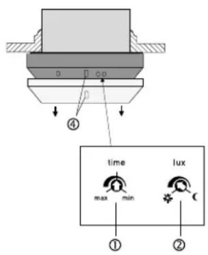
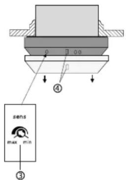
time max min lux ① ②Adjustment
After fitting and programming with the ETS, the range settings defined in the software may be modified with the help of potentiometers provided on the device itself, if this function is enabled in the software.
To adjust brightness, on-time and sensitivity, withdraw first the decorative ring (4) from the presence detector. The potentiometers are then accessible.(see illustration on the left)
(1) On-time: time
The software-defined 'supplementary transmit delay' corresponds to the center position of the potentiometer and can be changed by +/- 50%, e.g.. 120 s +/- 60 s.
(2) Brightness: lux
Fine-tuning of the software-defined twilight threshold. The setting range depends on the mode of operation selected and comprises the full range of twilight values, e.g. 300 - 600 lux.
text_image
④ sens max min ③(3) Sensitivity: sens
Stepless reduction of the maximum reach from 100% down to ca. 20% independent of the software settings.
Put the decorative ring (4) back in place after the adjustment. The nose of the brightness sensor must engage in the opening in the decorative ring (4).

Useful information:
The lower the number of movements expected in the controlled area the longer should be the supplementary transmit delay to prevent premature switching off of the lighting.
Adjustment information
If the software-defined values are not precise enough, they can be adapted within a limited range with the help of the lux and time potentiometers, if this function is enabled in the software. If the necessary readjustment exceeds the predefined range, the parameters must be corrected and the device reprogrammed thereafter.
| Load remains on even with strong external light (e.g. bright sunlight) | |
| Cause | Remedial action |
| Present brightness value too high | Turnlux potentiometer towards ‘Moon’ |
| Load not switched when movement is detected on in spite of insufficient brightness | |
| Cause | Remedial action |
| Present brightness value too low | Turnlux potentiometer towards ‘Sun’ |
| Load switched off although persons are present and lighting is insufficient | |
| Cause | Remedial action |
| Preset time too short | Select longer time with the time potentiometer |
| Detection problem, the surface to be monitored is outside the detection range, furniture or columns in the way | Check the detection range |
| Load switched on without noticeable movements | |
| Cause | Remedial action |
| Sources of interference within detection range | see chapter ‘Fitting’ |
| Load switched off briefly and immediately thereafter on again | |
| Cause | Remedial action |
| After shutoof, the ambient brightness falls below the preset minimum brightness, device switches on again immediately when movement is detected | Turn lux potentiometer by a small amount in the direction of ‘Sun’ |
Additional information on the measurement of brightness values:
The brightness values detected by the presence detector depend on several conditions. The reflexion of light by the surface directly under the presence detector is of decisive importance. Bright surfaces such as white paper on the desktop reflects of course much more light than a dark carpet. It may therefore be necessary to change the setting of a presence detector when the bright desktop below is moved to another place in the room and when there is now a dark carpet under the detector instead.
Field of detection
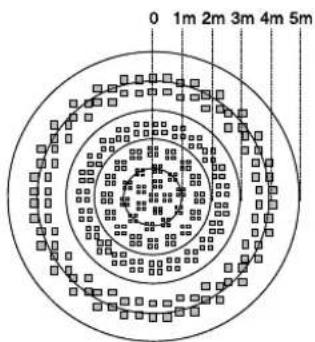
The presence detector has a detection range of 360°.
The PIR sensor system works with 6 detection levels and 80 lenses.
The field is ca. 5 m in diameter at desktop height (ca. 80 cm). The field diameter on the floor is ca. 8 m.
These values are referred to an installation under the ceiling at a height of 2.5 m and tangential, i.e. lateral movement.
Important:
In the event of movements directed straight towards the presence detector, a reduction of the detection range must be expected. In this case, detection in the outer 4m range is not ensured.
If a person approaches the presence detector quickly, there may be the impression of a reduced range.
In this respect, attention must also be paid to possible switch-on delays of the lamps used.
This aspect must be observed especially in such applications where the device is used as a ceiling detector.
A significant increase of the installation height reduces the sensitivity of the device to detect movements.
text_image
0 1m 2m 3m 4m 5mField of detection viewed from above: picture on the left
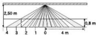
Field of detection viewed from the side: picture on the left
Snap-on mask

To protect the system of lenses,
the device is delivered with the transparent snap-on mask already in place.
To obtain maximum detection range, the mask must be removed.
The snap-on mask supplied can be used to blank out undesired zones of detection or sources of interference (see chapters Fitting, Sources of interference) by limiting the detection field.
Determine the zones which are to be excluded from detection.
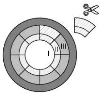
Cut out the mask after removal from the sensor along the marked lines in such a way that the mask blanks the zones determined above.
text_image
Diagram showing a circular segmented structure with labeled zones and a separate curved section with scissors, likely illustrating a mechanical or electrical component.Cutting out the mask changes the diameter of the detection field on the floor as follows:
Zones I to III see illustration on the left.
complete mask.
no cut-out zone I: ∅ ca. 2,20 m
zone II cut out: ∅ ca. 4,00 m
zone II+III cut out: ∅ ca. 6,00 m
without mask: ∅ ca. 8,00 m
The figures are referred to an installation height of ca. 2.50 m.
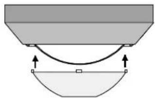
natural_image
Diagram showing a curved arrow between two shaded regions with directional arrows, no text or symbols present.The mask is fastened with a snap on the lens system (picture on the left).
Technical data
Connection: via AST (2 x 5 poles)
Angle of detection: 360°
Nominal field of detection
at desktop level: ∅ approx. 5 m
Nominal field of detection
at floor level: ∅ approx. 8 m
Height of installation for
nominal field of detection: approx. 2,5 m
The nominal field of detection varies with
the height of installation.
Number of lenses /levels of detection:80 / 6
Technical specifications subject to change.
Acceptance of guarantee
We accept the guarantee in accordance with the corresponding legal provisions.
Please return the unit postage paid to our central service department giving a brief description of the fault:
Please forward these instructions to
your customer after installation.
text_image
B. Berker instabus® E13Aanwezigheidsmelder
natural_image
Circular metallic ring with a black inner ring and a small circular mark at the bottom (no text or symbols)Inhoudsopgave
Systeeminformatie...... 47
text_image
Warning sign with exclamation mark inside a triangletext_image
Diagram illustrating light and dust emission, including sun, fan, and heat transfer symbols with labeled pressure indicators.Montage
natural_image
Mechanical assembly diagram showing a component with a curved base and hatched top surface (no text or symbols)natural_image
Diagram showing a curved line between two shaded regions with directional arrows, no text or symbols present.text_image
B. Berker instabus® E13natural_image
Circular metallic object with a black ring and a small circular mark at the bottom (no text or symbols)Table des matières
text_image
Warning sign with exclamation mark inside a triangle, commonly used to indicate caution or hazard.text_image
Diagram illustrating light and dust emission, including sun, fan, and heat transfer symbols with labeled pressure indicators.Montage
natural_image
Mechanical assembly diagram showing a component with a curved base and hatched top surface (no text or symbols)natural_image
Diagram showing a curved line between two shaded regions with directional arrows, no text or symbols present.text_image
B. Berker instabus® E13Presensmelder
natural_image
Circular metallic object with a black ring and a small circular mark at the bottom (no text or symbols)Innholdsfortegnelse
text_image
Warning sign with exclamation mark inside a triangletext_image
Diagram illustrating light emission and heat transfer with labeled symbols for sun, fan, and heating elementsMontasje
natural_image
Mechanical assembly diagram showing a component with a curved base and hatched side (no text or symbols)natural_image
Diagram showing a curved line between two shaded regions with directional arrows, no text or symbols present.CE The CE-sign is a free trade sign addressed exclusively to the authorities and does not include any warranty of any properties.