
MAX 100 - Receiver PEAVEY - Free user manual and instructions
Find the device manual for free MAX 100 PEAVEY in PDF.
| Brand | Peavey |
| Model | MAX 100 |
| Product type | Bass combo amplifier |
| Dimensions (H x W x D) | 457.2 x 398.78 x 335.28 mm (18" x 15.7" x 13.2") |
| Weight | 10.8 kg (23.8 lb) |
| Power supply | 120 V~ / 60 Hz or 230 V~ / 50 Hz (selectable) |
| Power consumption (1/8 rated power) | 50 W |
| Output power (continuous RMS, 1% THD) | 60 W into 8 Ω |
| Input sensitivity (maximum, passive input) | 11 mV / -36.95 dBu |
| Headphone output | 50 mW x 2 into 8 Ω minimum (3.5 mm jack) |
| Speaker | High-performance built-in speaker |
| Speaker protection | DDT™ (Distortion Detection Technique) |
| Preamplification | TransTube™ with gain control and Overdrive |
| Equalizer | 3-band (Bass 50 Hz, Mid 600/250 Hz, Treble 6 kHz) ±15 dB |
| Additional controls | Contour, Mid-Shift, Bright, Kosmos-C™ (sub-harmonic generator) |
| Chromatic tuner | Built-in with Mute function |
| Inputs | 2 x 6.35 mm jacks (active/passive), 1 x 3.5 mm aux input |
| Outputs | 1 x 3.5 mm headphone, 1 x XLR direct (pre-EQ) with Ground Lift, 1 x Effects loop (Send/Return) |
| Optional footswitch | Ref. 03022910 (controls Overdrive and Mute) |
| Ventilation | Minimum 2" clearance around vents, 12" from combustible surfaces |
| Safety | Do not defeat the grounding pin; use a grounding adapter if necessary |
| Maintenance | Clean with a dry cloth; avoid liquids and aerosols |
| Serviceability | Refer to qualified technician; spare parts available via Peavey network |
| General information | Manual in 64 pages; available in multiple languages at notice-facile.com |
Frequently Asked Questions - MAX 100 PEAVEY
User questions about MAX 100 PEAVEY
0 question about this device. Answer the ones you know or ask your own.
Ask a new question about this device
Download the instructions for your Receiver in PDF format for free! Find your manual MAX 100 - PEAVEY and take your electronic device back in hand. On this page are published all the documents necessary for the use of your device. MAX 100 by PEAVEY.
USER MANUAL MAX 100 PEAVEY
MAX® Series Bass Amplifiers
Operating Manual


FCC Compliancy Statement
This device complies with Part 15 of the FCC rules. Operation is subject to the following two conditions: (1) this device may not cause harmful interference, and (2) this device must accept any interference received, that may cause undesired operation.
Warning: Changes or modifications to the equipment not approved by Peavey Electronics Corp. can void the user's authority to use the equipment.
Note - This equipment has been tested and found to comply with the limits for a Class B digital device, pursuant to Part 15 of the FCC Rules. These limits are designed to provide reasonable protection against harmful interference in a residential installation. This equipment generates, uses and can radiate radio frequency energy and, if not installed and used in accordance with the instructions, may cause harmful interference to radio communications. However, there is no guarantee that interference will not occur in a particular installation. If this equipment does cause harmful interference to radio or television reception, which can be determined by turning the equipment off and on, the user is encouraged to try and correct the interference by one or more of the following measures.
- Reorient or relocate the receiving antenna.
- Increase the separation between the equipment and receiver.
- Connect the equipment into an outlet on a circuit different from that to which the receiver is connected.
- Consult the dealer or an experienced radio/TV technician for help.
CANICES-3(B)/NMB/3(B)

Peavey Electronics Corporation · 5022 Hartley Peavey Drive · Meridian, MS · 39305
(601) 483-5365 • FAX (601) 486-1278 • www.peavey.com • 80305796
ENGLISH
MAX® Series Bass Amplifiers
The Peavey MAX* Series is designed for superior tone, performance and reliability in portable bass amplification, with power ratings up to 300 watts of power with Peavey's DDT speaker protection and exclusive tone enhancements.
The Peavey MAX 100, MAX 150, MAX 208, MAX 250, and MAX 300 bass combo amps deliver huge bass tone with exclusive Peavey designs, including unique psycho-acoustic low-end enhancement that adds bass without demanding anything extra from the speaker—a testament to Peavey's technology-driven reliability. The EQ section includes three-band EQ, a gain boost featuring Peavey's patented TransTube tube emulation circuitry, and switchable presets like Contour, Mid-Shift and Bright.
The MAX 100, MAX 150, MAX 250, and MAX 300 also feature a built-in chromatic tuner with mute, a tuned and ported enclosure, 1/8'' headphone output and 1/8'' auxiliary input. All models include an XLR direct output with ground lift, while the MAX 250 also has a built-in tweeter.
Features: (vary according to model)
- Up to 300 watts of power
- Premium speakers
- DDT~ speaker protection
- Pre-gain control with TransTube gain boost
- Three-band EQ with Overdrive, Contour, Mid-Shift, Bright, and Kosmos-C switches
- Tuned, ported enclosures
Kosmos-C low-end enhancement - Precision balanced direct interface with ground lift
1/8" aux input
1/8" headphones output - Chromatic tuner with mute (not on 208)
- Unique cabinet design allows for superior high-frequency dispersion in tight spaces.

VENTILATION: For proper ventilation, allow 12^ clearance from the nearest combustible surface. All vents should have a minimum of 2^ of free air space so air can flow thru the unit freely for proper cooling.
Control Panel MAX Series
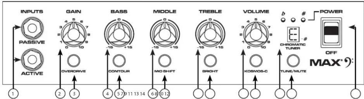
(1) ACTIVE/PASSIVE PICKUP Inputs
These 1/4 inputs are included so you can choose the appropriate setting for your instrument. The gain structure of the amplifier is modified to accommodate the outputs of different pickup configurations. The PASSIVE input is 10dB hotter than the ACTIVE input.
(2) GAIN
This knob controls input level to the preamp.
(3) OVERDRIVE
This crunch circuit is designed so that the volume of the amp will not change when the boost is switched on, but the distortion level will increase depending on the level of the GAIN knob. For best results, first set the distortion amount by adjusting the GAIN. Next, set the desired volume using the VOLUME knob. At this point, the clean volume will match if the Overdrive is turned off.
(4) BASS
This knob provides a shelving tone control for low frequencies and provides cut/boost of +/-15 dB. The center point is flat. The center frequency is 50Hz . -3 dB shelf corner frequency is 100Hz .
(5) CONTOUR
This button boosts highs and lows while simultaneously cutting mid tones, producing a "scooped" sound.
(6) MIDDLE
This knob provides a peaking tone control for Mid frequencies and cut/boost of +/-15dB. The center point is flat.
(7) MID SHIFT
This switch controls the center frequency of the MIDDLE knob. When the switch is OUT, the middle frequency is 600Hz . The middle frequency is 250Hz when the switch is pushed IN.
(8) TREBLE
This knob provides a shelving tone control for high frequencies and cut/boost of +/-15dB . The center point is flat and the frequency is 6 KHz. -3dB; the shelf corner frequency is 4 KHz.
(9) BRIGHT SWITCH
This button provides a 10 dB boost to frequencies above 1KHz. To activate, depress the switch to its "IN" position.
(10) VOLUME
This knob controls the overall volume of the amplifier.
(11) KOSMOS-C Subharmonic Generator
This Kosmos-C Low enhancement works by creating harmonics of signals in the bottom octave, where speakers are usually ineffective. The harmonics are more easily reproduced, resulting in a perception of stronger bass. The effect is source dependent; obviously a source with little energy in the bottom octave will not create booming bass.
(12) CHROMATIC TUNER (Not on Max 208)
Pressing the TUNE/MUTE button (13) will engage the chromatic tuner while muting the output to the speaker. The LED screen will indicate which note is being played while the red and green LEDs above the screen indicate whether the note is flat (red), sharp (red) or in tune (green).
(13) TUNE/MUTE (not available on Max 208)
Pressing this button will engage the chromatic tuner while muting the output to the speaker. The LED screen will indicate which note is being played while the red and green LEDs above the screen indicate whether the note is flat (red), sharp (red) or in tune (green). This switch also mutes the DI.
(14) POWER SWITCH
Rear Panel
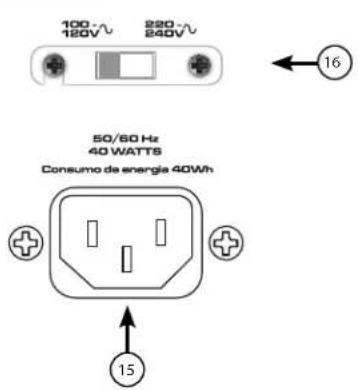

(15) AC POWER INLET:
This is the receptacle for an IEC line cord, which provides AC power to the unit. Connect the line cord to this connector to provide power to the unit. Damage to the equipment may result if improper line voltage is used. (See line voltage marking on unit).
Never break off the ground pin on any equipment. It is provided for your safety. If the outlet used does not have a ground pin, a suitable grounding adapter should be used, and the third wire should be grounded properly. To prevent the risk of shock or fire hazard, always make sure that the amplifier and all associated equipment is properly grounded.
NOTE: FOR UK ONLY
As the colors of the wires in the mains lead of this apparatus may not correspond with the colored markings identifying the terminals in your plug, proceed as follows: (1) The wire that is colored green and yellow must be connected to the terminal that is marked by the letter E, or by the Earth symbol, or colored green or green and yellow. (2) The wire that is colored blue must be connected to the terminal that is marked with the letter N, or the color black. (3) The wire that is colored brown must be connected to the terminal that is marked with the letter L, or the color red.
(16) LINE VOLTAGE SELECT SWITCH
This selector switch allows the amplifier to be operated at different line voltages. Please be sure this switch is set to the proper voltage for your area before connecting the amplifier to a power source or turning the amplifier on for the first time.

NEVER CHANGE THE POSITION OF THIS SWITCH WHILE THE AMPLIFIER IS TURNED ON.
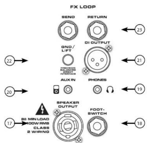
(17) SPEAKER OUTPUT JACK (Max 150, 250, and 300 only)
This combination 1/4'' / twist-lock connector is used to connect a speaker cable to the amplifier. The minimum load impedance on the amplifier is 8 .
(18) FOOTSWITCH JACK
The optional footswitch (part number 03022910) plugs into this jack. The footswitch controls OVERDRIVE and MUTE.
(19) HEADPHONE OUTPUT
1/8'' headphone output for personal monitoring.
(20) AUX INPUT
This 1 / 8^ input jack allows you to connect a CD player or MP3 player to your MAX* Series bass amp and play along
(21) PRECISION BALANCED DIRECT INTERFACE
This XLR output is used to connect the Max pre amp section to external equipment, such as mixing consoles, external power amplifiers, or recording equipment. This novel circuit provides a perfectly balanced and noise-free signal with none of the problems associated with small transformers.
(22) DI GND LIFT SWITCH
This switch may be used to eliminate hum caused by ground loops between the amplifier and other equipment, such as a mixing console.
(23) FX LOOP
The effects loop consists of the SEND and RETURN jacks, which are used to patch external effects processors post EQ in the signal chain. Connect the SEND jack to the input of effects processors. Connect the RETURN jack to the output of effects processors. The EF- FECTS SEND and RETURN jacks can also be used as a line level unbalanced preamp output and power amp input jacks, respectively.
Rear Panel
POWER CONSUMPTION:
(1/8 rated power, 1KHz sine wave)
120vac/60Hz, 230vac/50Hz
MAX208=33W
MAX 100 = 50W
MAX 150 = 33W
MAX 250 = 63W
MAX 300 = 78W
POWER AMPLIFIER:
(Rated Power)--Continuous RMS
(1% THD, 1KHz sine wave, nominal line)
MAX 100 = 60W (rms) into 8 ohms
MAX 150 = 120W (rms) into 4 ohms
MAX 250 = 150W (rms) into 4 ohms
MAX 300 = 200W (rms) into 3 ohms
MAX 208 = 120W (rms) into 4 ohms
PRE-AMPLIFIER:
Maximum Input Sensitivity:
(PRE GAIN = 10, LOW/MID/HIGH = 5, VOLUME = 10, all voicing switches defeated)
Passive Input 11mV / -36.95dBu 30mV / -28.24dBu 40mV / -25.74dBu
Active Input same as passive 90mV / -18.70dBu 110mV / -16.95dBu
Auxiliary Input 420mV / -5.32dBu 900mV / 1.3dBu 1.0V / 2.22dBu
Nominal Input Sensitivity:
(PRE GAIN = 5, LOW/MID/HIGH = 5, VOLUME = 5, all voicing switches defeated)
Passive Input 290mV / -8.53dBu 400mV / -5.74dBu 500mV / -3.8dBu
Active Input same as passive 1.10V / 3.05dBu 1.40V / 5.14dBu
Auxiliary Input same as maximum 1.80V / 7.32dBu 2.10V / 8.66dBu
Headphone Output:
(Mono)
50mW x 2 into 8-ohm minimum load
Direct Interface (DI):
Pre-EQ, unity buffer
Output Signal Level = Input Level-10dB
Noise Floor = 0.95mV(rms) = -78dBu
Dimensions:
(HxWxD)
Max 100 - 18.0"x15.7"x13.2" - 23.8lb
Max 150 - 19.0"x16.5"x14.2" - 29.2lb
Max 208 - 23.2"x12.3"x13.2" - 32.2lb
Max 250-22.8"x19.4"x16.2" - 44.4lb
Max 300-22.8"x19.4"x16.2" -46.4lb

www.peavey.com
Warranty registration and information for U.S. customers available online at
www.peavey.com/warranty or use the QR tag below

Features and specifications subject to change without notice.
Peavey Electronics Corporation
5022 Hartley Peavey Drive
Meridian, MS 39305
(601)483-5365
FAX (601)486-1278
T
MAX® 系列低音放大器
操作手册
中文
MAX® 系列低音放大器
As the colors of the wires in the mains lead of this apparatus may not correspond with the colored markings identifying the terminals in your plug, proceed as follows: (1) The wire that is colored green and yellow must be connected to the terminal that is marked by the letter E, or by the Earth symbol, or colored green or green and yellow. (2) The wire that is colored blue must be connected to the terminal that is marked with the letter N, or the color black. (3) The wire that is colored brown must be connected to the terminal that is marked with the letter L, or the color red.
(16) LINE VOLTAGE SELECT(线路电压选择)开关
Warranty registration and information for U.S. customers available online at
www.peavey.com/warranty
or use the QR tag below

Features and specifications subject to change without notice.
Peavey Electronics Corporation
5022 Hartley Peavey Drive
Meridian, MS 39305
(601)483-5365
FAX (601) 486-1278
(15)ENTRÉD'ALIMENTATION AC:
As the colors of the wires in the mains lead of this apparatus may not correspond with the colored markings identifying the terminals in your plug, proceed as follows: (1) The wire that is colored green and yellow must be connected to the terminal that is marked by the letter E, or by the Earth symbol, or colored green or green and yellow. (2) The wire that is colored blue must be connected to the terminal that is marked with the letter N, or the color black. (3) The wire that is colored brown must be connected to the terminal that is marked with the letter L, or the color red.
(16) BOUTON DE SELECTION DE TENSION DE LIGNE
MAX 150 = 33W
MAX 250 = 63W
MAX 300 = 78W
AMPLIFICATEUR DE PUISSANCE:
Warranty registration and information for U.S. customers available online at
www.peavey.com/warranty
or use the QR tag below

Features and specifications subject to change without notice.
Peavey Electronics Corporation
5022 Hartley Peavey Drive
Meridian, MS 39305
(601)483-5365
FAX (601) 486-1278

Logo referenced in Directive 2002/96/EC Annex IV
(OJ)L37/38,13.02.03 and defined In EN 50419:2005
The bar is the symbol for marking of new waste and
is applied only to equipment manufactured after
13 August 2005
Bassverträker Serie MAX®
Betriebsanleitung


DEUTSCH
Bassverträker Serie MAX®
As the colors of the wires in the mains lead of this apparatus may not correspond with the colored markings identifying the terminals in your plug, proceed as follows: (1) The wire that is colored green and yellow must be connected to the terminal that is marked by the letter E, or by the Earth symbol, or colored green or green and yellow. (2) The wire that is colored blue must be connected to the terminal that is marked with the letter N, or the color black. (3) The wire that is colored brown must be connected to the terminal that is marked with the letter L, or the color red.
MAX 150 = 33W
MAX 250 = 63W
MAX 300 = 78W
Warranty registration and information for U.S. customers available online at
www.peavey.com/warranty
or use the QR tag below

Features and specifications subject to change without notice.
Peavey Electronics Corporation
5022 Hartley Peavey Drive
Meridian, MS 39305
(601)483-5365
FAX (601) 486-1278
As the colors of the wires in the mains lead of this apparatus may not correspond with the colored markings identifying the terminals in your plug, proceed as follows: (1) The wire that is colored green and yellow must be connected to the terminal that is marked by the letter E, or by the Earth symbol, or colored green or green and yellow. (2) The wire that is colored blue must be connected to the terminal that is marked with the letter N, or the color black. (3) The wire that is colored brown must be connected to the terminal that is marked with the letter L, or the color red.
MAX 150 = 33W
MAX 250 = 63W
MAX 300 = 78W
AMPLIFICATORE DI POTENZA:
MAX 100 = 60W (rms) in 8 ohm
MAX 150 = 120W (rms) in 4 ohm
MAX 250 = 150W (rms) in 4 ohm
MAX 300 = 200W (rms) in 3 ohm
MAX 208 = 120W (rms) in 4 ohm
PRE-AMPLIFICATORE:
Warranty registration and information for U.S. customers available online at
www.peavey.com/warranty
or use the QR tag below

Features and specifications subject to change without notice.
Peavey Electronics Corporation
5022 Hartley Peavey Drive
Meridian, MS 39305
(601)483-5365
FAX (601) 486-1278
MAX® フリー�es バームフ
才レ一
マ 二人乃


日本語
MAX® フリーヒス バーフアング
As the colors of the wires in the mains lead of this apparatus may not correspond with the colored markings identifying the terminals in your plug, proceed as follows: (1) The wire that is colored green and yellow must be connected to the terminal that is marked by the letter E, or by the Earth symbol, or colored green or green and yellow. (2) The wire that is colored blue must be connected to the terminal that is marked with the letter N, or the color black. (3) The wire that is colored brown must be connected to the terminal that is marked with the letter L, or the color red.
(16)拉伊爾電圧選択スイチ
(22)DI GlaLUnDriFbUsIy
DAILeKToINtAnFEs (DI)
PRIEQ、二二三巴FF
/ɪsF□ə=0.95mV(rms)=-78dBu
寸法:
Warranty registration and information for U.S. customers available online at
www.peavey.com/warranty
or use the QR tag below

Features and specifications subject to change without notice.
Peavey Electronics Corporation
5022 Hartley Peavey Drive
Meridian, MS 39305
(601)483-5365
FAX (601) 486-1278
MAX®


韩国
MAX® マリズiblyス広
iNnBnHnEeHnEeHnEeHnEeHnEeHnEeHnEeHnEeHnEeHnEeHnEeHnEeHnEeHnEeHnEeHnEeHnEeHnEeHnEeHnEeHnEeHnEeHnEeHnEeHnEeHnEaeHnEaeHnEaeHnEaeHnEaeHnEaeHnEaeHnEaeHnEaeHnEaeHnEaeHnEaeHnEaeHnEaeHnEaeHnEaeHnEaeHnEaeHnEaeHnEaeHnEaeHnEaeHnEaeHnEaeHnEaeHnEee
As the colors of the wires in the mains lead of this apparatus may not correspond with the colored markings identifying the terminals in your plug, proceed as follows: (1) The wire that is colored green and yellow must be connected to the terminal that is marked by the letter E, or by the Earth symbol, or colored green or green and yellow. (2) The wire that is colored blue must be connected to the terminal that is marked with the letter N, or the color black. (3) The wire that is colored brown must be connected to the terminal that is marked with the letter L, or the color red.
(20) AUX INPUT(把子用到)1/8" 18" 18" 18" 18" 18" 18" 18" 18" 18" 18" 18" 18" 18" 18" 18" 18" 18" 18" 18" 18" 18" 18" 18" 18" 18" 20"
(21) PRECISION BALANCED DIRECT INTERFACE(通信用膜膜式膜片膜片膜片膜片膜片膜片膜片膜片膜片膜片膜片膜片膜片膜片膜片膜片膜片膜片膜片膜片膜片膜片膜片膜片膜片膜片膜片膜片膜片膜片膜片膜片膜片膜片膜片膜片膜片膜片膜片膜片膜片膜片膜片膜片膜片膜片膜片膜片膜片膜片膜
XLR
i
(22)DI GND LIFT SWITCH(DI上拉元德拉克斯万切)
i
(23) FX LOOP(FX 单元)
IEK 50123 50123 50123 50123 50123 50123 50123 50123 50123 50123 50123 50123 50123 50123 50123 50123 50123 50
辛田
MAX 208 = 4Ω·120W(rms)
三
到中
DI(Direct Interface):
EQR
叠默释间互比 10dB
Warranty registration and information for U.S. customers available online at
www.peavey.com/warranty
or use the QR tag below

Features and specifications subject to change without notice.
Peavey Electronics Corporation
5022 Hartley Peavey Drive
Meridian, MS 39305
(601)483-5365
FAX (601) 486-1278
As the colors of the wires in the mains lead of this apparatus may not correspond with the colored markings identifying the terminals in your plug, proceed as follows: (1) The wire that is colored green and yellow must be connected to the terminal that is marked by the letter E, or by the Earth symbol, or colored green or green and yellow. (2) The wire that is colored blue must be connected to the terminal that is marked with the letter N, or the color black. (3) The wire that is colored brown must be connected to the terminal that is marked with the letter L, or the color red.
120vca/60Hz, 230vca/50Hz
MAX 208 = 33W
MAX 100 = 50W
MAX 150 = 33W
MAX 250 = 63W
MAX 300 = 78W
AMPLIFICADOR DE POTÊNCIA:
Warranty registration and information for U.S. customers available online at
www.peavey.com/warranty
or use the QR tag below

Features and specifications subject to change without notice.
Peavey Electronics Corporation
5022 Hartley Peavey Drive
Meridian, MS 39305
(601)483-5365
FAX (601) 486-1278
As the colors of the wires in the mains lead of this apparatus may not correspond with the colored markings identifying the terminals in your plug, proceed as follows: (1) The wire that is colored green and yellow must be connected to the terminal that is marked by the letter E, or by the Earth symbol, or colored green or green and yellow. (2) The wire that is colored blue must be connected to the terminal that is marked with the letter N, or the color black. (3) The wire that is colored brown must be connected to the terminal that is marked with the letter L, or the color red.
(16) LINE VOLTAGE SELECT SWITCH
MAX 150 = 33W
MAX 250 = 63W
MAX 300 = 78W
Warranty registration and information for U.S. customers available online at
www.peavey.com/warranty
or use the QR tag below

Features and specifications subject to change without notice.
Peavey Electronics Corporation
5022 Hartley Peavey Drive
Meridian, MS 39305
(601)483-5365
FAX (601) 486-1278