USER MANUAL MC 130 Classic Kärcher
natural_image
Exterior view of a modern street cleaning spray truck (MC 130) with visible brushwork and control panel (no signage or text beyond license plate)
Inhalt
Anschlüsse vorne (Linearhydraulik)
Anschlüsse rechts
natural_image
Close-up of industrial machinery components with hoses and connectors (no visible text or symbols)
natural_image
Close-up of industrial machinery components with hoses and connectors (no visible text or symbols)
natural_image
Close-up of mechanical components with hoses and connectors, labeled 1 and 2 (no text or symbols beyond labels)
natural_image
Close-up of a red plastic pushpin on a mechanical component, labeled with number 1 (no text or symbols on the object itself)
①Funktionstasten
natural_image
Close-up of a black mechanical component with threaded end and protruding shaft (no visible text or symbols)
natural_image
3D mechanical assembly diagram showing internal pipes and tubing (no text or symbols)
natural_image
Black rectangular electronic device with a central display and metallic connectors (no visible text or symbols)
natural_image
Close-up of a black rectangular electronic device with a central display and metallic connectors (no visible text or symbols)
natural_image
Mechanical assembly diagram showing a shaft and mounting bracket with numbered components (1, 2, 3), no readable text or symbols present.
natural_image
Close-up of a mechanical component with labeled parts (1, 2, 3), no readable text or symbols beyond numbered annotations
natural_image
Close-up of a black industrial machine component mounted on a wooden floor, with no visible text or symbols.
① Pedal Besenanpressdruck
natural_image
Industrial equipment setup with hoses and tubing, no visible text or symbols
①Verschluss
Chairman of the Board of Management

S. Reiser
Director Regulatory Affairs & Certification
71364 Winnenden (Germany)
Tel.: +49 7195 14-0
Fax: +49 7195 14-2212
Winnenden, 2017/07/18
natural_image
Close-up of mechanical components with no visible text or symbols
natural_image
Close-up of mechanical components with hoses and connectors, no visible text or symbols
①Fanghaken
②Anbaurahmen
natural_image
Close-up of a gray industrial vehicle showing internal components and a numbered annotation (1), no readable text or symbols present.
①Wasseranschlüsse
natural_image
Close-up of industrial machinery components with visible wiring and numbered labels (no readable text or symbols)
natural_image
Close-up of a mechanical assembly with visible components and numbered labels (1, 2), no readable text or symbols beyond labels.
natural_image
Close-up of a gray industrial vehicle showing internal components and a numbered annotation (1), no readable text or symbols present.
①Wasseranschlüsse
natural_image
Close-up of a mechanical component with visible wiring and a warning symbol (no readable text or labels)
①
natural_image
Close-up of a car's seatbelt mechanism with warning symbol and arrows indicating components (no readable text or labels)
②
③
(1)Stange
(2)Verriegelungshebel
natural_image
Industrial robotic arm with yellow safety guard and white plastic components, no visible text or symbols
①Seitenbesenarm
②Anschlag
natural_image
Mechanical vehicle with two large wheel heads mounted on a yellow support structure (no visible text or symbols)
natural_image
Close-up of a mechanical cleaning or cleaning device with labeled parts (1, 2), showing brush and mesh components without any readable text or symbols.
①Aufbewahrungsbox
①Verriegelungshebel
natural_image
Close-up of a mechanical assembly with red and green components, no visible text or symbols
natural_image
Close-up of mechanical components with a numbered annotation pointing to a tool (no readable text or symbols)
①Verriegelungshebel
natural_image
Close-up of a mechanical device with multiple connectors and tubing, showing two circled components (no visible text or symbols)
natural_image
Mechanical assembly diagram showing a shaft and housing with numbered components (no readable text or symbols)
natural_image
Diagram of a vehicle chassis with two wheels and internal components (no text or symbols)
natural_image
3D mechanical assembly diagram showing a robotic arm with labeled parts (1 and 2), no readable text or symbols present.
natural_image
Industrial robotic pallet with labeled parts (1 and 2), no visible text or symbols on the machinery itself.
natural_image
Mechanical assembly diagram showing a component with numbered parts and an arrow indicating motion (no text or symbols present)
natural_image
Diagram of a bicycle's front wheel assembly showing two wheels with brake calipers and suspension components (no text or labels)
natural_image
Mechanical assembly diagram showing a rotating component with labeled parts (1 and 2), no readable text or symbols present.
natural_image
Side view of a cleaning or cleaning service vehicle with labeled components (no text or symbols visible)
natural_image
Close-up of mechanical components with no visible text or symbols
①Bypassventile

① Saugschlauch
natural_image
Close-up of a device's internal panel with red arrows pointing to a button, showing no visible text or symbols.
natural_image
Top-down view of a vehicle chassis showing rear-mounted electronic equipment with labeled parts (no readable text or symbols)
①Deckel
②Ausgleichsbehälter
natural_image
Close-up of a mechanical component with an inset showing a close-up view of a component (no visible text or symbols)
natural_image
Technical diagram of a vehicle's wheel assembly with labeled parts (1 and 2), showing components like tire, brake, and suspension components.
①Radmuttern
②Rad
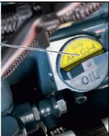
①Einfüllstutzen
natural_image
Close-up of an engine component with hoses and a valve (no visible text or symbols)
②
natural_image
Close-up of two views of a vehicle wheel rim and tire, labeled with numbered annotations (1–4), showing tread patterns and mounting brackets (no text or symbols beyond labels)
Chairman of the Board of Management

S. Reiser
Director Regulatory Affairs & Certification
71364 Winnenden (Germany)
Tel.: +49 7195 14-0
Fax: +49 7195 14-2212
Winnenden, 2018/07/18
Contents
Introduction 58
Intended use 58
Foreseeable misuse....59
Environmental protection 59
Safety information....59
Overview of the appliance....64
Initial startup....75
Operation 77
Attachments....84
2-brush sweeping system attachment kit (pulled).... 90
3-brush sweeping system attachment kit (front brush) .... 93
Transport....96
Care and maintenance....97
Storage 107
Troubleshooting guide.... 107
Accessories and spare parts.... 110
Technical data.... 110
EU Declaration of Conformity 112
Introduction
Read the original instructions and the safety instructions before using your vehicle for the first time. Act in accordance with them.
Keep these operating instructions for future reference or for future owners.
Checking the delivery
Please report any defects or shipping damage identified on the vehicle when it is handed over directly to your dealer or department store.
Scope of delivery
MC 130 vacuum sweepers (1.442-231.2)
MC 130 Classic vacuum sweepers
- Yanmar engine 42 hp
• Version with diesel particle filter
• Rear wheel drive (2WD)
MC 130 vacuum sweepers
- Yanmar engine 42 hp
• Version with diesel particle filter
• All-wheel drive (4WD)
MC 130 vacuum sweepers (1.442-234.2)
MC 130 Plus vacuum sweepers
• Kubota engine 70 hp
• Version with diesel particle filter
• All-wheel drive (4WD)
Warranty
The warranty conditions issued by our relevant sales company apply in all countries. We shall remedy possible malfunctions on your appliance within the warranty period free of cost, provided that a material or manufacturing defect is the cause. In a warranty case, please contact your dealer (with the purchase receipt) or the next authorised customer service site.
(See overleaf for the address)
Intended use
The following versions of the vehicle are described in these operating instructions.
- MC 130 Classic
MC 130
MC 130 Plus
The vehicle may only be used for the intended use, as illustrated and described in these operating instructions.
Intended use also includes adherence to the prescribed maintenance activities and intervals.
The vehicle and attachments may only be used, maintained and repaired by persons familiar with the vehicle and attachments and the associated hazards.
The legally applicable general safety and accident prevention regulations must be adhered to. All other safety regulations, occupational health care regulations and road traffic regulations must be adhered to.
The operating personnel must:
- Be physically and mentally suitable.
- Have been instructed in the handling of the vehicle and attachments.
- Have read and understood these operating instructions and the operating instructions for any attachments or towed machinery prior to starting work.
- Have provided the operating company with verification of capability to operate the vehicle.
- Be explicitly nominated to operate the vehicle by the operating company.
Vacuum sweeper
This vehicle is a vacuum sweeper.
The vacuum sweeper is intended for cleaning dirty outdoor surfaces.
The vehicle must conform to the applicable national regulations if used on public roads.
The vehicle is only suitable for use on the surfaces listed in the operating instructions.
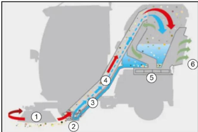
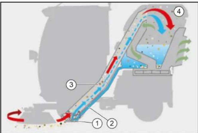
Vacuum sweeper function
flowchart
graph TD
    A["1"] --> B["2"]
    B --> C["3"]
    C --> D["4"]
    D --> E["5"]
    E --> F["6"]
    style A fill:#f9f,stroke:#333
    style B fill:#ccf,stroke:#333
    style C fill:#cfc,stroke:#333
    style D fill:#fcc,stroke:#333
    style E fill:#cff,stroke:#333
    style F fill:#ffc,stroke:#333
①Side brush
②Suction mouth
③Water circuit / recycling water
④Suction pipe
⑤ Waste container blower
⑥ Exhaust gas/ diffusor
- The dust created is bound by sprayed water.
- The side brushes rotate inwards and convey the waste in front of the suction mouth.
- The suction fan generates a vacuum and sucks the waste into the waste container.
- The filtered exhaust gas escapes from the rear side of the waste container.
- The dust is more effectively bound through the recycled water operation (water circulation).
Suitable sweeping surfaces
- Asphalt
- Industrial floor
- Screed
- Concrete
- Paving stones
Foreseeable misuse
Any type of improper use is prohibited.
The operating personnel are liable for hazards resulting from incorrect use. Using the vehicle for other purposes than those described in this documentation is prohibited.
No modifications must be made to the vehicle.
- Never sweep/vacuum explosive liquids, inflammable gases or undiluted acids and solvents. These include petrol, paint thinners or heating oil, which can form explosive vapours or mixtures through suction air turbulence, also acetone, undiluted acids and solvents because these attack the materials used in the machine.
- Never sweep or vacuum reactive metal dusts (e.g. aluminium, magnesium, zinc) because they form explosive gases in conjunction with highly alkaline or acidic cleaning agents.
- Never sweep or vacuum burning or smouldering objects.
- Do not remain in the hazard zone.
- Never operate the vehicle in potentially explosive environments.
- Never transport persons on the vehicle, the loading area or attachments.
- Do not use the vehicle as a front loader.
- Do not use the vehicle in the forestry industry.
- Do not use the vehicle for dispersing insecticide, pesticide or fertiliser.
Environmental protection
The packing materials can be recycled. Please dispose of packaging in accordance with the environmental regulations.
Electrical and electronic appliances contain valuable, recyclable materials and often components such as batteries, rechargeable batteries or oil, which - if handled or disposed of incorrectly - can pose a potential threat to human health and the environment. However, these components are required for the correct operation of the appliance. Appliances marked by this symbol are not allowed to be disposed of together with the household rubbish.
Notes on the content materials (REACH)
Current information on content materials can be found at: www.kaercher.com/REACH
Disposal
- Observe the national regulations at the location.
- Observe company-specific specifications.
- Dispose of any operating and auxiliary materials according to the valid safety data sheets.
Disposal of the worn out vehicle
Vehicles that are no longer fit for service contain valuable recyclable materials. We recommend you cooperate with a waste management company with regard to the disposal of your vehicle.
Hazard levels
⚠️DANGER
- Indication of an imminent threat of danger that will lead to severe injuries or even death.
⚠ WARNING
- Indication of a potentially dangerous situation that may lead to severe injuries or even death.
△CAUTION
- Indication of a potentially dangerous situation that may lead to minor injuries.
ATTENTION
- Indication of a potentially dangerous situation that may lead to damage to property.
General safety instructions
⚠️ DANGER ● Risk of asphyxiation. Keep packaging film out of the reach of children.
△ WARNING • Only use the vehicle for its proper use. Take into account the local conditions and beware of third parties, in particular children, when working. • Persons with reduced physical, sensory or mental capabilities, or those with a lack of experience
and knowledge, are only allowed to use the vehicle if they are supervised or have been instructed with respect to using the appliance safely, and understand the resultant dangers involved.
- Only people who have been instructed on how to use the vehicle, or have proven their ability to operate it, and have been explicitly instructed to use it, must use the vehicle. • Children must not operate the vehicle. • Children must be supervised to prevent them from playing with the vehicle.
⚠️ CAUTION • Safety devices are provided for your own protection. Never modify or bypass safety devices.
Safety instructions for driving
△ DANGER ● Danger of tilting if hill or slope is too steep! Observe the maximum permissible values in the technical data when driving up hills and slopes. ● Danger of tilting in case of excessive tilting at side! Observe the maximum permissible values in the technical data when driving lateral to the travel direction.
- Danger of tipping on unstable surfaces! Only use the vehicle on stable surfaces.
△ WARNING ● Risk of accident due to not adapting speed. Approach corners slowly. ● The list on the risk of overturning is not necessarily comprehensive.
△ CAUTION ● Driver cabins are equipped with air exit slats. Always keep these free from obstructions to ensure sufficient ventilation.
ATTENTION
Ensure free visibility on public roads before use (e.g. fog-proof windscreens, mirrors, etc.).
Diesel engine safety instructions
△ DANGER • Diesel engine: Never operate vehicles with diesel engines in confined spaces. • Danger of poisoning: Do not inhale the exhaust gases. • Never close off the exhaust gas openings. • Never bend down over the exhaust gas opening. Never reach inside the exhaust gas opening. • Always keep away from the drive area. Be aware of the engine after-running time after switching off (3-4 seconds).
Safety instructions for transportation
⚠ WARNING
- Pay attention to the weight of the vehicle to avoid accidents and injuries, see Chapter Technical data.
- Pay attention to the vehicle height during transport on a trailer or lorry and secure the vehicle, see Chapter Technical data.
Safety instructions for care and maintenance
- Switch off the engine and remove the ignition key before performing cleaning or maintenance work on the vehicle, replacing parts or changing the functionality of the vehicle.
- Repairs may only be carried out by approved customer service sites or staff qualified in this area who are familiar with all relevant safety instructions.
- Adhere to the safety checks according to the applicable local regulations for mobile commercial vehicles.
- The articulated joint, tyres, radiator fins, hydraulic hoses and valves, seals, electrical and electronic components must not be cleaned using a high-pressure cleaner.
Additional operating safety instructions
Note
The information in this chapter is also provided on a supplementary sheet that must always be carried on the vehicle.
General
The vehicle has a hydrostatic drive and articulated steering. It therefore exhibits driving characteristics that are different to those of a motorcar.
⚠ WARNING
Danger of tipping over
Please note that the driving characteristics of a vehicle with articulated steering differ considerably from those of a motorcar.
Drive around curves at an even and appropriate speed. This applies, in particular, for driving uphill/downhill and driving across the face of a slope.
Be aware of the changes in the centre of gravity of the vehicle depending on attachments.
Adjust the travel speed to the ambient conditions when driving in a straight line and when driving around bends, e.g. road conditions and the load status.
Note decoupling of the front and rear part of the vehicle via a central pendulum joint.
Braking characteristics
Release the accelerator pedal provides a form of active braking. This differs from a motorcar where only the engine brake reduces vehicle speed.
ATTENTION
The braking force applied when you release the accelerator pedal is weaker in higher gears and stronger in lower gears.
The braking force applied when you release the accelerator pedal in transport mode is significantly weaker than in working mode.
Steering characteristics
Vehicles with articulated steering exhibit a more direct response to steering movements than motorcars, particularly when taking bends at high speed, on snow, ice and wet/loose ground as well as during turning manoeuvres on slopes. Avoid rapid successive steering movements.
Centre of gravity / pendulum characteristics
Rear attachments and load statuses influence the vehicle's centre of gravity and the driving characteristics. You must be ready to adjust to changed driving characteristics, particularly after changing attachments and in the case of changeable load statuses. Limit ranges may be reached earlier.
The vehicle has a central pendulum joint to provide a high degree of all-terrain mobility. This enables both vehicle halves to move transversely to the travel direction independently from one another.
This special property means that the driver does not receive immediate feedback on the behaviour of the rear half of the vehicle. You should therefore take care to use the mirrors to keep an eye on the rear of the vehicle.
Safety instructions for sweepers with high dumping
△ DANGER ● Risk of injury on sweepers with high dumping Secure the lifted waste container before working. Fit the retainer only from outside the hazard zone.
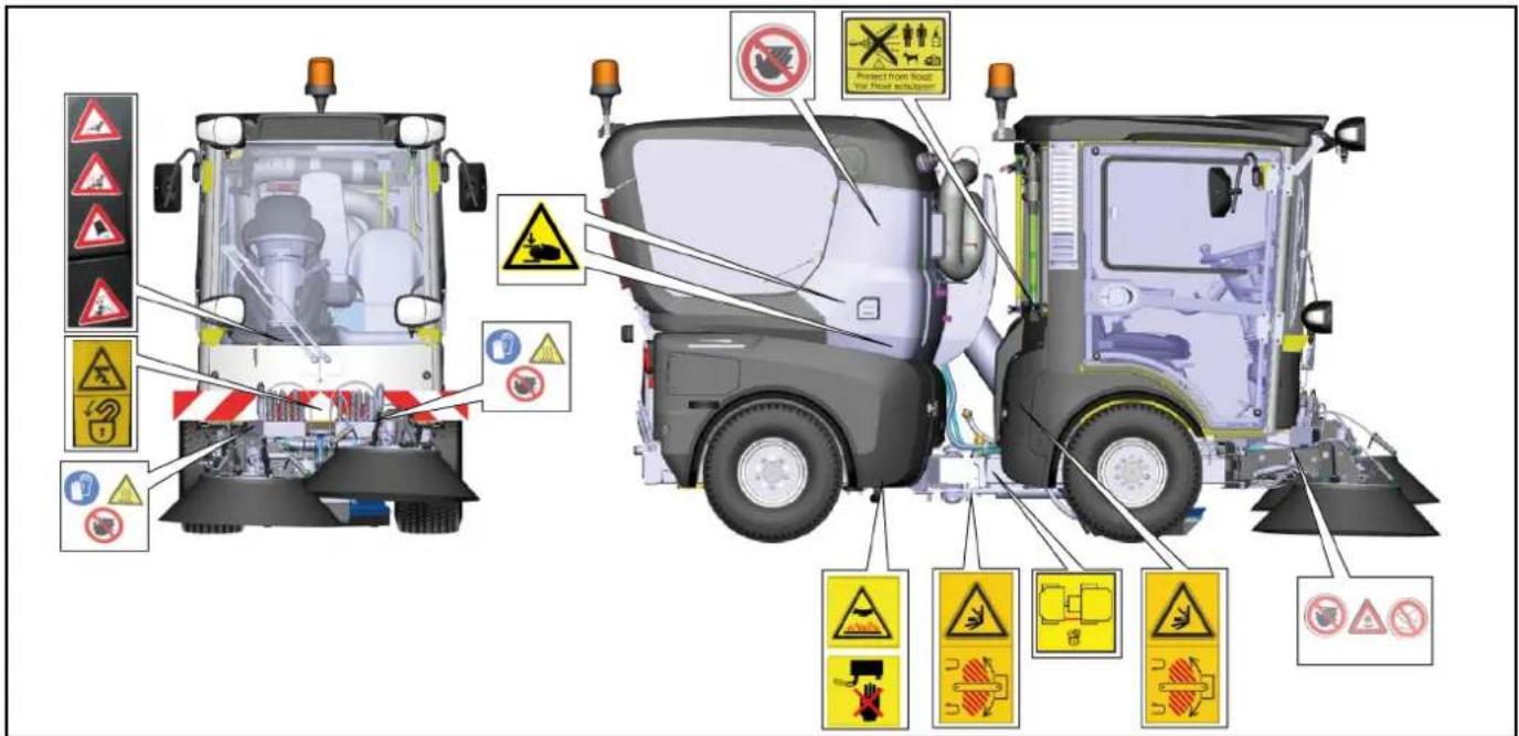
Symbols on the vehicle
Note
Replace the symbols immediately if they become illegible or get lost.
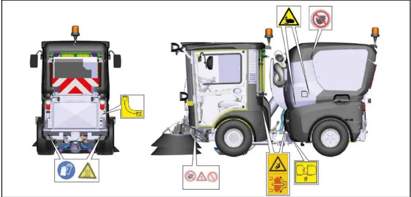
 | △DANGERRisk of burns from hot surfacesAllow the vehicle to cool down before working on it. |
 | △DANGERRisk of burns due to hot exhaust pipeDo not touch the exhaust pipe.Before working, allow the exhaust pipe to cool down. |
 | |
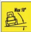 | △DANGERDanger of tiltingOnly drive on terrain with a maximum lateral incline of 10°. |
| △DANGERRisk of injury on account of splashing objectsKeep an adequate distance from persons, animals and objects. |
| △WARNINGRisk of injuryRisk of being squeezed or hurt at the belts, side-brushes, waste container, cover. |
| △DANGERDanger of crushingMake sure that no persons are present in the vicinity of the articulated joint or vehicle during operation.When using the vehicle for towing, make sure that no persons are located during operation between vehicle and trailer. |
| △DANGERRisk of injury from rotating partsOpen the bonnet only when the motor has come to a halt. |
| ATTENTIONDamage from incorrect transportDuring the transport, place always the transport lock on the articulated joint. |
| △WARNINGHealth risk due to poisonous exhaust gasesDo not inhale exhaust gases. |
| △DANGERRisk of injury due to unauthorised usageRemove the ignition key to protect against unauthorised use and prior to cleaning and maintenance work. |
| ATTENTIONSafety for cleaning and maintenancePrior to cleaning and maintenance work, park the vehicle on a level and firm subsurface. |
| △DANGERDanger of injury due to use of unspecified locations for seatingSit exclusively on the driver's seat. |
| △DANGERRisk of injury due to rolling overNo persons may be present in the vicinity of the vehicle during use. |
| △DANGERRisk of impact, risk of crushingWhen transporting or working under suspended loads, use suitable means for supporting. |
| △DANGERDanger of tiltingOnly empty the waste container when the vehicle is placed on a level and firm subsurface. |
| △DANGERRisk of fireDo not sweep up burning or glowing objects such as cigarettes, matches or similar objects. |
| △DANGERRisk of crushingKeep your hands away from this area. |
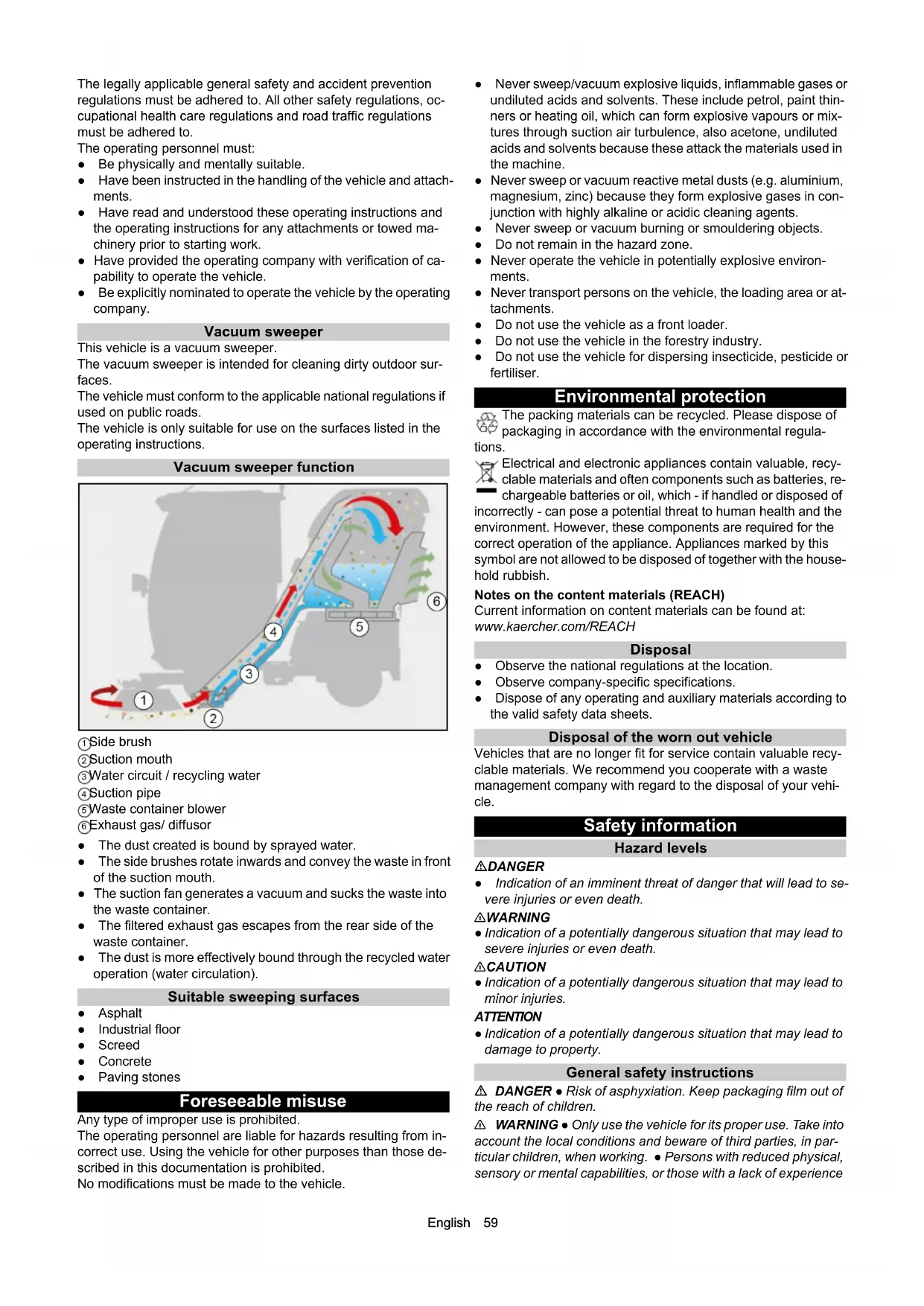
| Main switch (battery isolation switch) |
| Lubrication point |
| Lubricating strip |
| Lashing point |
| Quality of the brake fluid and position where brake fluid can be filledPosition of container for brake fluid |
| Locating point for a jack or a support |
| Position of main fuse |
| Position of fuse F2 |
| Emergency exit |
| Read operating instructions |
| Wear protective gloves |
| △WARNINGRisk of injury from high-pressure jetDo not direct the high-pressure jet at persons, animals, live electrical equipment or at the device itself.Protect the device high-pressure cleaner frost. |
| △DANGERRisk of injury from rotating brushesEnsure that no persons are in the vicinity of the danger zone. |
| ATTENTIONRisk of injury from the machine rolling awayAlways apply the parking brake when parking the machine. |
| △DANGERClimbing prohibitedTip the waste container only when nobody is in the hazard zone. |
 | △DANGERTipping prohibitedAttach the sweeper attachment only when in the operating position. |
 | ATTENTIONThe machine drives only when the waste container is retracted. |
 | ATTENTIONClimbing prohibitedDo not climb on the machine. |
 | △WARNINGRisk of injuryTip the waste container only on a level surface. |
Position of the symbols on the vehicle
Note
Immediately replace illegible or absent symbols.
Safety devices
Safety devices protect the user and may not taken out of operation or functionally circumvented.
Adhere to the safety instructions in the chapters!
Main switch
The main switch interrupts the electrical supply line to the starter motor.
Always disconnect the battery after parking the vehicle (Battery disconnected position).
Start lock
Prerequisites for starting the motor:
- Main switch activated (position battery connected)
- Driver is sitting on the driver's seat
When the driver's seat is vacant:
• The vehicle cannot be driven.
• The front PTO cannot be switched on or off.
Parking brake
The parking brake requires hydraulic pressure to release.
The parking brake is therefore applied when the engine is switched off.
The parking brake is also applied when the engine is running and the travel direction lever is in the NEUTRAL position.
Note
The "Parking brake applied" warning light in the multifunction display lights up when the parking brake is applied.
Driver cabin
The operator is protected from lightning strikes when sitting in the driver cabin.
The driver cabin has a roll-over protection structure (ROPS), which prevents rolling over after tipping over.
The driver cabin does not have a structure providing protection from falling objects (FOPS).
The driver cabin does not have a structure providing protection from falling objects (OPS).
Always use the safety belt.
Batteries / chargers
ATTENTION
Only use the batteries and chargers recommended by the manufacturer
Only replace batteries with batteries of the same type. Before disposing of the vehicle, remove the battery and dispose of it in accordance with national or local regulations.
Warning symbols
Observe the following warnings when handling the batteries:
 | Observe notes in the instructions for the battery, on the battery and in these operating instructions. |
 | Wear eye protection. |
 | Keep acids and batteries away from children. |
 | Risk of explosion |
 | Fire, sparks, open flames and smoking are prohibited. |
 | Risk of acid burns |
 | First aid. |
 | Warning |
 | Disposal |
 | Do not throw batteries in the bin. |
Safety instructions
△DANGER
Risk of fire and explosion
Do not place tools or other objects on the battery.
Naked flames and smoking must be strictly avoided.
Ensure the room is well ventilated when charging batteries.
Only use batteries and chargers approved by Kärcher (original spare parts).
△WARNING
Environmental risk due to improper disposal of batteries
Ensure that defect or used batteries are disposed of safely (contact a waste management company or Kärcher Service).
Procedures in the event of unintentional release of battery acid
When used normally, and when observing the instructions, lead-acid batteries do not pose any risk.
However, keep in mind that lead-acid batteries contain sulphuric acid which can cause serious chemical burns and corrosion.
- If there is spillage or, if the battery is leaking, acid is escaping, lay down a binding agent such as sand. Do not let it reach the sewer system, soil or a body of water.
- Neutralise the acid with lime/baking soda and dispose of it according to local regulations.
- Contact a waste management company to dispose of faulty batteries.
- Rinse out your eyes or rinse off your skin with copious amounts of fresh water if acid splashes into your eyes or onto your skin.
- Then consult a doctor immediately.
- Wash any contaminated clothing with water.
- Change clothes.
Overview of the appliance
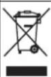
Front side view (passenger side)
① Sweeping system Left side brush
② Sweeping system Right side brush
③Front left hydraulic connection
④Front right hydraulic connection
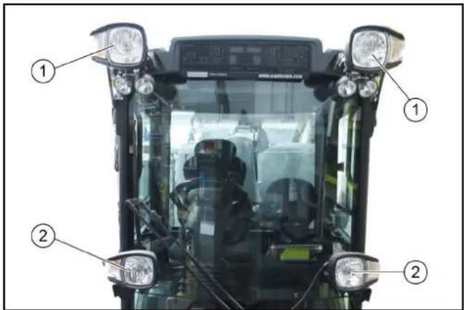
⑤Driving light/flasher
⑥Driving light/flasher
⑦Windscreen wiper
⑧ Working light
⑨Licence plate bracket
⑩ Working light
⑪Rear-view mirror
⑫Passenger door, lockable
⑬Waste container
⑭Fuel cap
⑮Left-hand side cladding
⑯Rear wheel
17 Front wheel
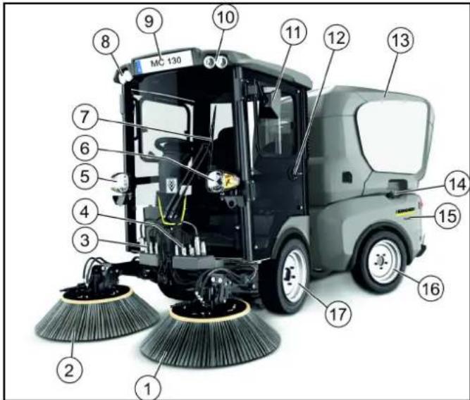
View with waste container on supports
①Rotating beacon warning lamp
② Waste container
③ Exhaust gas grille/diffusor
④Radiator protective grille
⑤Tail light/flasher
⑥Main switch
⑦ Right rear PTO hydraulic connection, 40l/min
⑧ Waste container rear support
⑨Trailer coupling (option)
⑩ Waste container rear support
⑪PTO return flow 40l/min
⑫ Tail light/flasher
⑬ Attachment frame with tilting function
⑭ Waste container side supports (2x)
⑮Driver cabin dust filter
⑯Driver cabin
⑰Licence plate bracket
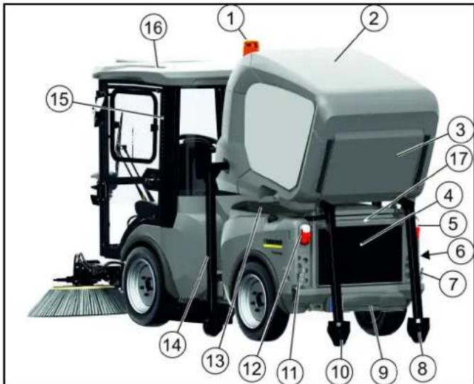
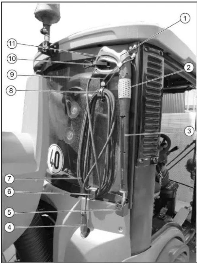
View with raised waste container (driver side)
① Waste container raised
②Manual suction hose storage
③Suction hose
④Driver cabin dust filter
⑤Rear-view mirror
⑥Side brush spray nozzle
⑦Side brush
⑧Driver cabin, lockable
⑨Front side panel cover
⑩ Transport lock articulated joint
⑪ Water system
⑫Recycling water hose
⑬Right side panel
⑭Rear hydraulic connection
⑮ Hydraulic connection for raising/lowering the waste container
Hydraulic connections
Definition of the term, hydraulic PTO
Power Take Off = hydraulic force output
Definition of the term, AUX
Auxiliary valve
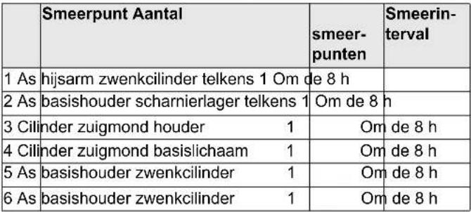
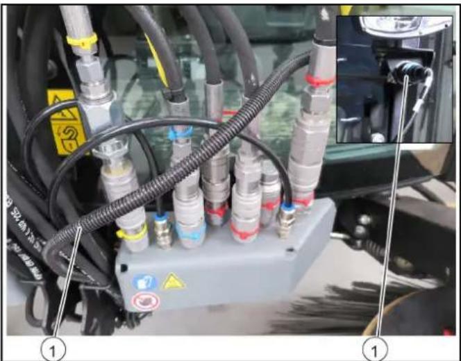
Front connections (linear hydraulics)
Right-hand side connections
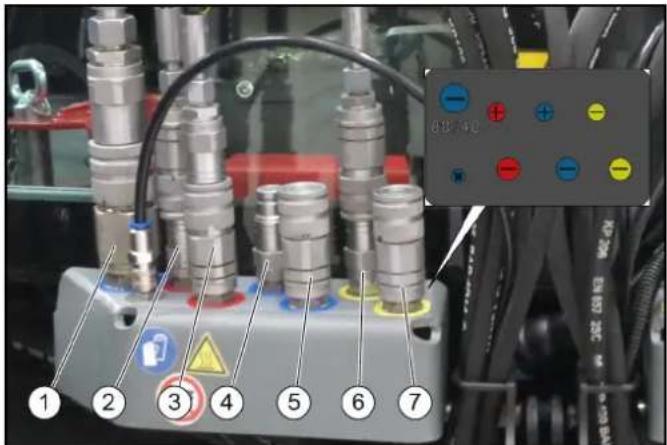
①PTO return flow
②Swivel in the side brush
③Swivel out the side brush
④Additional function (option)
⑤Additional function (option)
⑥Leakage oil
⑦Additional function (front power lift)
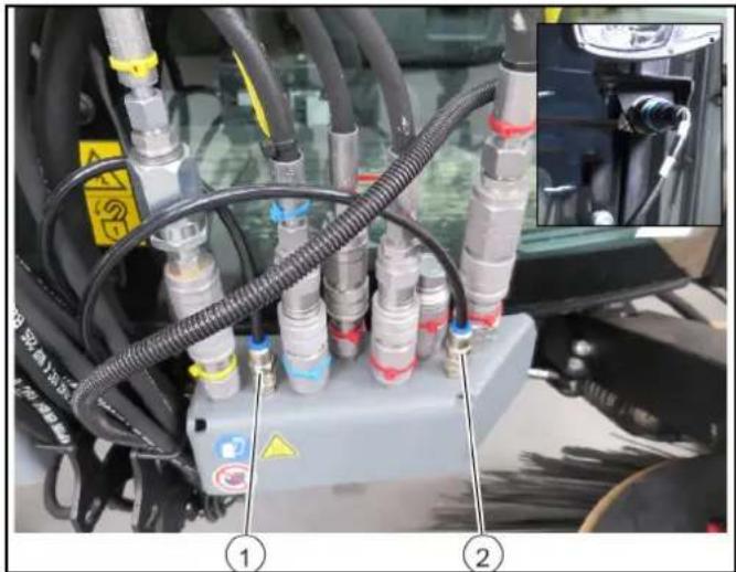
Left-hand side connections
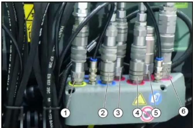
①Suction mouth/front power lift
②Raising the right and left brush arms together
③ Swivel in the side brush
④Swivel out the side brush
⑤Hydraulic PTO (80 l/min)
⑥Hydraulic PTO (40 l/min)
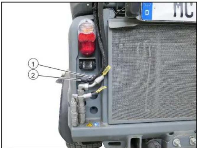
Rear connections
Right-hand side connections
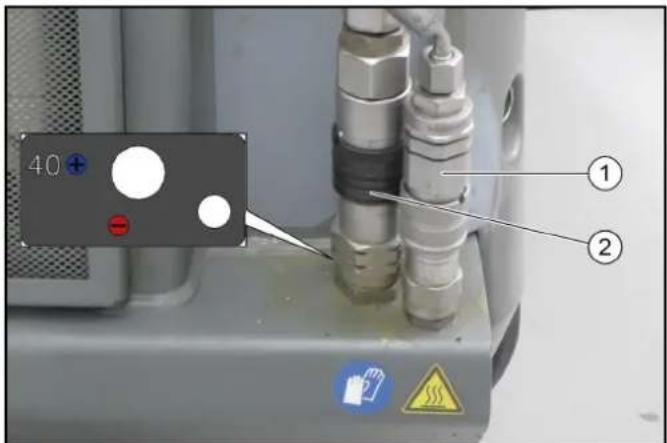
(1)AUX hydraulic connection, raise/lower
(2)Hydraulic PTO (40 l/min)
Left-hand side connections
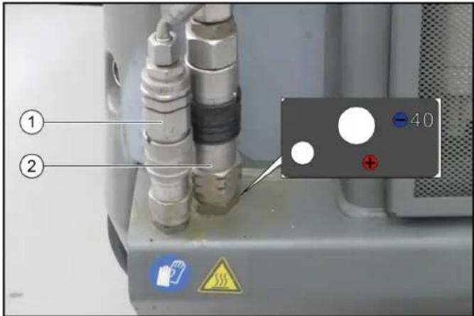
(1)AUX hydraulic connection, raise/lower
(2)Return line (40 l/min)
Electrical connections
Terminology electric PTO
Power Take Off = electric power output
Electrical connections for front attachment
natural_image
Close-up of industrial machinery components with hoses and connectors, no visible text or symbols
①Attachment detection
Electrical connections for rear attachment
①Attachment detection
②21-pin connection for rear attachment
Water connections
Spray water connections
Right-hand side connections
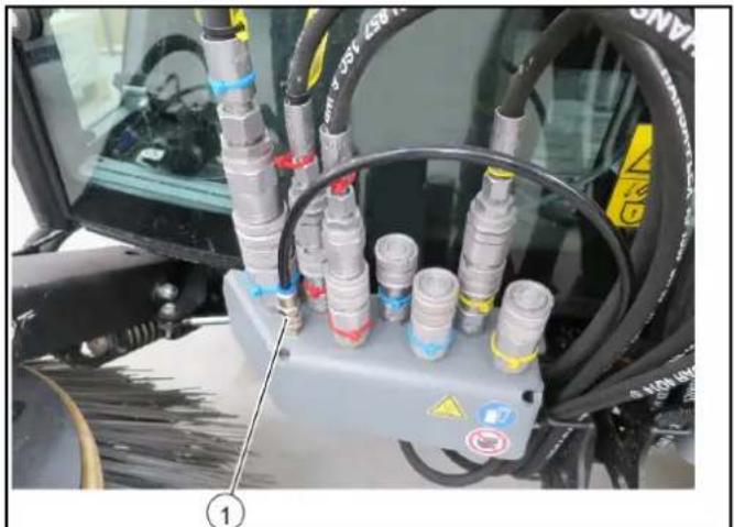
natural_image
Close-up of industrial machinery components with coiled hoses and a control panel (no visible text or symbols)
①Right side brush dust spray water
Left-hand side connections
natural_image
Close-up of industrial machinery components with hoses and connectors, no visible text or symbols
① Left side brush dust spray water
②Suction mouth spray water
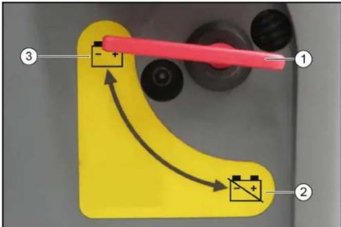
Main switch
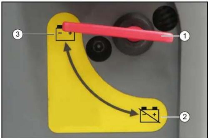
①Main switch
②Battery disconnected
③Battery connected
The main switch interrupts the electrical supply line to the starter motor.
If the main switch is pressed when the engine is running (battery disconnected), the engine will stop.
Always disconnect the battery when the vehicle is parked.
Emergency operation
The emergency operation hydraulic valve is located under a cover behind the driver cabin.
A description of this is provided in chapter Troubleshooting guide. This hydraulic valve is required when:
- The waste container/attachment frame cannot be raised because the device hydraulics have failed. For example when the engine fails.
- The front power lift/suction mouth cannot be raised because the device hydraulics have failed. For example when the engine fails.
- The parking brake spring actuator cannot be released, e.g. for towing the vehicle.
Waste container/attachment frame switchover
There are two different versions of the switch lever depending on the version of the vehicle.
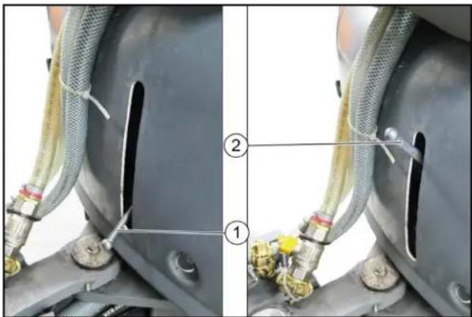
natural_image
Close-up of mechanical components with hoses and connectors, no visible text or symbols
①Switchover valve in the waste container position
② Switchover valve in the attachment frame position
The hydraulic system can be switched between the waste container and attachment frame via the switchover valve.
Note
The waste container and attachment frame are electronically monitored. Both functions cannot be activated simultaneously.
Driver cabin
Doors
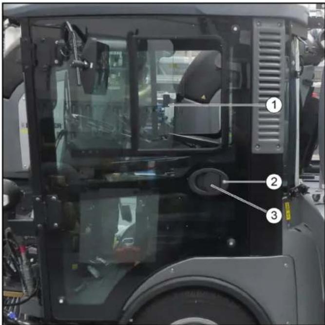
①Sliding windows
②Ignition key
③ Door handle
The driver's door is located at the left side in the travel direction, the emergency exit is located at the right side.
The door opener and door handles can be used as a aid for entering and exiting the cab.
Lock both doors with the ignition key after parking the vehicle.
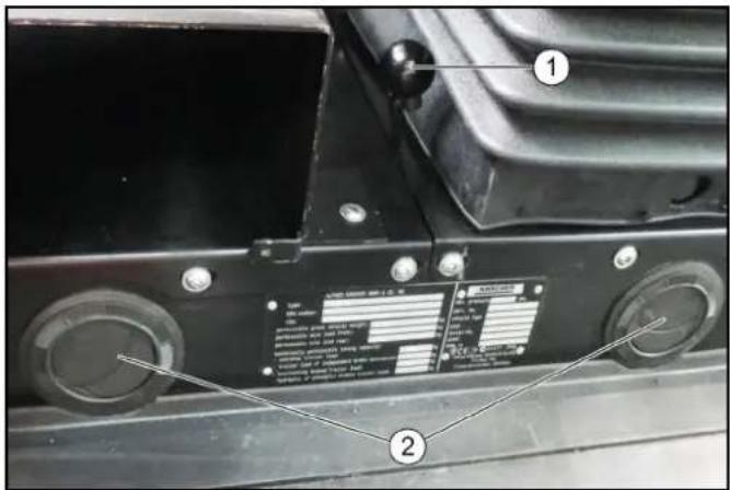
Storage compartment
A lockable storage compartment is located under the passenger seat. This can be used for storing documents, operating instructions, small parts or the towing eye.
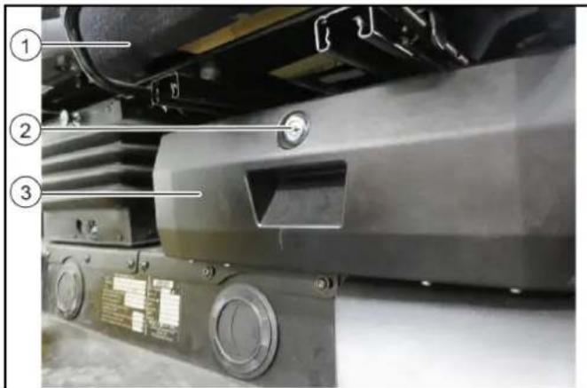
①Passenger seat
②Lock
③ Storage compartment
Emergency exit
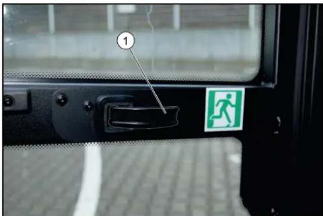
①Door handle
The emergency exit is located at the left side in the travel direction. Open the emergency exit by pulling the door handle.
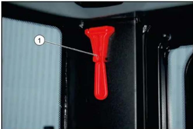
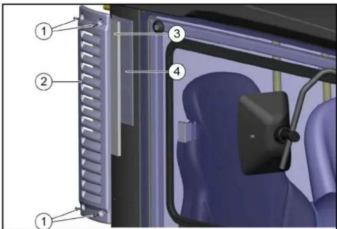
natural_image
Close-up of a red plastic pushpin inserted into a black mechanical component, with no visible text or symbols.
①Emergency hammer
The emergency hammer is located at the upper left, behind the passenger seat. In case of emergency, destroy the windscreen with the emergency hammer.
Interior lights
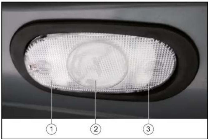
①Pressed down left: Lights switched on
②Centre position: The light is switched on when a door is opened
③Pressed down right: Lights switched off
Arm rest control panel
The control panel is located on the left arm rest of the driver's seat. The arm rest can be individually adjusted to suit the driver, see chapter.
For left-hand drive vehicles (optional), e.g. for the UK, the control panel is located on the right arm rest of the driver's seat.
Device carrier control assignments
Note
The indicators in the switches light when the switches are switched on.
①Front power lift joystick
- Raise front power lift and front PTO off (back)
– Lower front power lift and front PTO on (forwards)
- Operate AUX 1 (right/left)
– Switch on front power lift floating position (forwards)
– Switch off front power lift floating position (back)
②AUX 2 and AUX 3 joystick
- Operate AUX 2 (forwards/back)
- Operate AUX 3 (left)
③Not used
④ Hydraulic system on/off
⑤Electrical AUX 1, front
⑥ Electrical AUX 2, front
⑦Electrical AUX 1, rear
⑧Rear PTO 40 l/min
⑨Function ECO switches on the complete work programme and selects the last used values and settings.
⑩Electrical AUX 2, front
(A) Front PTO 40 l/min, 80 l/min
(B) Rear PTO 40 l/min
(C) Button for setting the engine speed
(D) Not used
(E) Not used
(F) Press the button to save set values or programs and open submenus.
(G) Rotary knob for changing values and selecting programs.
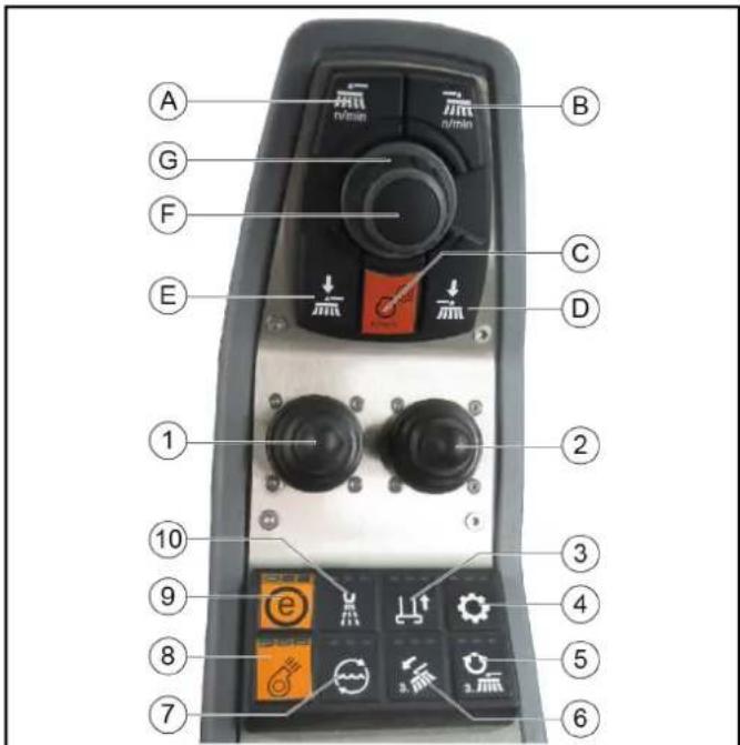
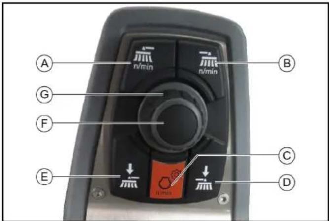
Control assignments for a vacuum sweeper with a 2-brush system
Note
The indicators in the switches light when the switches are switched on.

①Lowering/raising the sweeper system and switching the brushes on/off
② Lowering/raising the right side brush and switching the brushes on/off (optional)
③ Raise/lower suction mouth
④Hydraulic system on/off
⑤ Switching in the 3rd side brush (optional)
⑥3rd side brush inclination adjustment (optional)
⑦Water circulation function on/off (recycling water)
⑧Suction fan on/off
Note
The suction fan has an afterrun time of approx. 15 seconds after being switched off
⑨ ECO function
- Switches the complete work program on.
PTO (side brushes, suction fan), fresh water, water circulation (recycling water)
⑩Water pump on/off
(A) Left and right side brush speed button
For individual extraction (option), left side brush speed button
(B) For individual extraction (option), right side brush speed button
(C) Engine speed
Press to adjust the values
Note
The suction performance depends on the set engine speed.
• 1600 rpm light waste
• 2200 rpm normal soiling
• 2500 rpm strong, heavy soiling
(D) For individual extraction (option), right side brush contact pressure button
(E) Left-hand and right-hand side brush contact pressure button For individual extraction (option), left side brush contact pressure button
(F) Save button
Press to save adjusted values or programs
(G) Rotary knob
Press to change the adjusted values
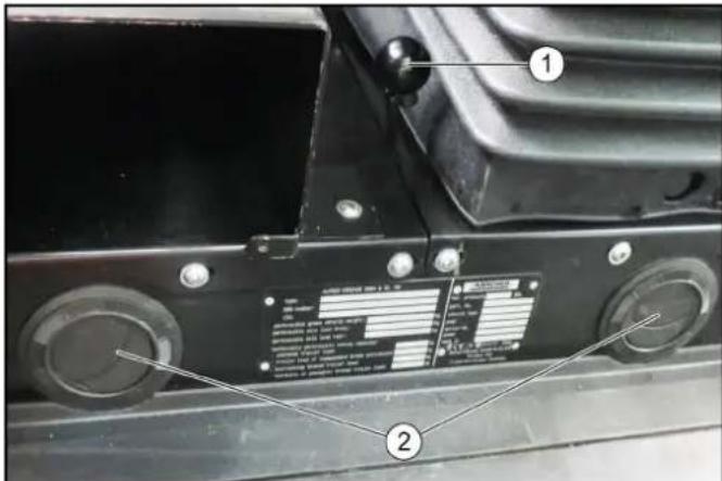
Interior filter
① Screws
②Cover
③Coarse filter
④Fine filter of filter class F8 (option)
The fresh air is sucked through a dust filter or fine dust filter at the side of the driver cabin.
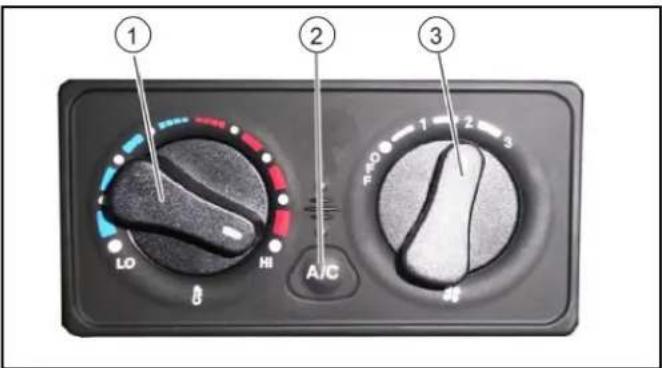
Air recirculation
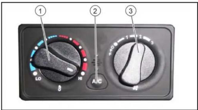
① Heating temperature control
②Air-conditioner controller (option)
③Air fan controller
The circulation air function ensures that a fogged windscreen clears more quickly when the air-conditioner or air blower is switched on. The cab air can also be warmed more quickly. Also useful in the case of unpleasant outdoor odours.
① Air recirculation lever
②Ventilation nozzles
Pull the air recirculation lever forwards.
ATTENTION
Only use this function for a limited period, since air is not exchanged from the outside with this setting.
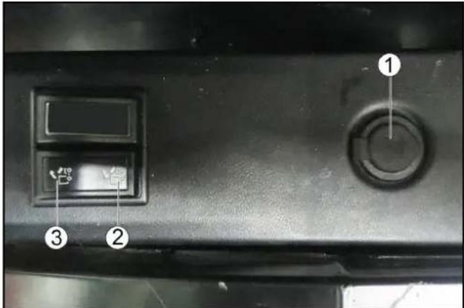
Waste container controls
The switch for emptying the waste container is located next to the driver's seat.
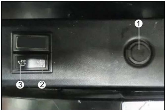
①Additional socket-outlet, 12 V
②Raise the waste container/attachment frame
③Lower the waste container/attachment frame
Spray controls
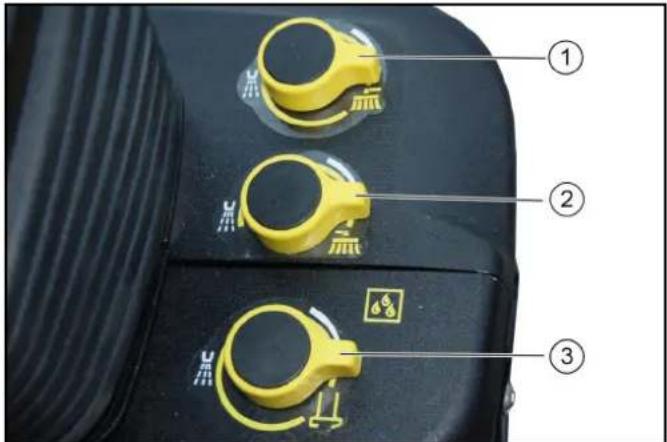
① Left side brush spray dosage knob
②Right side brush spray dosage knob
③Suction mouth spray dosage knob
-
Switch on the water pump (control panel).
-
Turn the corresponding dosage knob.
Note
Turning to the left increases the spray water volume. Turning to the right increases the spray water volume.
Switch panel
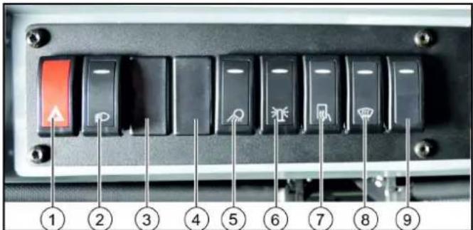
①Warning flasher system switch
②Lighting switch
Position 0: Driving light off (pressed down)
Position 1: Parking light on (middle position)
Position 2: Driving light on (pressed up)
③ Working light switch
④Rear fog lamp switch (option)
⑤Front working light switch
⑥Flashing beacon switch
⑦Switch for heatable outside mirror (option)
The heating switches off again automatically
⑧Heated windscreen switch
The heating switches off again automatically
⑨Seat heater switch
Note
The indicator in the switch lights up when it is switched on.
Ignition lock
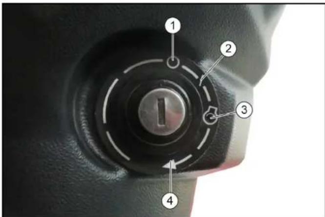
①Engine off
②Ignition on
③Preheating (automatic)
④ Start the engine
The ignition lock is located below the travel direction lever.
Steering wheel panel
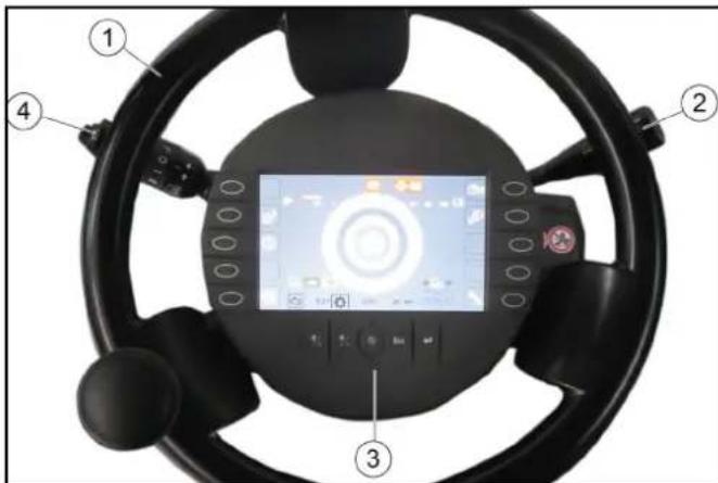
①Steering wheel
②Travel direction lever
③Display with function buttons
④Multi-function switch
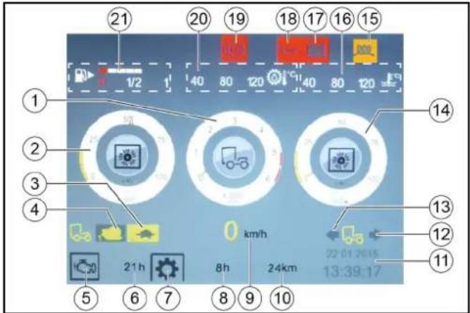
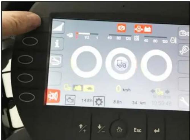
Display
The following indicators are shown on the display after switching on the ignition.
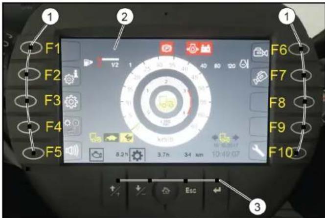
①Function buttons
②Display indicator in start/transport mode
③Setting buttons
The display changes when the corresponding function button is pressed. Pressing again or pressing the "Home" button returns you to the previous display.
The settings button is used for changing the settings.
| Function buttons |
| F1 Information such as the vehicle operating instructions can be stored hereIn working mode: Switch in the high-pressure cleaner (Option) |
| F2 Display date and time |
| F3 Settings |
| F4 | Bridging the seat contact switch, see chapter Operation with a bridged seat contact switch |
| F5 Reversing warning buzzer on/off |
| F6 Reversing camera on/off |
| F7 Suction mouth camera on/off |
| F8 Set Tempomat |
| F9 Resume Tempomat |
| F10 Service menu |
| Setting buttons | |
| + button Jumps one field up when making settings |
| - button Jumps one field down when making settings |
| "Home" button Navigates to the "Home" screen for the respective operating mode (Transport / Work) |
| Esc button Jumps one step back when making settings |
| "Return" button Completes a setting procedure |
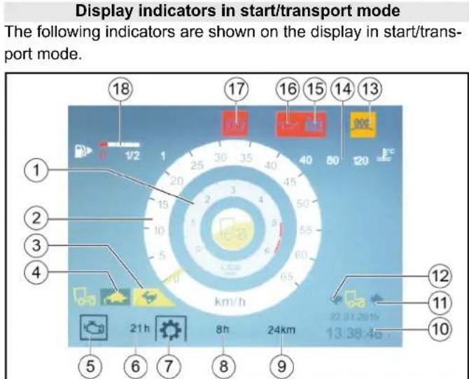
①Engine speed
②Travel speed
③Hare symbol (Fast mode indicator)
④Tortoise symbol (Slow mode indicator)
⑤Engine operating hours symbol
⑥Operating hours counter
⑦ Working hours symbol (no function)
⑧ Working hours meter
⑨Mileage
⑩Date and time
⑪Travel direction backwards
⑫Forwards direction of travel
⑬Preheating coil symbol
⑭Engine coolant temperature
⑮Battery charging monitor warning light
⑯Engine oil pressure warning light
⑰Parking brake warning light actuated
⑱Fuel level indicator
Symbols on the display
The following symbols and warning indicators can be shown on the display.
| Parking light |
| Driving light |
| High beam |
| Fog lamps |
| Hydraulic oil filter malfunction |
| Preheating active |
| Battery charge status warning |
| Malfunction |
| Hydraulic oil level warning |
| Fuel level warning |
| Floating position 1 |
| Floating position 2 |
| Floating position 1 and 2 |
| Driving direction indicator |
| Perform the regeneration process |
| Engine air filter malfunction |
 | Critical malfunction, switch off the engine |
 | Lower suction mouth |
 | Seat contact switch malfunction |
 | Engine coolant temperature warning |
 | Parking brake active |
 | Rear light indicator lamp flasher |
 | Engine oil pressure warning |
 | Hydraulic oil temperature too high warning |
 | Regeneration not possible |
 | High exhaust temperature |
 | Switch off the engine |
 | Engine malfunction |
 | Service required |
Working mode indicators
The following indicators are shown on the display when switching to Working mode (PTO).
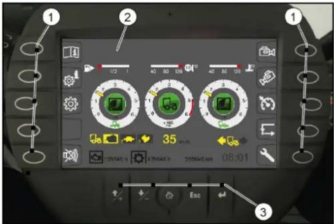
①Function buttons
②Working mode displays
③Setting buttons
The function and settings buttons have already been described previously.
Working mode displays
The following indicators are shown on the display when switching to Working mode (PTO).
①Engine speed
②Front attachment drive triggering level in %
③Tortoise symbol (Fast mode indicator)
④Snail symbol (Slow mode indicator)
⑤Engine operating hours symbol
⑥Operating hours counter
⑦ Working hours symbol (no function)
⑧ Working hours meter
⑨Working speed
⑩Mileage
⑪Date and time
⑫Travel direction backwards
⑬Forwards direction of travel
⑭Rear attachment drive triggering level in %
⑮Preheating coil symbol
⑯Engine coolant temperature
⑰Battery charging monitor warning light
⑱Engine oil pressure warning light
⑲Parking brake warning light actuated
⑳Hydraulic oil temperature
②1 Fuel level indicator
Depressurise the hydraulic system (pressure relief)
The hydraulic system must be depressurised before disconnecting the hydraulic hoses from the hydraulic connections.
- Unplug the signal plug for attachment device detection (front).
- Switch on the ignition (do not start the engine).
- Switch on the PTO work hydraulics (at the arm rest control panel).
- Press the function key F 10 on the display.
- Press function key F 6.
The rear hydraulic system is depressurised
- Press function key F1.
The front hydraulic system is depressurised
7. Disconnect the hydraulic hoses.
8. Remove the attachment device.
Note
Attachment is performed in reverse sequence.
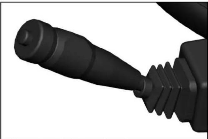
Multi-function switch
natural_image
Close-up of a black mechanical component with threaded shaft and threaded end (no visible text or symbols)
• Horns: Press the button on the end
- Flash to the right: Lever forwards
- Flash to the left: Lever backwards
- High beam: Press the lever down with the driving light switched on
- Flasher: Pull lever and release
- Turn the ring: Turn on the windscreen wiper
Turn forward - interval
Turn backwards - 1. Continuous wipe level, keep turning for 2nd level
- Press the ring: Wiping with washer water
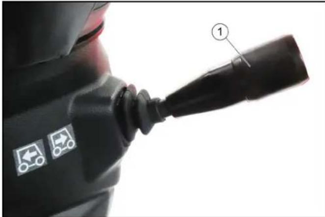
Travel direction selector switch
Select the travel direction using the travel direction selector switch.
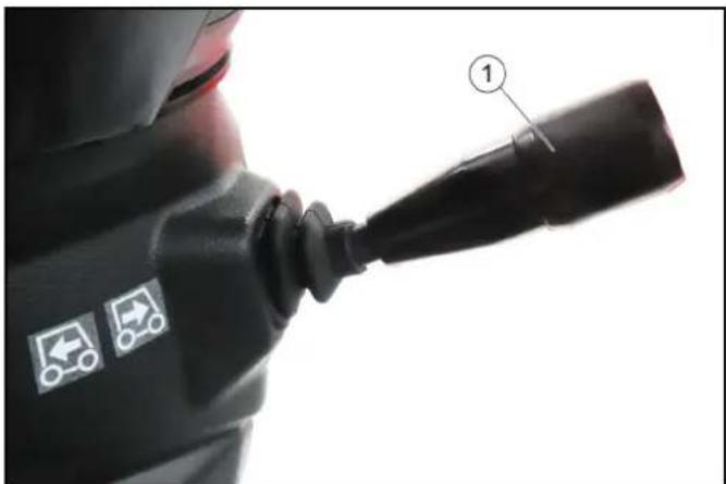
natural_image
Close-up of a person's shoulder joint with two vehicle icons and a numbered label (1), no readable text or symbols beyond icons.
①Travel direction selector switch
The following functions can be selected using the travel direction selector switch, the selected programs are shown on the display.
- Neutral position
The travel direction selector switch is in the middle
• Forwards direction of travel
Press the travel direction selector switch upwards and forwards
• Travel direction backwards
Press the travel direction selector switch upwards and pull backwards
- Switchover between the fast (Hare) and slow (Tortoise) operating programs
Press the travel direction selector switch to the end position (travel direction switch must first be in the neutral position).
Pedals
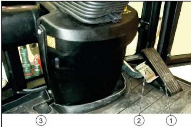
① Accelerator
②Brake pedal
③Brush contact pressure/brush speed pedal
Accelerator
ATTENTION
Other than in a normal motorcar, releasing the accelerator pedal abruptly reduces the speed.
The braking force applied when you release the accelerator pedal is weaker in higher gears and stronger in lower gears.
The braking force applied when you release the accelerator pedal in transport mode is significantly weaker than in working mode.
Pressing the accelerator pedal increases the engine speed.
The accelerator pedal is sprung. Releasing the accelerator pedal reduces the engine speed.
The hydrostatic drive brakes or stops the vehicle when the accelerator pedal is released.
Brake pedal
The brake pedal activates the braking system for the front wheels.
Parking brake
Parking brake for securing the parked vehicle.
Note
If the "Parking brake active" warning light in the display lights up then the parking brake is engaged.
Vacuum sweeper
① Sweeping mechanism
②Suction mouth
③ Waste container
The structure of the vacuum sweeper consists of a waste container, sweeping mechanism and suction mouth.
Accessories and options
Only accessories, spare parts and upgrade kits that are approved by the manufacturer may be used. To avoid risks, all repairs and installation of spare parts may only be carried out by the authorised customer service personnel. For information about accessories and spare parts, please visit www.kaercher.com.
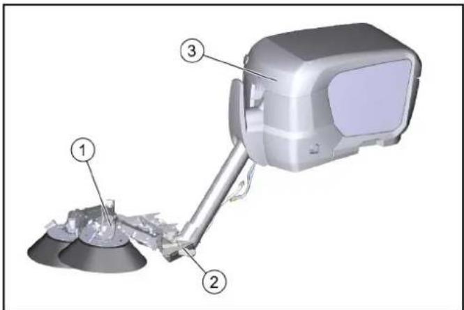
The following accessories and options can be purchased additionally and attached to the device:
Water circulation system / recycling mode
①Suction mouth
②Recycling water hose
③Suction hose
④ Waste container
In recycling mode, the suction hose is continuously cleaned by water from the waste container.
The water is filtered by a pipe filter in the waste container and then channelled through the recycling water hose to the suction mouth via a valve.
This recycling water is immediate sucked in again at the suction mouth and then channelled back to the waste container through the suction hose.
The suction hose is continuously cleaned.
Manual suction hose attachment kit
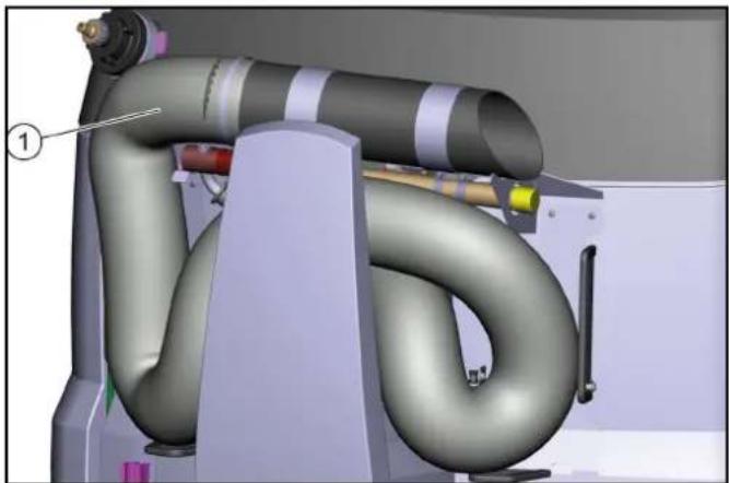
natural_image
3D mechanical assembly diagram showing internal components of a turbocharger or compressor (no text or symbols visible)
①Manual suction hose attachment kit
High-pressure cleaner, brush and dirt scraper attachment kit
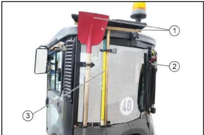
①Brush and shovel
②High pressure cleaner
③Dirt scraper
Note
When retrofitted, the brackets must be installed and also the side panel cutouts for holding the brush and shovel handles.
Drive light/direction indicator attachment kit
①Drive light/direction indicator attachment kit
These are switched on and off via a special switch in the ceiling control panel.
②Driving light/flasher
Suction mouth camera

natural_image
Close-up of a black rectangular electronic device with metallic pins and a central lens (no visible text or symbols)
The suction mouth camera is fastened at the sweeper system suction mouth.
Reversing camera

natural_image
Close-up of a black rectangular electronic device with a central lens and metallic connectors (no visible text or symbols)
The reversing camera is located at the rear of the vehicle.
△WARNING
The reversing camera is no substitute for an awareness of the surroundings
Always pay attention to the surroundings when reversing.
Ensure no persons, animals or objects are located in the manoeuvring range.
Radio

The optionally available radio is locate in the ceiling console.
See the manufacturer's operating instructions for operating the radio.
The seat contact switch can be bridged to allow using the work hydraulic system (PTO) when the driver's seat is not occupied. This allows e.g. the suction hose or high-pressure cleaner to be used when nobody is sitting on the driver's seat.
This function is only possible in working mode, see chapter Bridging the seat contact switch.
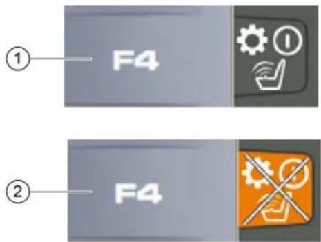
-
Apply the parking brake.
-
Press function key F4.
Note
The "Seat contact switch overridden" warning symbol appears on the display.
- Press function key F4 again to switch off the function.
The seat contact switch is now bridged and the PTO remains active.
Initial startup
△CAUTION
Read the operating instructions for attachments!
When using attachments or pulled devices and trailers prior to initial startup, read the corresponding operating instructions and follow them.
Pay attention to permissible loads, see chapter Technical data.
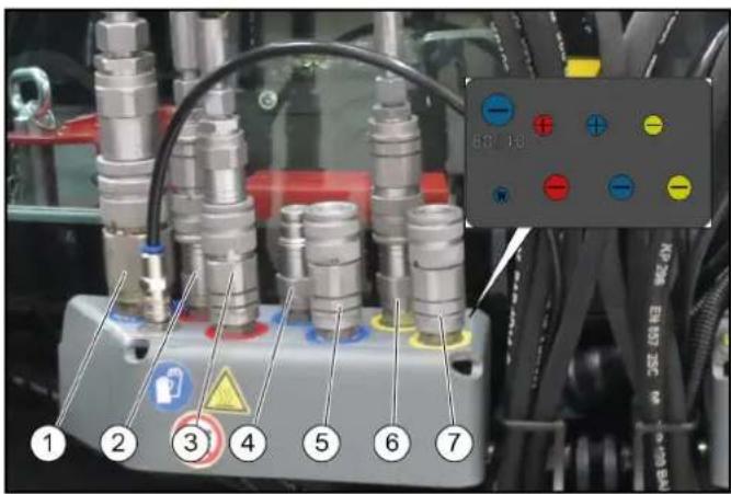
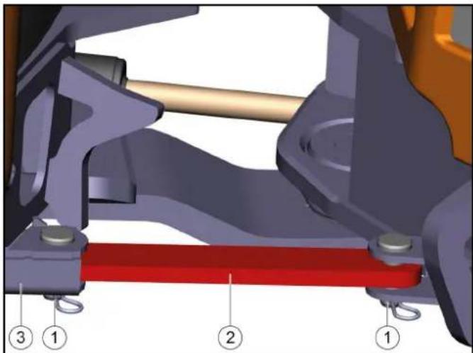
Release the transport lock at the articulated joint
natural_image
Mechanical assembly diagram showing a lever mechanism with numbered components (1, 2, 3), no readable text or symbols present.
①Pin with locking pin
②Transport lock
③Transport lock storage
- Pull out the locking pin.
- Pull out both bolts.
- Slide the transport lock into the storage.
- Insert the pins.
- Secure the pins with locking pins.
Switching on the main switch
①Main switch
②Battery disconnected
③Battery connected
- Put the main switch into the "battery connected" position.
Safety checks before startup
△DANGER
Risk of accident and injury due to faulty vehicle
Do not start up the vehicle if one point from the safety check is not fulfilled but rather repair the vehicle.
Note
Perform the recommended safety checks each time before using the vehicle.
Device carrier safety check
Check the following points before each startup:
- Release the transport lock, see chapter Release the transport lock at the articulated joint
- Check the cleanliness of the hydraulic connections
- Check the hydraulic lines for leaks
- Check the hydraulic oil level, see chapter Checking the hydraulic oil level and topping up the hydraulic oil
- Check the engine oil level, see chapter
- Check the coolant level, see chapter
- Check the coolant for sufficient antifreeze if a danger of frost exists
- Check the electrical cables for damage
- Check that all nuts and bolts are securely seated
- Check the vehicle, engine and radiator grille for damage
- Check the cleanliness of the engine air filter
- Check the cleanliness of the cab dust filter
- Check the fluid level in the windscreen washer reservoir, see chapter
14.Type pressures and tyre wear
In the vehicle
15.Ease of movement of the accelerator pedal
16.Are the working hydraulics (PTO) switched off?
17. With the ignition switched on: Do the charge indicator and oil pressure warning lights light up?
Start the engine and check the following:
18.Do the charge indicator and oil pressure warning lights go out?
19. Are the temperature indicator and fuel level indicator functioning?
20. Are the lighting system, travel direction indicator and flasher system functioning correctly?
Safety checks on the vacuum sweeper
Note
Perform this safety check in addition to the device carrier safety check.
Check the operational and traffic safety of the vehicle before driving.
- Fastening of the waste container.
- Check the hydraulic and electric connections to the device carrier.
- Check the spray water connections to the sweeping system and suction mouth.
- Check the recycling water connection to the suction mouth (option).
- Check the spray water filling level at the fresh water tank.
- Recycling water filling level in waste container (option).
- Check the sweeping system and brushes for entangled cords and tape.
- Check the connections at the sweeping system and suction mouth.
- Check the fastening of the sweeping system and suction mouth.
Setting the driver's seat
△DANGER
Danger of accident
Only adjust the driver's seat when the device is standing.
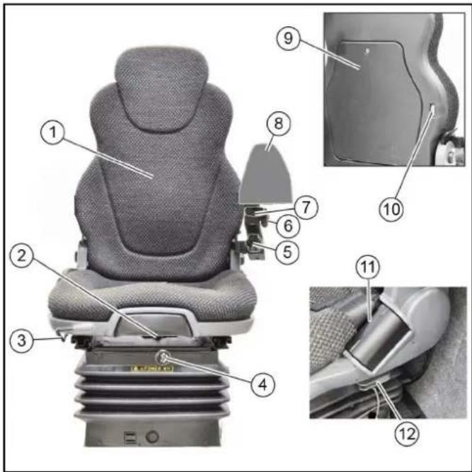
①Backrest with pole extension Pull out for height adjustment
②Backrest inclination adjustment
③ Horizontal adjustment - pull the lever upwards to adjust
④Compressor switch - for air-cushioned seat (option)
⑤Right arm rest height adjustment
⑥ Left arm rest side adjustment
⑦ Left arm rest length adjustment
⑧Arm rest control panel
⑨Document storage
⑩Lumbar support adjustment
⑪Seat belt
⑫Horizontal shock absorber
- Adjust the inclination, height and position of the left arm rest for operating the control panel.
Height adjustment with "air-suspended seat" option:
- Pump the seat all the way up with the compressor and then lower it 2 - 3 cm.
Note
The driver's seat is automatically damped.
Passenger seat
The passenger seat is horizontally adjustable, pull the lever upwards to adjust.
Setting the steering wheel position
△DANGER
Danger of accident
Only adjust the position of the steering wheel when the device is standing.
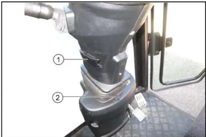
① Steering wheel height adjustment locking lever
② Steering wheel inclination adjustment lever
1. Pull and hold the inclination adjustment lever and set the steering wheel to the desired inclination.
2. Push in the lever.
3. Release the height adjustment locking lever and set the steering wheel to the desired height.
4. Lock the locking lever.
Refuelling
△DANGER
Risk of explosion
Do not refuel in confined spaces.
Do not smoke and avoid open flames.
Ensure that no fuel gets on hot surfaces.
- Switch off the ignition.
- Open the tank cap.
- Fill with fuel.
Only the fuel specified in the operating instructions may be used.
- Wipe of any spilt fuel and close the tank cap.
Refuelling with the fuel canister
Estimate the required amount of fuel in advance to avoid overflows.
Filling the water reservoir
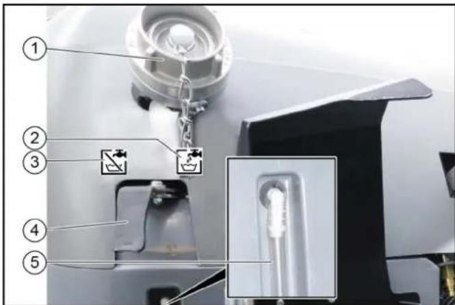
①Filling nozzle
②Symbol for the "Fill" lever position
③Symbol for the "Closed" lever position
④Switch lever
⑤Filling level display
- Open the cap on the filling nozzle.
- Switch lever in the "Fill" position.
- Fit a water supply hose onto the filling nozzle.
- Fill the water reservoir.
Note
To prevent back suction, the water hose must not be inserted into the water reservoir when filling.
- Close off the water inlet.
- Remove the water supply hose.
- Close the cap on the filling nozzle.
- Switch the switchover lever to the "Closed" position.
Filling the water reservoir for a water circulation system/recycling mode (option)
With a water circulation system (Recycling mode), water is directly filled into the waste container.
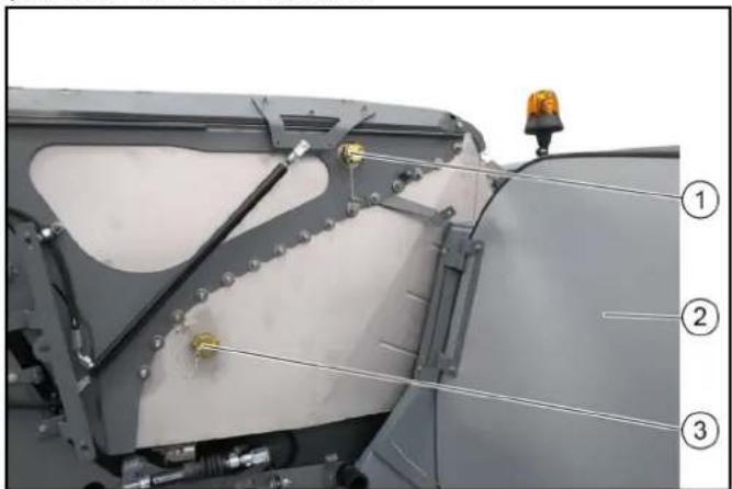
natural_image
Close-up of a mechanical component with labeled parts (1, 2, 3), no visible text or symbols beyond numbered annotations.
①Water filling connection (GEKA)
②Right-hand panel
③Water drain (fill height)
- Unlock the right-hand panel and pivot it outwards.
- Remove the lock from the water filling connection and water outlet.
- Connect the water hose to the water filling connection
- Fill the waste container with water (max. 100 litres) until water escapes from the open water drain.
- Reattach both locks.
- Close the panels
- Switch on recycling mode at the control panel.
Operation
△DANGER
Danger of crushing
Make sure that no persons are present in the vicinity of the articulated joint or vehicle during operation.
When using the vehicle for towing, make sure that no persons are located during operation between vehicle and trailer.
△CAUTION
Risk of burns
Only use the vehicle if all panels are attached.
ATTENTION
Risk of damage due to overheated hydraulic oil or overheated motor!
In case of excessive hydraulic oil temperature or an excessive coolant temperature, set the motor speed to idle mode (do not switch off the motor).
Perform the measures in the "Malfunctions" section
ATTENTION
Risk of damage due to missing lubrication
If the warning light for the oil pressure lights up during operation, immediately move the vehicle out of the danger zone, switch off the motor immediately and rectify the fault.
△CAUTION
Reduced stability due to attachments
Adjust the driving style.
During the first 50/100 operating hours (running-in period)
- Drive the first 100 hours of operation gently and avoid overloading.
- Replace the engine oil, engine oil filter and hydraulic oil filter after 50 operating hours (authorised Customer Service department only).
Parking brake
The parking brake requires hydraulic pressure to release. The brakes are automatically actuated when the engine is switched off.
The parking brake is also applied when the engine is running and the travel direction lever is in the NEUTRAL position.
Note
The "Parking brake applied" warning light in the multifunction display lights up when the parking brake is applied.
Setting the heating, ventilation and air-conditioner
①Air fan controller
②Air-conditioner controller (option)
③ Heating controller
- Adjust the ventilation, heating and air-conditioner (option) using the 3 controllers.
①Air recirculation lever
②Ventilation nozzles
2. Adjust the volume and direction of the airflow at the ventilation nozzles.
Drive mode
Start motor
The main switch must be switched on.
- Sit down on the driver seat and fasten the seat belt.
- Insert the ignition key into the ignition lock.
- Set the travel direction lever into central position (neutral position).
- Turn on the ignition.
Warning lights for charge control and motor oil pressure must be on.
- Start the motor.
Warning lights for charge control and motor oil pressure must go out; if not, switch off the motor and rectify the error.
- At ambient temperatures below 0 °C: Warm up the vehicle at a low motor speed until the "Hydraulic oil temperature too low" warning light goes out.
Selecting the travel direction
natural_image
Close-up of a black mechanical component with two directional icons and a numbered label (1), no readable text or symbols beyond icons.
①Travel direction selector switch
-
Press the travel direction selector switch towards the steering wheel and in the desired travel direction.
The travel direction is shown in the display.
-
Bring the travel direction selector switch into the middle position (neutral position).
The engine idles.
-
Press the travel direction selector switch to the end position.
-
Select the transport speed (between tortoise 20 km/h and hare 40 km/h).
The symbols are shown in the display.
- Regulate the travel speed using the accelerator pedal.
ATTENTION
The vehicle must be at a standstill and the travel direction selector switch in the neutral position before changing the travel speed.
Operating error
If the travel direction selector switch is in the forwards or reverse position when changing speed, the tortoise/hare symbol on the display will change but the travel speed will not switch over.
Driving
△WARNING
Risk of accident
Do not drive while the waste container is raised.
△CAUTION
Risk of accident
Do not let go of the accelerator pedal abruptly during driving. The vehicle will be braked when the accelerator pedal is released.
The vehicle will be decelerated to a lesser extent when the accelerator pedal is released in transport mode rather than in operating mode.
△CAUTION
Risk of damage
Make sure that the vehicle does not become stuck when driving over obstacles.
Drive over obstacles up to 150 mm slowly and carefully at an angle of 45^ .
Obstacles above 150 mm may only be driven over using a suitable ramp.
△CAUTION
Risk of accident
When driving on public roads for transport purposes (and not when cleaning of public roads), switch off the PTO and close the lowering choke for the front power lift.
- Switch off PTO.
- Carefully depress the accelerator pedal.
- Control the travel direction using the steering wheel.
Stopping
- Release the accelerator pedal.
The vehicle brakes automatically and comes to a standstill.
- For a stronger braking effect or in case of an emergency, actuate the brake pedal.
Tempomat
The Tempomat is only active in Working mode.
Activating Tempomat
1 Select the desired working speed using the accelerator.
2 Press function key F 8.
Tempomat is activated.
Deactivating Tempomat
1 Press the brake pedal or function key F 8.
Function key F 9 (Resume Tempomat) activates the previously set speed.
Parking the vehicle
- Stop the vehicle.
- Bring the travel direction lever into the neutral position (middle position).
Note
In this position, the parking brake is automatically actuated; the vehicle does not move.
- Lowe the front power lift.
If a sweeper is used:
- Raise the side brushes.
- Switching off the "eco" function
or
- Switch off the water pump.
- Wait 20 seconds.
- Switch off the suction fan.
- Raise the suction mouth.
- Switch off the PTO.
All sweeping functions are deactivated.
- Allow the engine to run in idle mode for 1 to 2 minutes.
- Switch off the ignition and remove the ignition key.
- Wait for 30 seconds to allow the engine control unit storage process to complete.
- Turn the main switch to position 0.
Sweeping mode
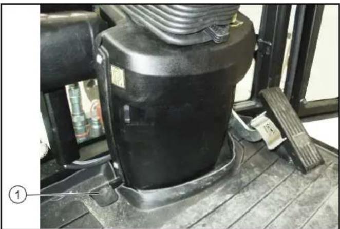
natural_image
Close-up of a black industrial machine component mounted on a wooden floor, with no visible text or symbols.
①Brush contact pressure pedal
Press the pedal briefly: Full brush contact pressure and increased brush speed for heavy soiling.
Hold the pedal pressed: Suction mouth remains lowered when reversing, vacuumed substances are also taken up when reversing.
Setting the sweeping parameters
(A) Button for setting the side brush speed
For individual extraction (option), left side brush speed button
(B) Button for setting the side brush speed
For individual extraction (option), right side brush speed button
(C) Button for setting the engine speed
Note
The suction power depends on the set engine speed.
• 1600 rpm Light waste
• 2200 rpm Normal soiling
• 2500 rpm Strong, heavy soiling
(D) Left and ride brush contact pressure button
For individual extraction (option), right side brush contact pressure button
(E) Left and ride brush contact pressure button
For individual extraction (option), left side brush contact pressure button
(F) Press the Save button to save set values or programs
(G) Rotary knob for changing values and selecting programs
- Switch on the PTO.
-
Press the Side brush speed button.
-
Use the rotary knob to select the desired side brush speed.
- Press the Save button.
The settings appear on the display.
The side brush speed has now been saved.
5. Press the Engine speed button.
5. Press the Engine speed button.
The settings appear on the display.
5. Press the Engine speed button.
The settings appear on the display.
5. Press the Engine speed button.
The settings appear on the display.
5. Press the Engine speed button.
The settings appear on the display.
5. Press the Engine speed button.
The settings appear on the display.
- Use the rotary knob to select the desired engine speed.
- Press the Save button.
The engine speed has now been saved.
- Press the Side brush contact pressure button.
The settings appear on the display.
- Use the rotary knob to select the desired contact pressure.
- Press the Save button.
The contact pressure is saved.
Sweeping with a 2-brush system
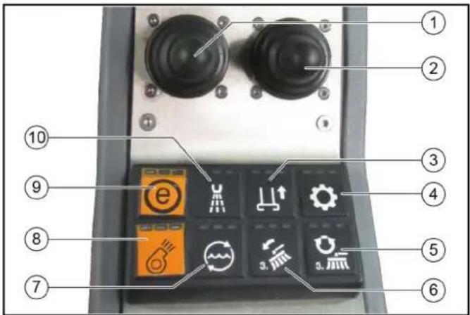
① Left joystick
2-brush system: Lower the brush arms and switch on the brushes
3-brush system (option): Lowering/raising the 3rd brush and switching the brush on/off
②Right joystick
With the optional 3-brush system: Lowering/raising the 2 rear brushes and switching the brushes on/off
Pivoting the brushes in and out
③ Raise/lower suction mouth
④ Hydraulic system on/off
⑤ With the optional 3-brush system: Brush reversal of the 3rd brush
⑥With the optional 3-brush system: Inclining/rolling the 2rd brush
Note
Operation with the right-hand joystick
⑦Water circulation function on/off
⑧Suction fan on/off
Note
The suction fan has an afterrun time of approx. 15 seconds after being switched off
⑨"eco" e function
Switches the complete work program on.
PTO, side brush, suction fan, fresh water, water circulation (recycling water)
⑩ Water pump on/off
Note
The indicators in the switches light when the switches are switched on.
- Start the engine, see chapter Start motor.
- Switch on the hydraulic system.
- Set the desired engine speed.
- Switch on lower suction mouth.
- Set the side brush speed.
- Switch on the suction fan.
- Move the left-hand joystick forwards.
The right and left brush arms are lowered and the brushes are switched on
Adjust the sweeping width.
- Move the right-hand joystick forwards.
The right side brush lowers and is switched on.
Adjust the sweeping width (optional).
When brushing dry, dusty waste:
- Switch on the water pump.
Optional: Switch on the water circulation function if necessary.
Emptying the waste container
△CAUTION
Risk of tilting
Only empty the waste container on a firm even subsurface.
Maintain the safety distance while emptying on dumps or ramps.
△CAUTION
Danger due to rolling away
Set the travel direction lever to neutral for emptying.
Apply parking brake.
△CAUTION
Danger of injury
Switch off the suction fan before emptying the waste container.
△CAUTION
Risk of injury
During the emptying process, persons and animals must not abide within the swivelling range of the waste container.
△CAUTION
Crush hazard
Never reach into the rod assembly for the emptying mechanism.
- Stop the vehicle.
-
Apply the parking brake.
-
Bring the travel direction lever into the neutral position (middle position).
-
Set the switch lever to the "Waste container" position.
-
Switch on the PTO.
-
Lift the right side brush and switch it off by moving the left joystick to the right and then pushing it back.
-
Lift the right side brush by moving the right joystick to the left and then pushing it back.
-
Switch off the water pump.
-
Wait 20 seconds.
-
Switch off the suction fan.
11.Actuate the toggle switch.
- Empty the waste container.
Note
Always raise the waste container fully to the end position.
Regeneration process for vehicles with a diesel particle filter (DPF)
The DPF collects soot particles that are burned off by increasing the emission temperature when the filter is clogged (regeneration).
The regeneration process runs either automatically during working mode or driving mode but can also be started manually if required.
The higher the speed when driving, or the greater the load, the less frequent the need for manual regeneration.
Start regeneration
△WARNING
Risk of burns
During the regeneration process, exhaust gases up to a temperature of 600^ C may be omitted.
Do not start the regeneration process in combustible areas.
Note
Only interrupt the regeneration process in the case of an emergency.
Note
If the regeneration indicator on the display lights up during operation then a regeneration process must be started.
Regeneration can be performed automatically or manually.
Work can continue during Automatic regeneration.
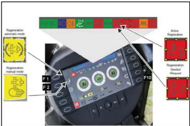
- For manual cleaning ("Parked regeneration"), stop at suitable location within 15 minutes.
Regeneration duration is approx. 30 minutes.
- Set the travel direction to the NEUTRAL position and do not press the accelerator pedal.
The driver's seat can be vacated during this period.
- To start the regeneration process, first press function key F 10 (lower right key), then press F 1 for Automatic or F 2 for Manual cleaning.
Note
The engine speed increases noticeably during both types of cleaning. When cleaning has finished the indicator lamp goes out and the engine speed decreases again.
Note
The regeneration instructions above should suffice in most cases and more detailed descriptions are provided in the section "Faults with display".
Automatic regeneration
△WARNING
Risk of burns
During the regeneration process, exhaust gases up to a temperature of 600^ C may be omitted.
Do not start the regeneration process in combustible areas.
Note
Work can continue during Automatic regeneration.
The automatic regeneration can be postponed in certain situations.
1.
Manual regeneration
⚠ WARNING
Risk of burns
During the regeneration process, exhaust gases up to a temperature of 600^ C may be omitted.
Do not start the regeneration process in combustible areas.
△CAUTION
Risk of burns from hot exhaust gases
Keep people, animals and flammable objects away from the regeneration area.
Note
Only interrupt the regeneration process in the case of an emergency.
Manual regeneration is not possible at less than 50 hours.
The average duration of the burning procedure during manual regeneration is approximately 20 minutes.
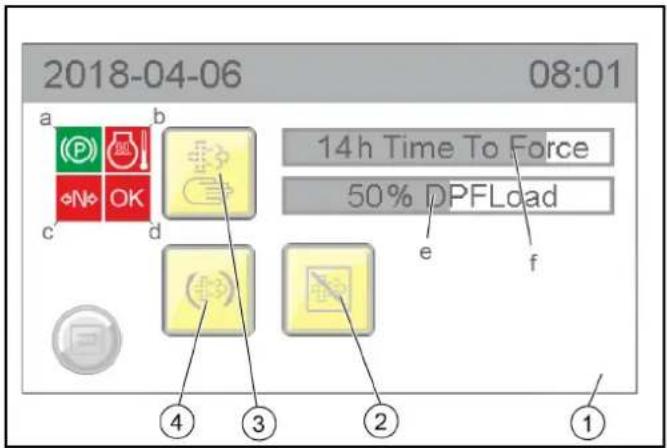
①Manual regeneration display
a) Parking brake display
b) Engine temperature display
c) Driving mode display
d) OK display
e) Particle filter % fill degree display
f) Display of the hours remaining until manual cleaning can be started
②Postponing automatic cleaning
③Activating manual cleaning
④Activating automatic cleaning
- Manual regeneration can only be started when all 4 characteristics are green:
a The parking brake is activated
b The engine temperature has exceeded a particular limit value
c The machine is in driving mode N (neutral)
d OK then lights up green and the manual burning procedure can be started
Winter use
Frost protection
- Ensure there is enough antifreeze in the coolant.
Sweeping system
During winter use, the sweeping system and suction mouth must be disassembled and placed into storage.
Working with the high-pressure cleaner (ex-factory option)
Intended use
Use the high-pressure cleaner only for the following activities:
- Cleaning with the high-pressure jet without detergent (e.g. façades, park seats, garden paths).
- Only operate the high-pressure cleaner with the flat jet nozzle provided.
- This high-pressure cleaner is intended and tested for the exclusive use with the sweeper vacuum MC 130.
Pressure relief valve
When the water quantity is reduced via the pressure/quantity control on the trigger gun, the overflow valve opens and part of the water flows back to the suction side of the pump.
Safety valve
The safety valve opens when the permissible operating pressure is exceeded and the water flows back to the suction side of the pump.
Device elements
①Trigger gun
②Pressure and quantity regulation
③Spray lance
④High-pressure hose connection
⑤ Nozzle holder
⑥High-pressure hose storage compartment
⑦High-pressure hose
⑧Fastening high-pressure hose
⑨Fastening trigger gun
⑩Fastening trigger gun
⑪ Trigger gun lever
①Water inlet from water reservoir
②Stop cock
③High-pressure cleaner hydraulic connection
④Water inlet for high-pressure pump
Connection to a drinking water line
△WARNING
Return flow of dirty water into the drinking water network Health risk
Observe the regulations of your water supply company.
According to applicable regulations, the device must never be used with the drinking water network without a system separator.
Use a system separator from KÄRCHER or a system separator as per EN 12729 Type BA. Water that has flowed through a system separator is classified as undrinkable. Always connect the system separator to the water supply and never directly to the water connection on the device.
Operation
Before initial startup
⚠ WARNING
Risk of injury from high-pressure jet
Do not direct the high-pressure jet at persons, animals, live electrical equipment or at the device itself.
Protect the device high-pressure cleaner frost.
ATTENTION
Environmental pollution through oil
Clean engines only at locations having an appropriate oil separator.
Note
Only nozzles of the sizes listed in the technical data may be used. If you have not already done so:
-
Connect the high-pressure hose and spray lance.
-
Connect the water supply hose and open the stop cock of the water inlet.
Operation
Note
The high-pressure cleaner may be operated only at an engine speed of 1600 rpm and only in work mode.
- Check the water filling level and fill the water reservoir of the MC 130 if necessary.
- Open the stop cock of the water inlet.
- Put travel direction lever in the NEUTRAL position - centre position and start the motor.
- Remove the trigger gun and high-pressure hose from storage.
- Switch on the PTO work hydraulics.
- Press F1 function key on the display and switch on the high-pressure cleaner.
Engine speed automatically increases to 1600 rpm.
A "high pressure" symbol appears in the display.
①Additional socket-outlet, 12 V
② Raise the waste container/attachment frame
③Lower the waste container/attachment frame
-
Switch on the high-pressure cleaner via the button on the display.
-
Unlock the trigger gun.
- Pull the trigger on the trigger gun and commence cleaning.
Note
For first use or when the water reservoir is empty, the high-pressure cleaner must be vented:
- Operate the high-pressure cleaner without the nozzle until there is no more air in the system.
Shutting down
- Close the trigger gun.
- Switch off the high-pressure cleaner with the switch on the right of the driver's seat.
- Switch off the work hydraulics.
- Actuate the trigger gun until the device is depressurised.
- Actuate the safety lever of the trigger gun to prevent the gun trigger from being unintentionally triggered.
- Fasten and secure the trigger gun with spray lance and high-pressure hose in storage.
Note
If the high-pressure cleaner is not needed, for example during winter operation (spreading salt and other work):
- Blow out the system with compressed air - see chapter Frost protection.
- Remove the high-pressure gun with spray lance and high-pressure hose from the device.
- Take off the device cover (3 quick fasteners) and close the high-pressure output with the protective part intended for it.
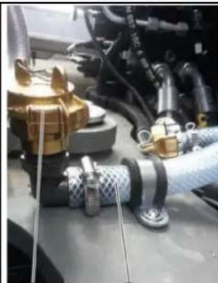
natural_image
Close-up of automotive engine components including hoses, hoses, and a car (no visible text or symbols)
①
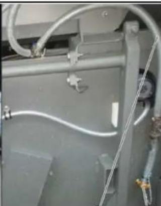
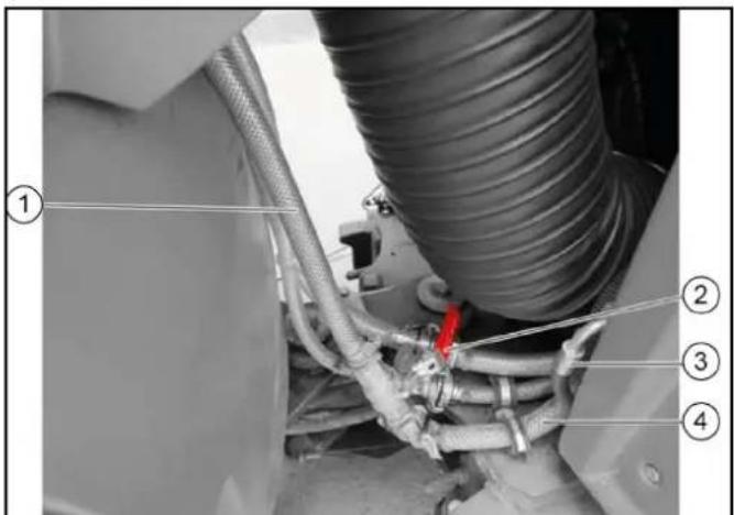
natural_image
Close-up of industrial piping and valves with coiled white cables (no visible text or symbols)
②
3
4
①Lock
②Water inlet for high-pressure pump
③Water inlet from water reservoir
④Fixing the water supply hose
10.Disconnect the water inlet at the GEKA connection.
-
Close the water inlet for the high-pressure pump.
-
Fix (store) the water supply hose of the water reservoir under the waste container.
Care and service
Each time before use
-
Check all hydraulic hoses and connections for leaks.
-
Check the high-pressure hose for damage (danger of bursting).
Immediately replace a damaged high-pressure hose.
- Check the device (pump) for leaks.
3 drops of water per minute are permissible and can leak out of the bottom of the appliance. Contact Customer Service in the case of more serious leaks.
Weekly
Note
To read the oil level or clean the water screen, remove the device cover (3 quick fasteners).
-
Read the oil level when the device is on a flat surface. The oil level must be in the middle of the sight glass.
Contact Customer Service immediately if the oil is milky (water in oil).
-
Clean the sieve in the water connection.
-
Depressurise the device.
-
Unscrew the cover with filter.
-
Clean the filter with clean water or compressed air.
Assemble in the reverse order.
Annually or after 500 operating hours
- Changing oil.
For oil quantity and type, see Technical data.
- Have the oil changed by Customer Service.
Frost protection
ATTENTION
Danger of frost
Incompletely emptied devices can be destroyed by frost.
Completely empty the device and accessories.
Protect the device from frost.
- Store the device in a frost-protected place.
Note
If frost-free storage is not possible:
-
Close off the water inlet.
-
Allow the device for run for a maximum of 1 minute until the pump and lines are empty.
-
Blow the high-pressure pump, supply hose, water filter and high-pressure hose out with compressed air.
Troubleshooting guide
△DANGER
Risk of injury due to inadvertently starting up device and also due to electric shock.
Switch off the device and remove the ignition key before performing any work.
Have electrical components checked and repaired by the authorised Customer Service.
In case of any malfunctions not mentioned in this chapter, contact the authorised Customer Service when in doubt or when you have been explicitly advised to do so.
Device not running
- Switch on the work hydraulics and high-pressure switch.
Device does not reach required pressure
-
Fill the water reservoir.
-
Clean the water inlet sieve, check the water supply.
-
Check/replace the high-pressure nozzle.
Pump leaking
Up to 3 drops of water per minute are permissible.
- In case of more serious leaks, have the device checked by Customer Service.
Pump knocking
- Check the water supply line for leaks.
● Vent the device, see section "Venting the device".
- Contact Customer Service if necessary.
Technical data
Hydraulic connection
| Supply from the hydraulic system of the MC 130 |
Water connection
| Water supply from the water reservoir of the MC 130 |
| Input temperature (max.) °C 60 |
Performance data
| Working pressure MPa 7-15 | | |
| Nozzle size 036 | | |
| Max. operating pressure MPa 19 | | |
| Flow rate l/min 10 | | |
| Recoil force of the trigger gun. (max.) N | 30 | |
Determined values in acc. with EN 60335-2-79
| Sound pressure level L_pA | dB(A) | 75 |
| K uncertainty _pA | dB(A) | 3 |
| Sound power level L_WA + K uncertainty_WA | dB(A) | 97 |
| Hand-arm vibration value | m/s ^2 | 1.6 |
| K uncertainty | m/s ^2 | 0.7 |
Operating materials
| Oil volume | 1 | 0.4 |
| Oil type | | SAE 15W-40 |
Dimensions and weights
Installation declaration
We hereby declare the technical documents according to EC Directive 2006/42/EC (+2009/127/EC) Annex VII Part B have been created for the incomplete machine described below and that this conforms to the following points of the directive:
Annex I Points 1.1, 1.2, 1.3, 1.4, 1.5, 1.6 and 1.7. I Point 1.1,
This declaration is invalidated by any changes made to the incomplete machine that are not approved by us.
Product: Attachment kit
High-pressure cleaner
Type: 2.851-952.7
Harmonised standards used, based on:
EN 60335-2-79
Authorities can request the relevant documentation for the incomplete machine from the documentation supervisor. Documents are provided via email.
Before commissioning or installation of the incomplete machine, it must be ensured that the complete machine into which the incomplete machine is installed conforms to the EC Machinery Directive 2006/42/EC (+2009/127/EC).
Please refer to the EC Declaration of Conformity for the machine for more information on this.
The signatories act on behalf of and with the authority of the company management.

H. Jenner
Chairman of the Board of Management
Documentation supervisör:
S. Reiser
Alfred Kärcher SE & Co. KG
Alfred-Kärcher-Str. 28 - 40
71364 Winnenden (Germany)
Ph.: +49 7195 14-0
Fax: +49 7195 14-2212
Winnenden, 2017/07/18

S. Reiser
Director Regulatory Affairs & Certification
Working with the manual suction hose (ex-factory option)
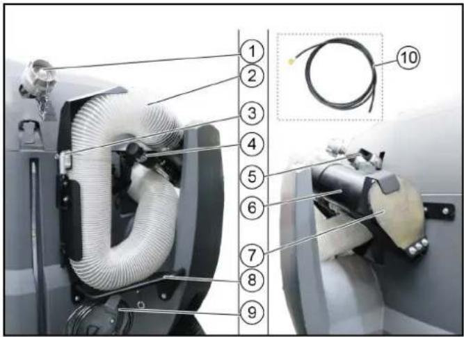
①Filling nozzle, water reservoir
②Suction hose (125 mm)
③Lock
④Handle (adjustable)
⑤Switch lever
Pulled out: Vacuuming with the suction hose
Pressed in: Work in sweeping mode
⑥Manual suction pipe
⑦Cover
⑧Suction hose bracket
⑨Water hose stowage compartment
⑩Water hose
Working with the manual suction hose
- Remove the manual suction hose from the stowage compartment.
- As necessary:
Connected the water hose provided and open the stop cock lever on the handle.
Close the dosing knobs in the cabin to prevent the emission of spray water for the suction mouth and sweeper jets, otherwise there will not be enough spray water for the manual suction hose.
- Pull out the switch lever into the "Vacuum with suction hose" position.
Vacuuming with the manual suction hose
- Start the motor.
- Switch on the PTO (at the arm rest control panel).
- Switch on the blower.
- As necessary: Switch on the water pump at the control panel.
- Select the engine speed.
Note
The suction performance depends on the engine speed selected. 1600 rpm - for light waste
2200 rpm - for normal waste
2500 rpm - for strong, heavy waste
6. Hold the suction pipe by the handle (adjustable) and begin vacuuming.
Storage of the manual suction hose
- Set the engine speed to 2200 rpm for installing the manual suction hose.
- When using the water hose: Switch off the water pump, disconnect the water hose and stop appropriately.
- Insert the suction pipe with handle, press against the cover and fasten in position.
Note
The vacuum pulls the suction pipe against the cover and the suction hose contracts. This is necessary to allow it to be stowed in the bracket.
- Press the rest of the suction hose into the bracket and press the flap closed until the latch engages.
- Switch off the blower.
- Press in the switch lever into the "Work in sweeping mode" position.
Attachments
Note
Please read the attachment operating instructions before fitting an attachment.
Attachments are optional and can be fitted to the front power lift (see chapter Front power lift (option)) or to the front or rear mounting frames.
⚠️DANGER
Danger due to change to vehicle's centre of gravity and to driving characteristics. When transporting fluids, sloshing motion may occur, which will then rock the vehicle.
In the case of modifications, particularly when converting from winter to summer use and in the case of changes to load conditions, the driver must be prepared for the change in driving characteristics.
△WARNING
Risk of crushing when attaching attachments
Do not reach between the front power lift and the attachment.
△CAUTION
Risk of burns from hot hydraulic couplings
Wear protective gloves when disconnecting the hydraulic couplings.
ATTENTION
Wear suitable protective clothing, safety gloves and gloves when installing and removing attachments. This also applies during usage and application.
Please contact your responsible dealer before fitting attachments that are not specifically intended for this vehicle. Your dealer will check if installation and use of these attachments is permitted on your vehicle. This is important for the safety of the driver and the vehicle and also for any warranty claims.
Attachments that endanger the safety or stability of the vehicle may not be used.
Coupling attachments to the vehicle
ATTENTION
Risk of damage
Keep hydraulic connections clean.
Clean the plug and coupling with a lint-free cloth before use.
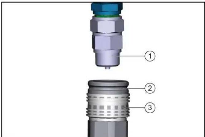
①Coupling connector
②Coupling sleeve
③Ring
- Pull the ring of the coupling sleeve downwards and hold.
- Press the coupling connector of the attachment hydraulic hose into the coupling sleeve.
- Release the coupling ring. Check that it is securely engaged.
- To decouple, pull the ring downwards, hold it and pull out the hydraulic hose.
Tow bar
Note
For permissible support load and trailer load, see chapter Technical data.
Checking adjusting the attachment locking mechanism
The locking mechanism secures the attachment devices (e.g. sweeper system, front power lift).
△CAUTION
Danger of accident
Check the locking mechanism for correct adjustment with each attachment.
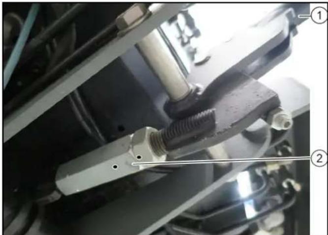
natural_image
Close-up of mechanical components with no visible text or symbols
①Locking lever
②Clamping nut
- Press the locking lever downwards.
The lock is engaged beyond the dead point.
- Adjust the lock via the clamping nut.
Ballasting the vehicle
Note
The front axle of the vehicle must always be loaded with at least 30% of the net weight of the vehicle, and the rear axle must always be loaded with at least 30% of the net weight of the vehicle. Before purchasing the attachment, check that these requirements are met by weighing the vehicle-attachment combination. The following data is required for determining the total weight, the axle loads, the tyre loading capacity and the required minimum ballast:
• All weights in kg (weigh the vehicle if necessary)
• All dimensions in meters (m)
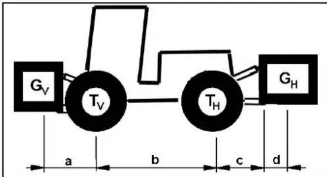
| TL (kg) = Net weight of the vehicle * | |
| TV (kg) = Front axle load of the empty vehicle * | |
| TH (kg) = Rear axle load of the empty vehicle * | |
| GH (kg) = Total weight rear attachment / rear ballast ** | |
| GV | (kg) = Total weight of front attachment / front ballast | ** |
| a | (m) | = | Distance between front attachment (front ballast) centre of gravity and middle of front axle, max. = 0.86 m | ** *** |
| b | (m) | = | * wheelbase of the vehicle | *** |
| c | (m) | = | 0.56 | |
| d | (m) | = | distance between the centre of the equipment-side attachment point and the centre of gravity of the rear attachment / rear ballast | ** *** |
* See chapter "Technical data"
** See operating instructions of the attachment
*** Measure
Calculation of the minimum front ballast for rear-mounted attachments
$$
G _ {V \min} = \frac {G _ {H} \times (c + d) - T _ {V} \times b + 0 , 2 \times T _ {L} \times b}{a + b}
$$
- Enter the result into the table.
Calculation of the minimum rear ballast for front-mounted attachments
See the manufacturer's specifications for the value "x" or use a value of x = 0.45 if no specifications are available.
$$
G _ {H \min} = \frac {G _ {V} \times a - T _ {H} \times b + x \times T _ {L} \times b}{b + c + d}
$$
- Enter the result into the table.
Calculation of the actual front axle load
$$
T _ {V t a t} = \frac {G _ {V} \times (a + b) + T _ {V} \times b - G _ {H} \times (c + d)}{b}
$$
- If the necessary minimum front ballast weight (GV min) is not reached with the front attachment (GV) then the weight of the front attachment must be increased to the minimum front ballast weight.
- Enter the actual calculated permissible front axle load and the permissible front axle load specified in the work machine operating instructions into the table.
Calculation of the actual total weight
$$
G _ {t a t} = G _ {V} + T _ {L} + G _ {H}
$$
- If the necessary minimum rear ballast weight (GH min) is not reached with the rear attachment (GH), then the weight of the rear attachment must be increased to the minimum rear ballast weight.
Calculation of the actual rear axle load
$$
T _ {H t a t} = G _ {t a t} - T _ {V t a t}
$$
- Enter the result into the table.
Waste container
Attaching the waste container
△DANGER
Risk of crushing when lowering/raising the waste container
Maintain sufficient clearance to the waste container and the rollers on the parking supports.
Maintain sufficient clearance to hazard zone and stop raising/lowering immediately when a person enters the hazard zone.
ATTENTION
Risk of injury and damage
The dirt receptacle and fresh water tank are empty.
Remove the waste container only on a level and smooth surface.
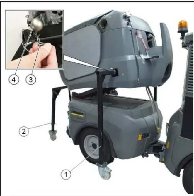
①Front parking support
②Rear parking support
③ Lever for securing the parking supports
④Retaining clip
- The waste container must be secured on the parking supports for installation.
- Set the switchover valve to the attachment frame position.
- Drive the rear of the vehicle carefully under the waste container.
- Raise the attachment frame slowly until under the waste container.
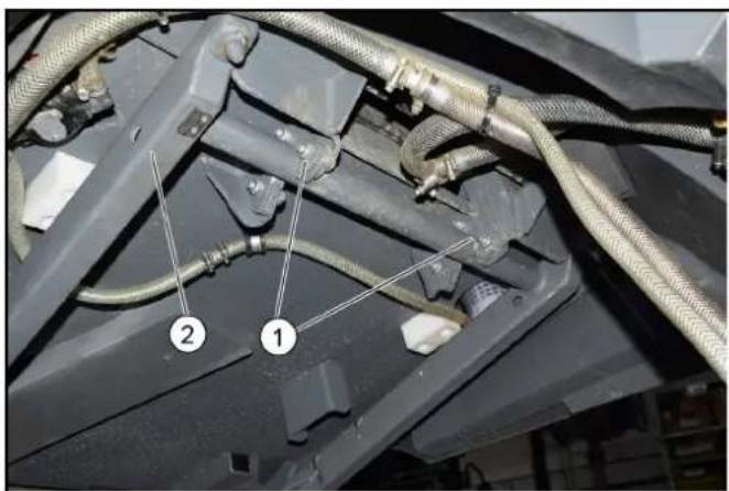
① Hooks
②Attachment frame
5. Hook the waste container onto the attachment frame using the retaining hooks.
- Continue raising the attachment frame until the load on the front parking supports is relieved.
a Lift the attachment frame only until the rollers of the front parking supports are approx. 20 mm in the air.
- Pull out the front parking supports. For this, pull the retainer to unlock and then press the lever.
- Completely lower the attachment frame together with the waste container.
- Pull out the rear parking supports. For this, pull the retainer to unlock and then press the lever.
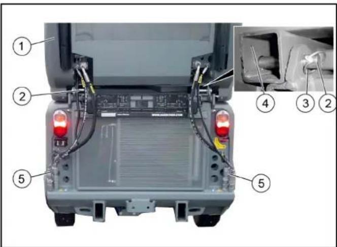
① Waste container
②Retaining pins
③Locking pin
④Frame
⑤Hydraulic connection
-
Push the retaining pin the of waste container in and secure with the locking pin.
-
Connect electrical and hydraulic connections.
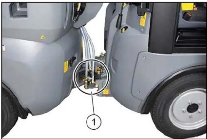
natural_image
Close-up of a gray industrial vehicle's side view showing internal components and a numbered annotation (1), no readable text or symbols present.
①Water connections
- Turn the steering wheel all the way to the right to provide better access to the connections on the articulated joint.
- Connect the water recycling hose.
- Connect the fresh water hose.
- Connect the high-pressure cleaner hose (optional).
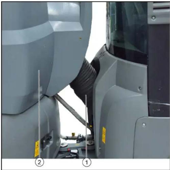
natural_image
Close-up of industrial machinery components with visible wiring and safety markings (no readable text or symbols)
①Suction hose
② Waste container
- Install the suction hose between the waste container and suction mouth.
Removing the waste container
△DANGER
Risk of crushing when lowering/raising the waste container Maintain sufficient clearance to the waste container and the rollers on the parking supports.
Maintain sufficient clearance to hazard zone and stop raising/ lowering immediately when a person enters the hazard zone.
ATTENTION
Risk of injury and damage
Empty the waste container and water reservoir before removing Set the waste container down only on a level and smooth surface.

natural_image
Close-up of a mechanical assembly with visible components and numbered labels (no readable text or symbols)
①Suction hose
② Waste container
-
Turn the steering wheel all the way to the right to provide better access to the articulated joint.
-
Disconnect and remove the suction hose from the waste container.
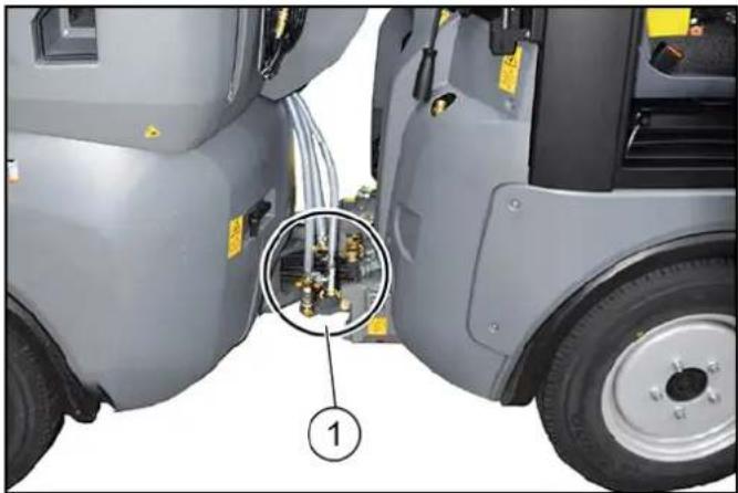
natural_image
Close-up of a gray industrial vehicle showing internal components and a numbered annotation (1), no readable text or symbols present.
①Water connections
- Disconnect the hoses for water recycling, fresh water and the high-pressure cleaner (optional).
- Steer the vehicle straight ahead.
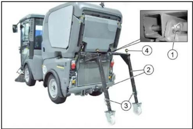
①Retaining pin for waste container with locking pin
②Rear parking supports
③Height adjustment with bolts and retaining clips
④ Safety lever with retaining clips
- Open the locking pin for the waste container from the retaining pin and remove it.
- Pull out the retaining pin.
- Adjust the rear parking supports to an appropriate height and secure in this position.
a The corresponding height depends on the tyre type and the tyre pressure.
- Push in the rear parking supports all the way to the end stops and secure in this position. To do this, press the safety lever down and push in the supports as far as they will go. Then secure the safety lever with the retaining clip.
- Depressurise the hydraulic system, see chapter.
- Disconnect the electrical and hydraulic connections from the waste container.
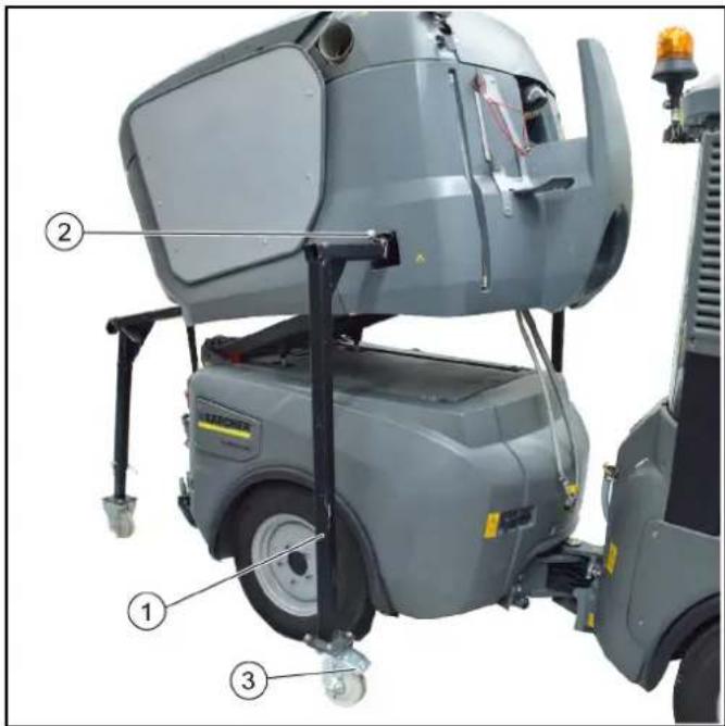
①Front parking support
② Safety lever with retaining clips
③Brakes
- Set the switchover valve to the tilting attachment frame position. See chapter.
- Raise the attachment frame with waste container.
- Push in the front parking supports as far as they will go and secure them. To do this, press the safety lever down and push in the supports as far as they will go. Then secure the safety lever with the retaining clip.
- Lower the attachment frame.
- Actuate the roller brakes on the front parking supports.
Note
The waste container now stands free on the parking supports.
- Drive the rear of the vehicle carefully out from under the waste container.
Sweeping system
Removing the sweeping system
A changing carriage is required for attaching/removing the sweeper system.
Note
Optional accessory, order no. 2.852-065.0.
- Stop the vehicle on level, solid ground and secure it against rolling away.
- Raise the side brushes and extend both side brushes outwards.
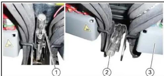
①Brush system unlocked lever position
②Brush system locked lever position
③ Vehicle front
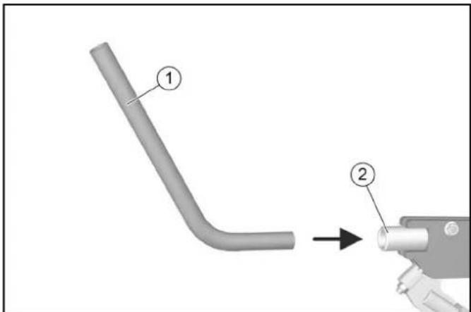
(1)Rod
(2)Locking lever
- Unlock the sweeping system by inserting the rod and pulling the locking lever upwards.
The rod needed for this is clamped in a holder between the driver's seat and passenger seat.
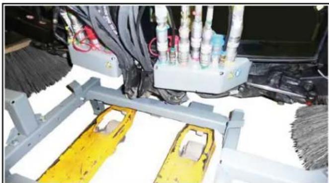
natural_image
Industrial robotic arm with white plastic components and yellow safety barriers, no visible text or symbols
- Use the lift truck to move the changing carriage centrally inwards as far as it will go.
Move the last distance (centring process) faster.
Note
Risk of damage! Watch out for cables and hoses.
- Raise the lift truck until the changing carriage makes contact with the sweeper system.
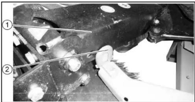
①Side brush arm
②End stop
- Retract both side brush arms.
- Check the side brush arms for correct seating.

natural_image
Mechanical vehicle chassis with two large tires mounted on a yellow support structure (no visible text or symbols)
- Depressurise the hydraulic system. See chapter Depressurise the hydraulic system (pressure relief).
- Set the ignition to position 1 in working mode (do not start the engine).
The brushes lower and the hydraulic system depressurises.
10.Disconnect all connections and joints.
- Remove the suction hose between the waste container and suction mouth.
- Disconnect the (thick) water hose.
13.Move the sweeper system out using the lift truck.
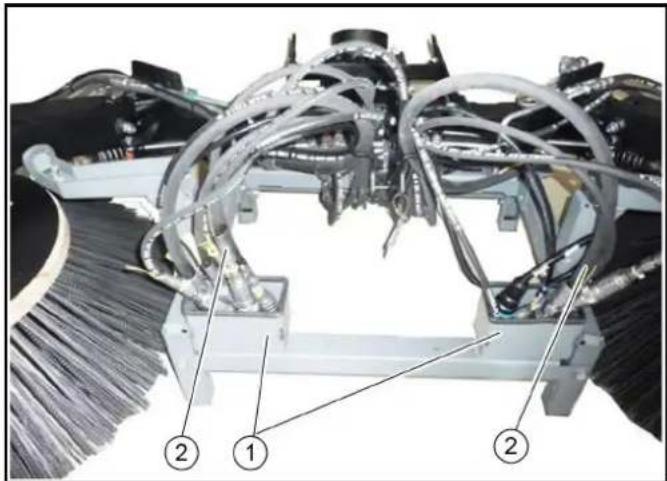
①Storage box
②Cables and hoses
14. Place the cables and hoses in the storage boxes.
15. Park the sweeper system in a safe place.
16. Extend the lift truck.
Installing the sweeping system
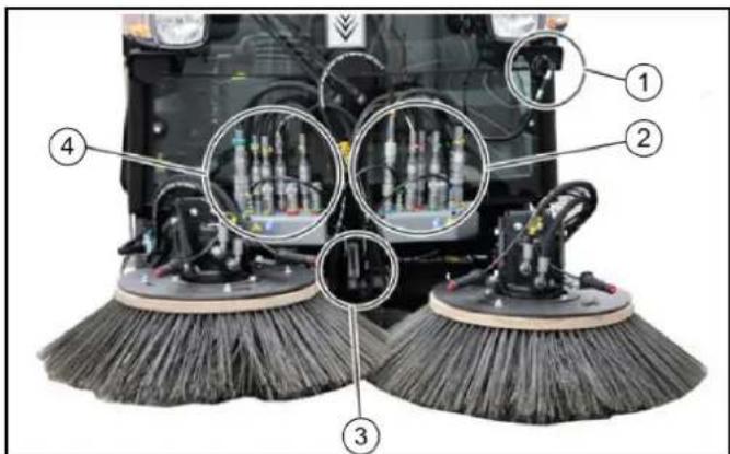
①Signal plug for attachment device detection
② Left side brush connections (hydraulics and water)
③Sweeping system lock
④Right side brush connections (hydraulics and water)
-
Stop the vehicle on level, solid ground and secure it against rolling away.
-
Attach the sweeper system to the vehicle in the reverse sequence.
- Lock the sweeper system (lever down).
- Check the locking, see chapter Checking adjusting the attachment locking mechanism.
- Depressurise the hydraulic system. See chapter Depressurise the hydraulic system (pressure relief).
- Connect the hydraulic hoses to the couplings.
Front power lift (option)
Various different attachment devices can be attached to the front power lifter using a 3-point mounting.
A changing carriage is required for attaching/removing the front power lift.
Note
Optional accessory, order no. 2.852-067.0.
Installing the front power lift
- Stop the vehicle on level, solid ground and secure it against rolling away.
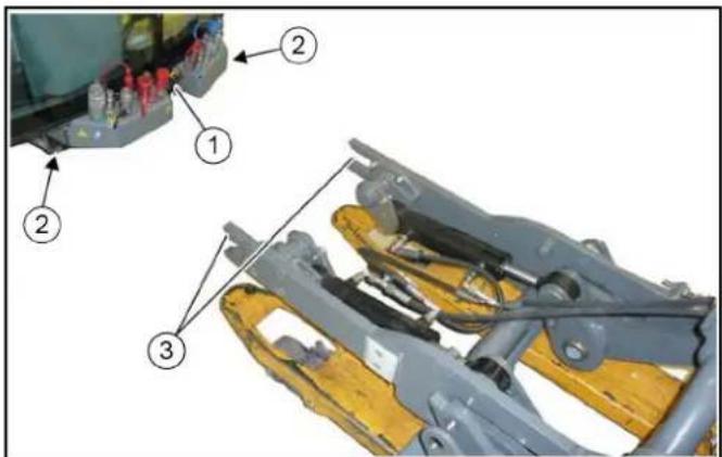
①Locking lever
② Vehicle mounting frame
③Front power lift mounting
2. Move the locking lever upwards.
3. Use the lift truck to position the front power lift centrally in front of the vehicle.
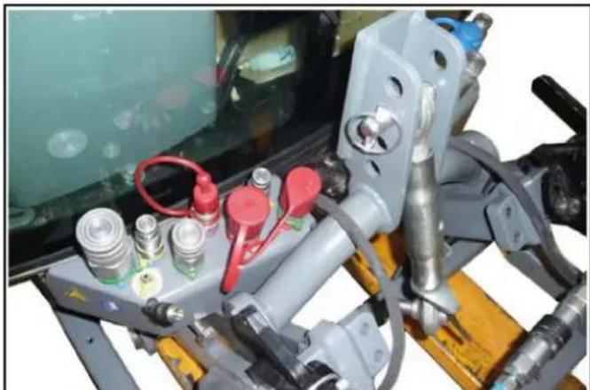
natural_image
Close-up of industrial machinery components with red and gray fittings (no visible text or symbols)
- Insert the front power lift into the mounting frame on the vehicle, all the way to the end stop.
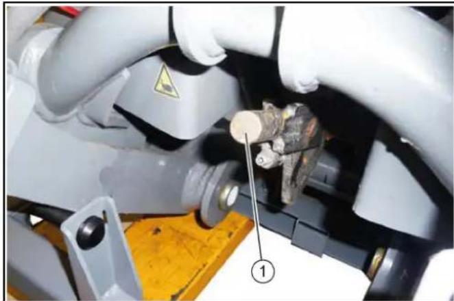
natural_image
Close-up of mechanical components with a numbered annotation pointing to a component (no readable text or symbols)
①Locking lever
- Move the locking lever downwards.
- Check the locking, see chapter Checking adjusting the attachment locking mechanism.
- Lower and retract the lift truck.
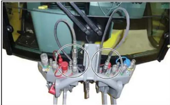
natural_image
Close-up of a mechanical device with multiple connectors and tubing, no visible text or symbols
- Depressurise the hydraulic system. See chapter Depressurise the hydraulic system (pressure relief).
- Connect the hydraulic hoses to the couplings.
Removing the front power lift
- Raise the front power lift.
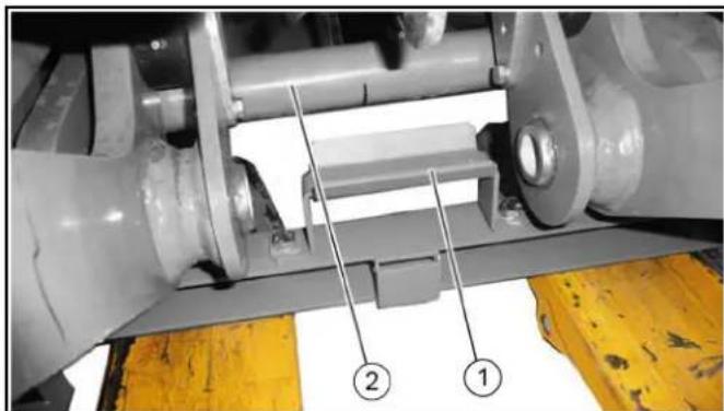
natural_image
Mechanical assembly diagram showing a shaft and housing with numbered components (no readable text or symbols)
①Changing carriage mounting
②Front power lift frame
- Use a lift truck to move the changing carriage under the front power lift.
a Raise the lift truck.
b Make sure that the frame of the front power lift is securely seated in the mounting of the removable frame.
-
Depressurise the front hydraulic system (pressure relief).
-
Release the hydraulic hoses.
a Fasten the hydraulic hoses to the front power lift with cable ties.
- Open the lock on both sides of the vehicle, see chapter "Opening/closing the lock".
- Use a lift truck to move the front power lift out of the vehicle mounting frame.
- Set down the front power lift in a safe place.
2-brush sweeping system attachment kit (pulled)
Installing the sweeping system
The pallet on which the sweeper system is delivered is also used as a mounting aid for attachment/removal.
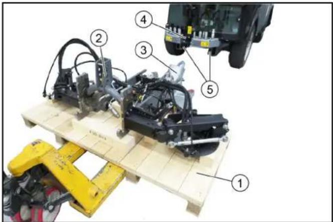
①Pallet
②2-brush sweeping system
③Suction mouth installed
④Locking lever in the upper position (open)
⑤Holder on the vehicle
- Move the lift truck under the pallet with the positioned sweeper system.
- Pull the locking lever upwards.
- Move the sweeper system into the holder on the vehicle and position it approximately 10 cm in front of the vehicle.
- Connect the hydraulic hoses, paying attention to the colour coding.
The connection assignments are described in a later chapter
- Connect the water hoses.
- Insert the device detection connector at the vehicle.
- Insert the sweeper system into the vehicle mounting bracket, all the way to the end stop.
- Lock the sweeper system by pressing the locking lever down (using the curved rod).
- The locking mechanism must be adjusted correctly via the adjusting nuts when the system is attached for the first time or transferred to another vehicle. When correctly adjusted, the locking mechanism must engage when pressed down beyond the dead point.
- Attach the side brushes.
View of the device for a 2-brush sweeping system
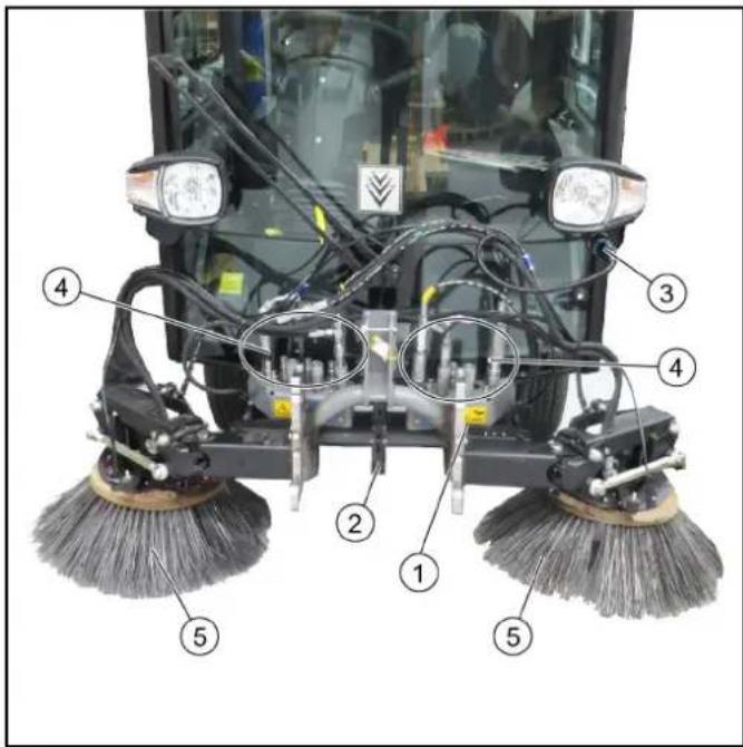
①2-brush sweeping system
②Locking lever
③Device detection plug
④ Hydraulic connection and water connection
⑤Side brushes
- Operation of the 2-brush sweeper system is described in a later chapter.
Connecting the high-pressure hoses and water hoses
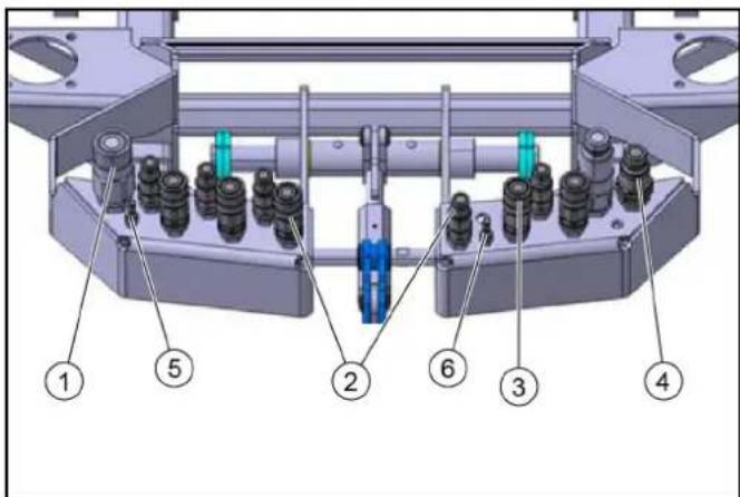
①Brush PTO
②Pivot suction mouth/sweeping brush
③Raise/lower sweeping brush
④Brush PTO
⑤Right-hand water connection
⑥Left-hand water connection
-
Plug in the hydraulic hoses according to the colour coding.
-
Plug in the water hoses at the left and right sides.
Operation
Control assignments for a vacuum sweeper with a 2-brush sweeper system (pulled)
Note
The indicators in the switches light when the switches are switched on.

① Left joystick
- Joystick forwards: Lower the brush arms simultaneously and switch on the side brushes
- Joystick backwards: Raise the brush arms simultaneously and switch off the side brushes
- Joystick to the left/right: Pivot the brush arms simultaneously
②Right joystick
Button is not used
③Raise/lower suction mouth
④ Hydraulic system on/off
⑤Button is not used
⑥ Button is not used
⑦Water circulation function on/off (recycling water)
⑧Suction fan on/off
⑨ ECO function
Switches the complete work program on.
PTO (side brushes, suction fan), fresh water, water circulation (recycling water)
⑩ Water pump on/off
(A) Sweeping brush speed selection, common for the left-hand and right-hand sides
(B) Button is not used
(C) Engine speed
Press to adjust the values
Note
The suction power depends on the set engine speed.
• 1600 rpm light waste
• 2200 rpm normal soiling
• 2500 rpm strong, heavy soiling
(D) Not used
(E) Left-hand and right-hand side brush contact pressure button
(F) Save button
Press to save adjusted values or programs
(G) Rotary knob
Press to change the adjusted values
Switching over to the 2-brush sweeping system (pulled):
1 Switch on the ignition.
2 Press F10 on the vehicle display.
3 Use F5 to select a pulled sweeper system.
A green bar in the display indicates a reduction in the brush contact pressure.
A red bar indicates an increase in the brush contact pressure.
Care work
1 The existing lubrication points (grease nipples) are labelled. Lubricate daily with multi-purpose grease.
2 Check the sweeping brushes for tangled cords and straps and remove as necessary.
3 Keep the hydraulic connections clean and check for leaks once a week.
4 Check the sweeping brushes for wear and damage and replace if necessary.
Adjusting the sweeping area
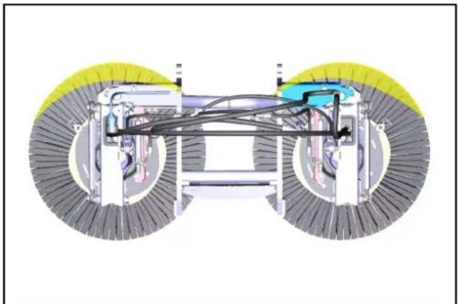
natural_image
Diagram of a vehicle chassis with two wheels and internal components (no text or symbols)
- Adjust the sweeping area as shown in the illustration.
Right: 9 am- 2 pm
Right-hand side: 10 am- 3 pm
Adjusting the side inclination
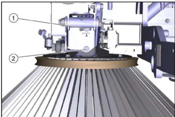
①Screw 1
②Screw 2
-
Unscrew the screws.
-
Adjust the side inclination via the rotation point of screw 1.
-
Tighten the screws.
Adjusting the head inclination forwards
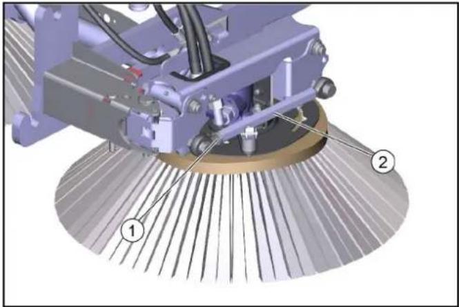
natural_image
Mechanical assembly diagram showing a robotic arm with labeled parts (1 and 2), no readable text or symbols present.
①Lock nut
②Hexagon head
5. Unscrew the counternut.
6. Adjusting the head inclination via the hexagon.
7. Tighten the counternut.
Adjusting the brush contact pressure
8. The brush system has a hydraulic brush contact pressure relief system.
Storage
△WARNING
Risk of injury and damage
Note the weight of the device.
ATTENTION
Risk of damage
Store the attachment kit in a protected, level and dry place. Ensure that the sweeping brushes are not loaded.
- Store the sweeping system that has been removed from the vehicle on the changing carriage.
- Ensure that the sweeping brushes are not loaded during attachment to the vehicle.
Technical data
| Dimensions and weights 2-brush s | sweeping sys-tem(pulled) |
| Length 950 mm | |
| Width 1250 mm | |
| Height 750 mm | |
| Weight (transport weight) 115 kg | |
Removing the sweeping system
Remove the sweeper system in the reverse sequence to the attachment procedure. Set the sweeping system down on the pallet. Remove the sweeping brushes first.
Always first depressurise the system before disconnecting the hydraulic hoses, see the corresponding section in the vehicle operating instructions.
3-brush sweeping system attachment kit (front brush)
Installing the sweeping system
The pallet on which the sweeper system is delivered is also used as a mounting aid for attachment/removal.
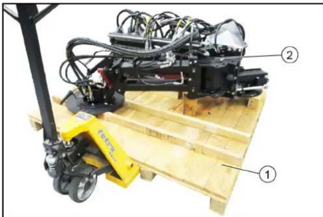
natural_image
Industrial robotic pallet with labeled parts (1, 2), no visible text or symbols on the device itself
①Pallet
② Sweeping system
- Move the lift truck under the pallet with the positioned sweeper system.

①Holder on the vehicle
②Suction mouth installed
③Sweeping system
④Pallet
- Pull the locking lever upwards.
- Position the sweeper system approximately 10 cm in front of the vehicle.
- Connect the hydraulic hoses, paying attention to the colour coding.
The connection assignments are described in a later chapter
- Connect the water hoses.
- Plugging in the electrical socket plug connection on the vehicle.
- Insert the sweeper system into the vehicle mounting bracket, all the way to the end stop.
- Lock the sweeper system by pressing the locking lever down (using the curved rod).
- The locking mechanism must be adjusted correctly via the adjusting nuts when the system is attached for the first time or transferred to another vehicle. When correctly adjusted, the locking mechanism must engage when pressed down beyond the dead point.
- Attach the side brushes and front brush.
View of the device for a 3-brush sweeping system
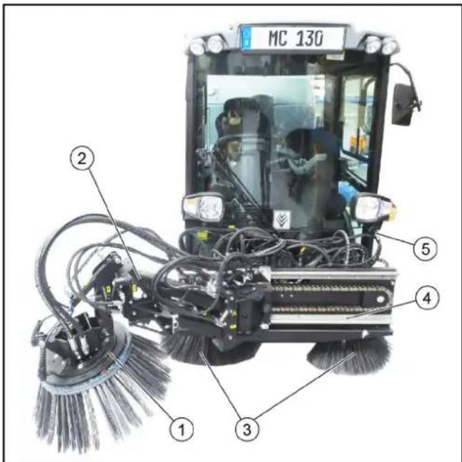
① Front brush
②Front brush arm
③2-brush sweeping system
④ Slide
⑤Device detection plug
- Operation of the sweeper system is described in a later chapter.
Connecting the high-pressure hoses and water hoses
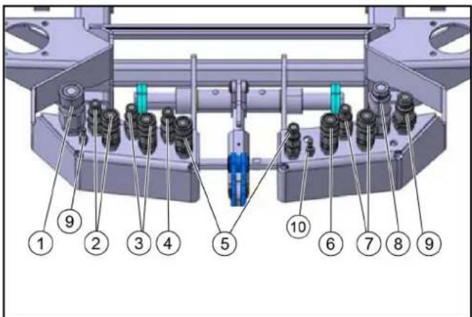
①Brush PTO
②Tilt/roll front brush
③ Raise/lower front brush
④Leakage oil
⑤Pivot suction mouth/sweeping brush
⑥Raise/lower sweeping brush
⑦ Pivot front brush
⑧PTO 80 l/min
⑨Brush PTO
⑩ Right-hand water connection
⑪ Left-hand water connection
-
Plug in the hydraulic hoses according to the colour coding.
-
Plug in the water hoses at the left and right sides.
Operation
Control assignments for a vacuum sweeper with a front brush sweeper system
Note
The indicators in the switches light when the switches are switched on.

① Left joystick for controlling the front brush
- Joystick forwards: Front brush lowers and switches on
Note
Increase the contact pressure in the case of heavy soiling
- Joystick backwards: Front brush raises and switches off
- Joystick to the left/right: Front brush moves to the left/right
②Right joystick for controlling the sweeping brush
- Joystick forwards: Lower the brush arms simultaneously and switch on the side brushes
- Joystick backwards: Raise the brush arms simultaneously and switch off the side brushes
- Joystick to the left/right: Pivot the brush arms simultaneously
③Raise/lower suction mouth
④Hydraulic system on/off
⑤Front brush rotation direction reversal
⑥ When activated: Tilt/roll the front brush with the right joystick
⑦Water circulation function on/off (recycling water)
⑧Suction fan on/off
⑨ ECO function
⑩Water pump on/off
(A) Front brush rotary speed selection
(B) Sweeping brush rotary speed selection
(C) Engine speed
Press to adjust the values
Note
The suction power depends on the set engine speed.
• 1600 rpm light waste
• 2200 rpm normal soiling
• 2500 rpm strong, heavy soiling
(D) Sweeping brush load relief
(E) Front brush load relief/pressure
(F) Save button
Press to save adjusted values or programs
(G) Rotary knob
Press to change the adjusted values
A green bar in the display indicates a reduction in the brush contact pressure.
A red bar indicates an increase in the brush contact pressure.
Using the weed brush
The front brush must be secured in the desired position when using the device as a weed brush.
Three positions are possible.
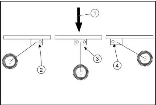
flowchart
graph TD
    A["Component 1"] --> B["Component 2"]
    B --> C["Component 3"]
    C --> D["Component 4"]
    D --> E["Component 5"]
①Travel direction
②Right position
③Front position
④ Left position
-
Secure the desired working position with bolts and spring pins. See chapter Transport lock.
-
Press the Change of rotation direction button when working in the Left position.
Transport lock
The front brush must be secured when driving on public roads (transport journeys).
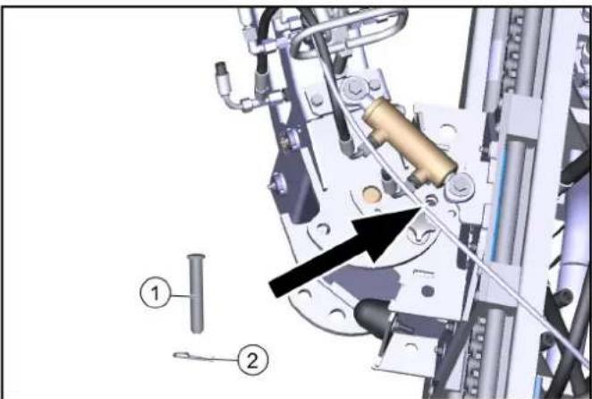
natural_image
Mechanical assembly diagram showing a mechanical component with numbered parts and an arrow indicating motion (no text or symbols present)
①Bolt
②Spring pin
-
Move the front brush carriage all the way to the left.
-
Secure the front brush in the corresponding position using a pin and spring pin.
Care work
Further information can be found in the operating instructions for the vehicle.
Maintenance and care of the sweeping unit
1 Check the front brush and sweeping brush for tangled cords and straps and remove as necessary.
2 Keep the hydraulic connections clean and check for leaks once a week.
3 Check the front brush and sweeping brush for wear and tear and replace if necessary.
Maintenance and care of the bearings/linear unit
△CAUTION
Malfunction or risk of damage
The bearing units are self-lubricating dry bearings and must never be lubricated with any lubricant.
Brake cleaners, lubricants or other cleaners can corrode and destroy the bearing foil. Check the bearing foil for wear and damage and replace if necessary.
1 The existing lubrication points (grease nipples) are labelled. Lubricate daily with multi-purpose grease.
2 Clean the entire linear unit with water or brine. Cleaning with a high pressure cleaner is not a problem.
Maintenance and care of the chain
ATTENTION
Notes on lubricating the chain
When lubricating the chain, make sure that no lubricant gets onto the rails of the linear unit. Should this happen due to carelessness, they must be cleaned and free of grease before initial start-up.
Never use stains or acids to clean the chain.
1 Inspect the chain at least once a month. During the inspection, clean the chain, tension the chain drive and lubricate it.
2 The chains can be cleaned with rags or brushes. Stubborn dirt can be loosened with petroleum or benzine. Apply new, suitable corrosion protection immediately after using grease-dissolving media.
3 The chain drive may only be tensioned by Kärcher Service.
4 Regular lubrication extends the service life. Lubricate the chain with relubricant VP8 FoodPlus Spay from IWIS. Note that the lubricant must get into the chain joint. This means that it has to get between the protective roller and the bushing, and also between the inner and outer plates to the pins and bushing
5 If you notice a lack of lubrication in the form of increased noise, stiff joints or fretting corrosion in the joints, we recommend the following procedure.
Clean the chain with a very low viscosity oil. This flushes fretting corrosion, old lubricant and other dirt from the joint. When the chain has been cleaned, lubricate it with a suitable lubricant as described above.
Adjusting the sweeping area
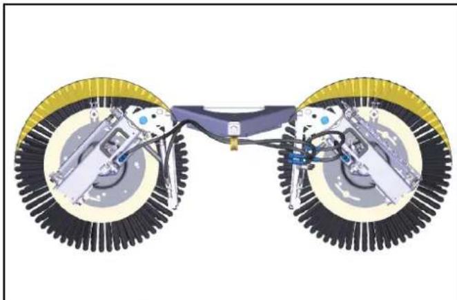
natural_image
Diagram of a bicycle's front wheel assembly showing two wheels with brake calipers and suspension components (no text or labels)
- Adjust the sweeping area as shown in the illustration.
Right: 9 am-2 pm
Right-hand side: 10 am- 3 pm
Adjusting the side inclination
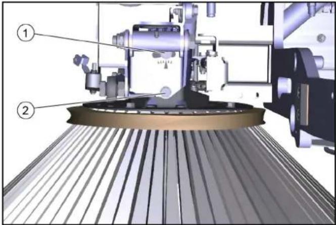
① Screw 1
②Screw 2
2. Unscrew the screws.
3. Adjust the side inclination via the rotation point of screw 1.
4. Tighten the screws.
Adjusting the head inclination forwards
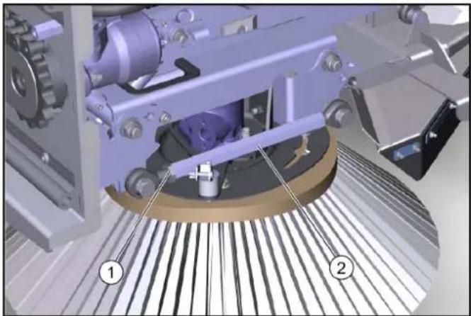
natural_image
Mechanical assembly diagram showing a rotating conveyor belt system with labeled components (no text or symbols present)
①Lock nut
②Hexagon
- Unscrew the counternut.
- Adjusting the head inclination via the hexagon.
- Tighten the counternut.
- The brush system has a hydraulic brush contact pressure adjustment system.
Storage
⚠ WARNING
Risk of injury and damage
Note the weight of the device.
ATTENTION
Risk of damage
Store the attachment kit in a protected, level and dry place. Ensure that the sweeping brushes are not loaded.
- Store the sweeping system that has been removed from the vehicle on the changing carriage.
- Ensure that the sweeping brushes are not loaded during attachment to the vehicle.
Technical data
| Dimensions and weights 3-brush sweeper system |
| Length 1800 mm | |
| Width 1250 mm | |
| Height 850 mm | |
| Weight (transport weight) 285 kg |
Removing the sweeping system
Remove the sweeper system in the reverse sequence to the attachment procedure. Set the sweeping system down on the pallet. Remove the sweeping brushes first.
Always first depressurise the system before disconnecting the hydraulic hoses, see the corresponding section in the vehicle operating instructions.
Transport
Loading the vehicle
△DANGER
Risk of injury due to incorrect transport
Mind the weight of the vehicle.
Slowly and carefully drive the vehicle onto the transport vehicle.
ATTENTION
Damage to vehicle
Do not load the vehicle with the crane.
Do not use a forklift.
- Slowly drive the vehicle onto the transport vehicle.
Note
If the vehicle is not ready for running, see Chapter Towing the vehicle.
Fastening the transport lock to the articulated joint

natural_image
Mechanical assembly diagram showing a shaft and frame components with numbered parts (1, 2, 3), no readable text or symbols present.
①Bolt with safety cotter
②Transport lock
③Transport lock storage
1. Pull out the safety cotters.
2. Pull out both bolts.
3. Remove the transport lock out from storage.
4. Attach the transport lock.
5. Insert the bolts.
6. Lock the bolts with safety cotters.
Securing the vehicle
△WARNING
Danger of accident
Secure the vehicle against slipping during transport.
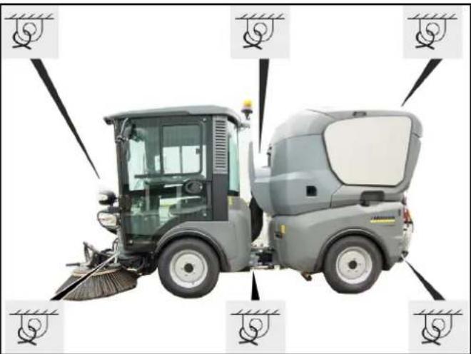
natural_image
Side view of a cleaning or cleaning service vehicle with visible brush and wheel controls (no text or symbols)
- Park the vehicle.
- Secure the vehicle with lashing straps on both sides at the illustrated lashing points.
Note
If the vehicle with waste container is loaded in reverse for transport, the cover of the waste container must be additionally secured with a strap to prevent it from opening.
Towing the vehicle
Fitting the towing eye
Note
The towing eye with retaining pin and locking pin are located in a storage compartment under the passenger seat.
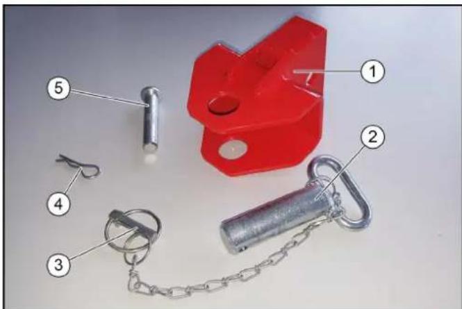
①Towing eye
②Retaining pins
③Locking pin
④Locking pin for bolt
⑤Bolt
- Open the storage compartment under the passenger seat and remove the towing eye.
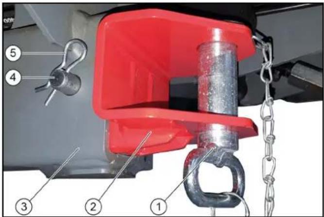
①Retaining pin with split pin
②Towing eye
③ Vehicle chassis
④Bolt
⑤Locking pin
-
Attach the towing eye at the front of the vehicle chassis on the right-hand side.
-
Insert the retaining pin into the towing eye and secure with the locking pin.
Fitting the towing eye
Note
The towing hook for MC 130 advanced is stored behind the passenger seat on a special holder along with the safety bolts and safety bracket.
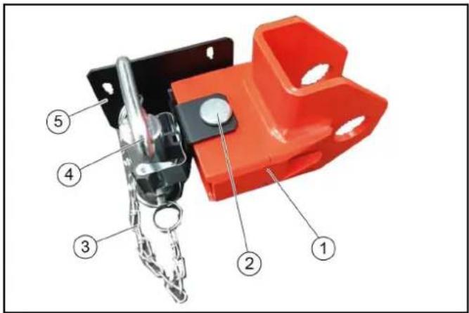
①Towing eye
②Safety bolt with safety bracket
③Safety chain with safety bracket
④Towing bolt
⑤Holder for towing eye
Attached behind the passenger seat
- Remove the towing eye with locking pin and safety bracket from the holder.
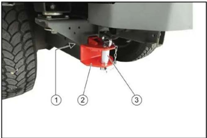
①Locking pin with safety bracket
②Towing eye
③Retaining pin with split pin
2. Attach the towing eye to the front of the vehicle frame.
3. Insert the retaining pin into the towing eye and secure with the locking pin.
Towing the vehicle
△CAUTION
Risk of damage due to incorrect towing
Only tow the vehicle away at walking speed.
Start up the towing vehicle slowly without jolting.
Fasten the towing rope or towing bar to the towing catch only.
Make sure the steering is working.
- Release the parking brake spring actuator.
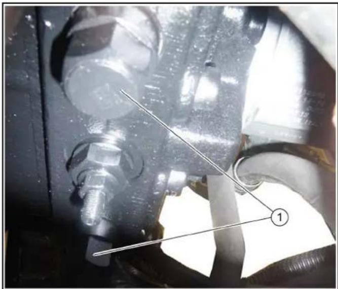
natural_image
Close-up of mechanical components with no visible text or symbols
①Bypass valves
- Unscrew the bypass valves 3 revolutions (width across flats 24 mm).
- Attach a towing bar or towing rope to the towing eye.
- Pull the vehicle slowly onto the transporting vehicle.
- Close the parking brake spring actuator and bypass valves.
Care and maintenance
General notes
△DANGER
Crush hazard
When working under raised attachments, ensure these are always mechanically locked (shimming).
- Before you clean and service the vehicle, or exchange parts or adjust them to a different function, switch off the motor and remove the ignition key.
-
Check if your radio is secured with a radio code before disconnecting the battery.
-
Disconnect the battery before working on the electrical system.
- Repairs may only be carried out by authorised customer service centres or by qualified staff in this area who are familiar with all relevant safety instructions.
- Any welding work on the vehicle or attachments is only permitted by authorised Kärcher Customer Service.
Service indicator
The service indicator lights up when the respective maintenance needs to be done.
The service indicator flashes on the display:
- after 50 operating hours when the initial inspection needs to be performed.
• Next service after 250 operating hours.
- Then every 500 operating hours.
Note
The service indicator must be reset by the Customer Service.
Maintenance intervals
Note
In order to preserve warranty claims, all servicing and maintenance work during the warranty period has to be performed by an authorised Kärcher Customer Service, in accordance with the inspection check list.
- Daily before starting operation, see chapter Safety checks before startup.
- Lubricate all bearings after washing the vehicle.
- If necessary have the safety checks according to the applicable local regulations performed by the Customer Service department.
- The intervals for inspection and maintenance work to be performed by the customer are listed in the following table. Additional maintenance work is to be carried out by the Customer Service department in accordance with the inspection checklist after 250, 500 (annually), 1000, 1500 or 2000 operating hours. Please inform the Customer Service department in time.
Vehicle maintenance plan
| Daily Weekly |
| Lubricate all bearings specified in the lubrication plan. | (8h) | |
| Check all Bowden cables and moving parts for freedom of movement. | X | |
| Check the side brushes and suction mouth for wear and tangled pieces of tape (for sweepers). | X | |
| If the device has been operated with the water circulation system switched off (option), clean the filter and valve of the water circulation system to ensure reliable operation of the water circulation system and prevent damage. | X | |
| Check the rollers at the suction mouth for freedom of movement (for sweepers). | | X |
| Check the spray pattern of the brush irrigation spray nozzles and in the suction mouth. Clean or replace the nozzles if necessary (for sweepers). | | X |
| Check all hoses and cable clamps. X | | |
| Check the coolant hoses. X | | |
| Clean the cooler fins on the water cooler, oil cooler and air-conditioning system. | X | |
| Check the V-belts and V-belt tension. X | | |
| Daily Weekly |
| Check that the parking brake functions correctly and is correctly adjusted. | X | |
| Checking the pedals for correct functionality | X | |
| Check the engine air filter. X | | |
| Clean cooler grille. X | | |
| Check the air-conditioning system. X | | |
| Check the exhaust system. X | | |
| Clean the blower chamber. X* | | |
| Clean the waste container and cover. X* | | |
| * several times daily in the case of heavy soiling | | |
Vehicle lubrication plan
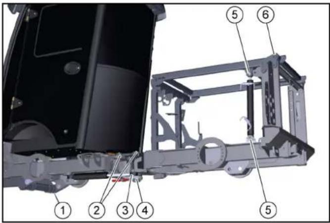
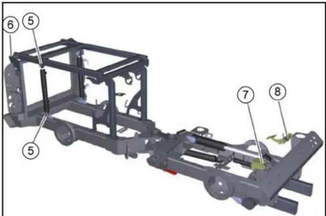
| Lubrication point Number | of lubrication points | Lubrication interval |
| 1 | Front power lifter slew bearing and lifting cylinder | 1 each | Every 8 h |
| 2 | Articulated steering at centre of vehicle | 2 | Every 8 hmaintenance-free (optional) |
| 3 | Steering cylinder | 2 | Every 8 hmaintenance-free (optional) |
| 4 | Lower articulated joint bearing | 1 | Every 8 hmaintenance-free (optional) |
| 5 | Lifting cylinder | 4 | Every 25 h |
| 6 | Lifting platform | 2 | Every 8 h |
| 7 | Accelerator pedal | 1 | Every 100 h |
| 8 | Brake pedal deflection lever | 1 | Every 100 h |
ATTENTION
Malfunctions
Keep the V-belt clean and free of grease.
1 Use high-grade multi-purpose grease.
2 Lubricate the grease nipples in accordance with the lubricating intervals (Table) using a grease gun.
Sweeping system lubrication plan
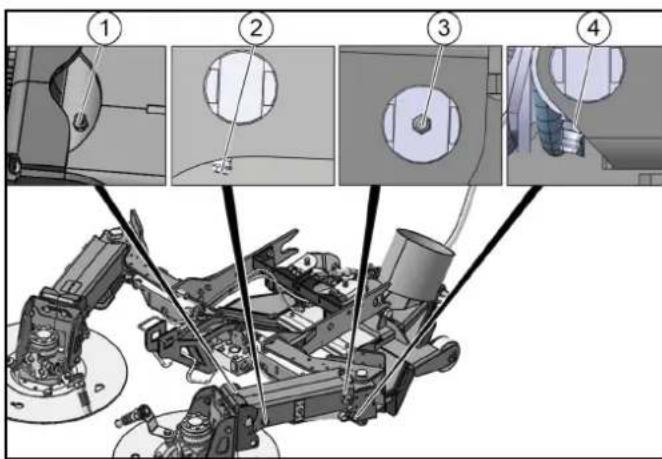
| Lubrication point Number | of lubrication points | Lubrication interval |
| 1 | Brush head lifting arm axle 1 each Every 8 h | 8 h | |
| 2 | Cylinder lifting arm axle 1 each Every 8 h | h | |
| 3 | Swivel bearing lifting arm axle 1 each Every 8 h | h | |
| 4 | Swivel bearing cylinder axle 1 each Every 8 h | h | |
ATTENTION
Malfunctions
Keep the V-belt clean and free of grease.
1 Use high-grade multi-purpose grease.
2 Lubricate the grease nipples in accordance with the lubricating intervals (Table) using a grease gun.
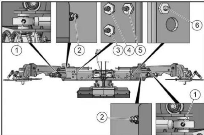
| Lubrication point Number | of lubrication points | Lubrication interval |
| 1 | Swivelling cylinder lifting arm axle 1 each Every 8 h |
| 2 | Swivel bearing base support axle 1 each Every 8 h |
| 3 | Suction mouth cylinder support 1 | Every 8 h |
| 4 | Suction mouth cylinder basic body 1 | Every 8 h |
| 5 | Swivelling cylinder base support axle 1 | Every 8 h |
| 6 | Swivelling cylinder base support axle 1 | Every 8 h |
Preparing for maintenance work
- Park the vehicle on a level surface.
- Switch off the suction fan.
- Lower the side brushes.
- Apply the parking brake.
- Secure the vehicle against rolling away.
- Switch off the ignition and remove the ignition key.
Maintenance work
General safety instructions
△DANGER
Risk of fatal injury from flowing road traffic
Bring the vehicle out of the hazard zone of flowing road traffic before starting any repair work.
Switch on the warning flashers.
Erect a warning triangle.
Don warning clothing.
△WARNING
Risk of injury and damage
Engine continues to run after switch-off.
Wait 5 seconds after switching off the engine.
Be sure to keep away from the working area during this period.
△CAUTION
Risk of damage through incorrect cleaning
The articulated joint, tyres, radiator fins, hydraulic hoses and valves, seals, electrical and electronic components must not be cleaned using a high-pressure cleaner.
Observe the respective safety regulations when cleaning the vehicle with a high-pressure cleaner.
Do not use aggressive cleaning agents.
Wash the vehicle only when the engine is switched off to protect the air filter.
△WARNING
Risk of injury and damage
The vehicle may start up unexpectedly.
Always remove the ignition key and disconnect the battery before performing any maintenance or cleaning work.
△WARNING
Risk of injury and damage
Maintenance work on the hydraulic system may only be performed by specially trained personnel.
△CAUTION
Risk of injury and damage
Always secure the tipping mechanism.
△DANGER
Danger of injury
Fully tip the waste container and lower the brush system/attachment unit to relieve the hydraulic system of pressure during all maintenance work.
The waste container can pivot to the rear. Always completely lower the waste container to the end position before performing work underneath the waste container.
The waste container can lower unintentionally. Perform work on the turbine only when the waste container is fully raised.
△CAUTION
Danger of burns
Allow the vehicle to cool down sufficiently.
Do not touch any hot components of the hydraulic system, hydrostatic drive motor, internal combustion engine or the exhaust system.
ATTENTION
Environmental pollution
Do not allow fluids such as engine oil, hydraulic oil, brake fluid, diesel or coolants to flow into the ground. Please protect the environment and dispose of liquids in an environmentally-friendly manner.
Securing the raised waste container
△WARNING
Risk of injury and damage
Always secure the waste container when working with a raised waste container.
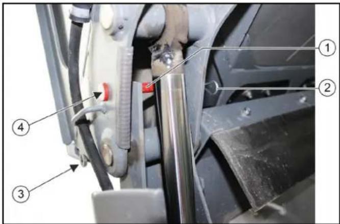
①Retaining pins
②Locking pin
③Storage for safety bolts with safety bracket (2x)
④Secured position (1x right, 1x left)
- When the waste container is raised, use safety bolts and secure with the safety brackets (2x).
Securing the tipping device

①Piston rod
②Locking pin
③Safety bracket
④Safety bracket mount
- Raise the tipping device all the way.
- Open the locking pin.
- Remove the support from the bracket.
- Insert the bracket.
- Fit the locking pin.
Note
Locking pins can be applied to the left and right piston rods.
Lowering the tipping device
ATTENTION
Damage to the suction hose
When lowering the tilting frame, make sure that the suction hose goes into its guide properly.
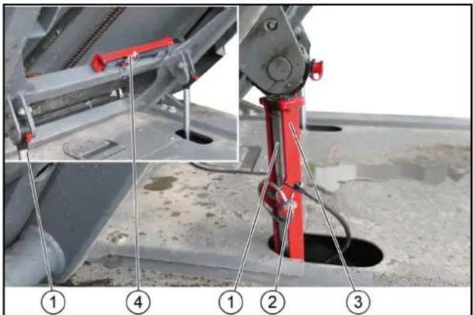
①Suction hose
- Lower the tilting frame after removing the safety support.
- If necessary, manually insert the suction hose into the guide.
Open the side panel
△CAUTION
Risk of injury
Risk of burns from hot vehicle parts.
Allow the unit to cool down sufficiently before opening the side panels.
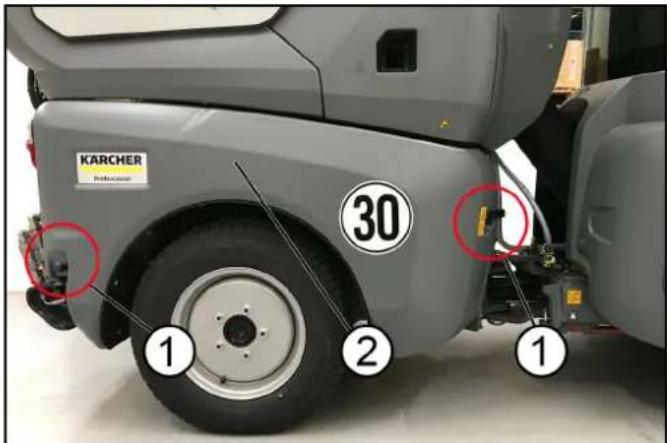
(1)Locks
(2)Side panel
On both sides
- Open side panel locks.
Right side
- Open the side panel towards the front.
Left side
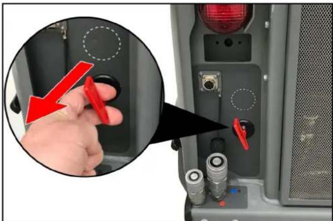
natural_image
Close-up of a computer interface showing a hand inserting a red tool into the button, with no visible text or symbols.
- Pull the main switch to unlock the left side panel.
- Open the side panel towards the front.
Removing/installing the radiator protective grille
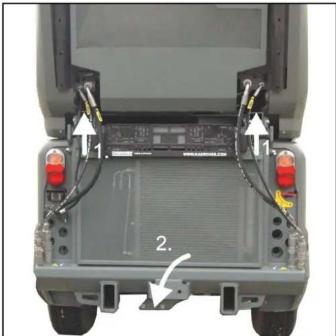
natural_image
Top-down view of a vehicle chassis back panel with visible wiring and labeled components (no text or symbols beyond labels)
- Lift the radiator protective grille upwards.
- Pull out the lower part.
- Remove the radiator protective grille downwards.
Engage the radiator protective grille at the bottom, then snap shut at the top.
Checking the coolant level and topping up the coolant
△CAUTION
Risk of burns on account of hot components
Do not open or touch the radiator or parts of the cooling system while the motor is hot.
ATTENTION
Damage to property due to incorrect coolant
Only top up coolant when the motor is cool.
Use water-based anti-freeze.
Do not mix different anti-freeze types.
Only used softened water.
For coolant refer to chapter.
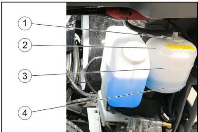
①Cover
② Expansion reservoir
③Upper filling level marking
④Lower filling level marking
- Check the filling level when the engine is cold.
-
Remove the left side panel.
-
Check the filling level in the expansion reservoir.
Note
The coolant level must be between the upper and lower markings.
- Top up the coolant if necessary.
- Also check the filling level in the radiator, see chapter.
- If the expansion reservoir is totally empty, top up the radiator first.
Checking the hydraulic oil level and topping up the hydraulic oil
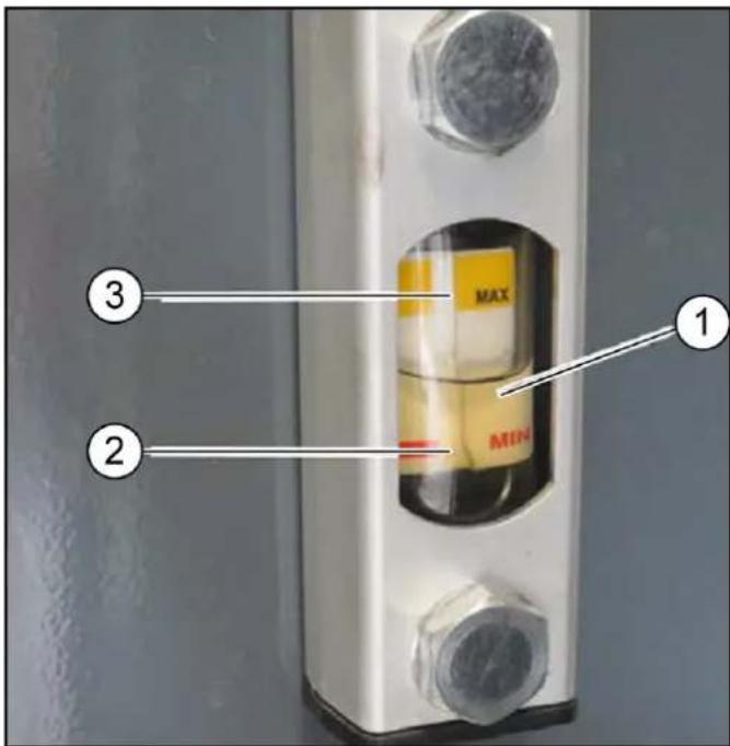
①Hydraulic fluid
②MIN oil level
③MAX oil level
- Check the hydraulic oil level.
Note
The hydraulic fluid must be between the upper and lower markings.
- Top up the hydraulic oil if necessary.
Note
Lacking hydraulic oil can be topped up using a special accessory tool connected to the leakage coupling on the vehicle. If required, request the order no. at Kärcher or have Kärcher Customer Service do the topping up.
For the hydraulic oil grade, see chapter Technical data.
Topping up the coolant in the radiator
△CAUTION
Risk of burns on account of hot components
Do not open or touch the radiator or parts of the cooling system while the motor is hot.
ATTENTION
Damage to property due to incorrect coolant
Only top up coolant when the motor is cool.
Use water-based anti-freeze.
Do not mix different anti-freeze types.
Only used softened water.
For coolant refer to chapter Technical data.
- Remove the waste container, see chapter
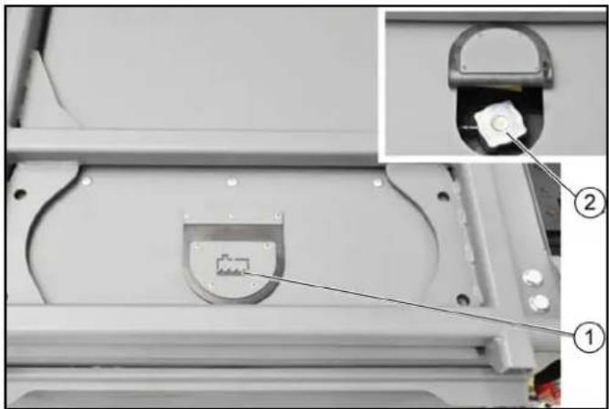
natural_image
Close-up of a mechanical component with a highlighted internal structure and an inset showing a pin inserted into a housing (no text or symbols visible)
①Radiator cap cover
②Radiator cap
2. Tilt up the radiator cap cover.
3. Turn the radiator cap one click and allow the pressure in the radiator to release.
4. Unscrew the radiator cap when the radiator has depressurised.
5. Slowly fill the radiator all the way to the top without air bubbles.
6. Screw the radiator cap on tight.
7. Refill the coolant expansion reservoir. See chapter .
8. Reattach the panel.
Installing/removing the battery
△DANGER
Danger of injury
Observe the safety regulations on the handling of batteries.
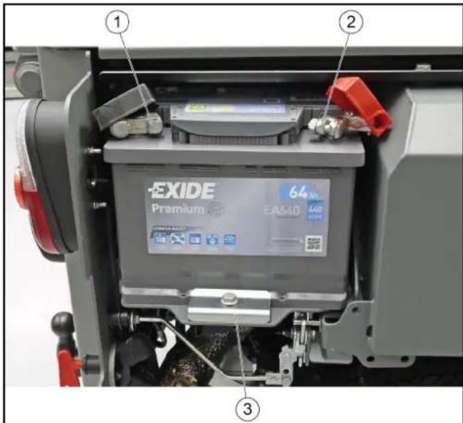
① Minus terminal
②Plus terminal
③Support
- Fit the battery into the battery holder.
- Screw the bracket on the battery base tight.
- Connect the terminal clamp (red cable) to the plus terminal (+).
- Connect the terminal clamp (black cable) to the minus terminal (-).
- Plug the cover caps onto the terminal clamps.
CAUTION
Always disconnect the minus terminal first when removing the battery.
Check that the battery terminals and terminal clamps are protected with a sufficient quantity of terminal grease.
Charging the battery
△DANGER
Risk of injury!
Only charge the battery with the appropriate charger.
Observe the safety instructions on the handling of batteries.
Follow the operating instructions of the charger manufacturer.
- Disconnect the minus terminal at the battery.
- Connect the charger to the battery.
- Insert the mains plug and switch on the charger.
- Charge the battery with as small a charging current as possible.
- After charging, first disconnect the charger from the mains and then from the battery (minus pole first).
- Reconnect the battery.
Cleaning/replacing air filters
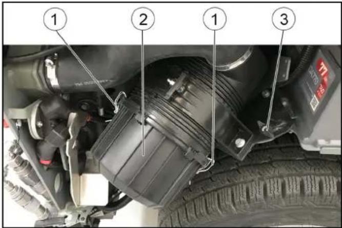
①Lock
②Air filter housing
③ Wing screw
- Remove the right-hand side motor cladding.
- Unscrew the wing screw approx. 2 turns
- Pivot the complete air filter unit outwards as far as it will go.
- Screw the wing screw tight.
- Open the locks (2x) on the air filter housing.
- Remove the air filter housing.
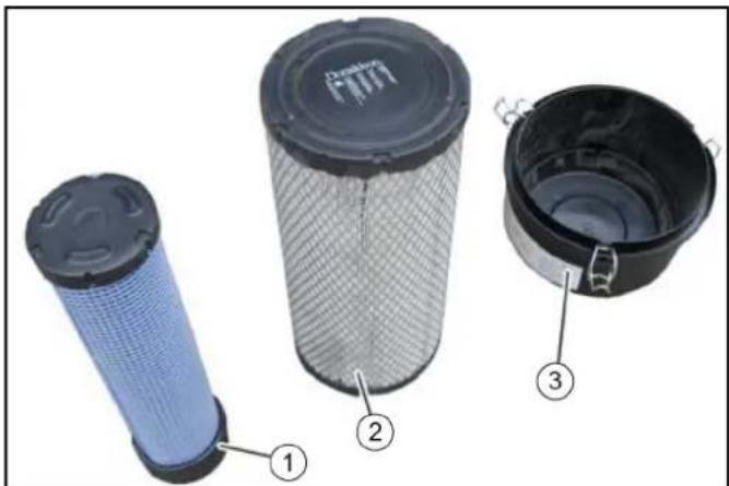
①Air filter housing
②Filter cartridge
③Safety cartridge
- Pull out the filter cartridge and safety cartridge.
- Clean the entire interior of the air filter housing.
- Knock the dust out of the filter cartridge on a hard surface. Do not blow out the filter cartridge with compressed air.
- Replace the safety cartridge with a new one.
Do not re-use a used safety cartridge.
- Check that the filter cartridge and sealing surfaces are clean and undamaged.
Replace a heavily soiled or damaged filter cartridge with a new one.
- After assembly, pivot the complete air filter unit inwards and tighten it using the wing screw.
Changing the dust filter on the outer cabin
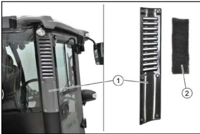
①Cover
②Dust filter
Note
Fine filter filter grade F8 (available as option)
- Unscrew the 6 screws for the cover.
- Remove the cover.
- Take out the dust filter.
- Blow out the slightly contaminated dust filter using compressed air (reduced pressure). Renew severely contaminated dust filter.
- Insert the new or cleaned filter.
Replace the dust filter in the cab interior
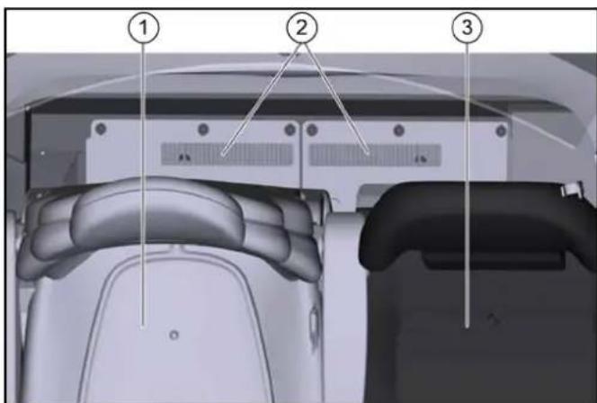
①Driver's seat
② Dust filter
③Passenger seat
- Push both seats forwards.
- Remove the dust filter.
- Check/clean the dust filter, replace if necessary.
Ensure the correct mounting position on re-installation.
Changing a wheel
△DANGER
Risk of fatal injury from flowing road traffic
Bring the vehicle out of the hazard zone of flowing road traffic before starting any repair work.
Switch on the warning flashers.
Erect a warning triangle.
Don warning clothing.
Note
Use a suitable, commonly available jack.
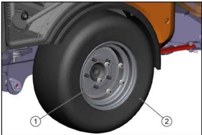
natural_image
Technical diagram of a vehicle's wheel assembly with labeled parts (1 and 2), showing components like tire, brake, and suspension components.
① Wheel nuts
②Wheel
- Park the vehicle on level and solid ground.
- Engage the parking brake and additionally secure the vehicle against rolling away.
- Secure the articulated joint.
- Remove the ignition key.
- Use a suitable tool to release the wheel nuts by approx. 1 turn.
- Fit the jack to the appropriate mounting point at the front or rear wheel and raise the vehicle with the jack.
- Additionally support the vehicle with axle stands or blocks.
- Unscrew the wheel nuts.
- Remove the wheel.
- Fit the new wheel and tighten all wheel nuts in a diagonal sequence all the way to their end stops.
11.Tighten the wheel nuts to a torque of 180 Nm.
Filling the water reservoir
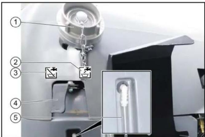
①Filling nozzle
②Symbol for the "Fill" lever position
③Symbol for the "Closed" lever position
④Switch lever
⑤Filling level display
- Open the cap on the filling nozzle.
- Switch lever in the "Fill" position.
- Fit a water supply hose onto the filling nozzle.
- Fill the water reservoir.
Note
To prevent back suction, the water hose must not be inserted into the water reservoir when filling.
- Close off the water inlet.
- Remove the water supply hose.
- Close the cap on the filling nozzle.
- Switch the switchover lever to the "Closed" position.
Filling the wiping water container
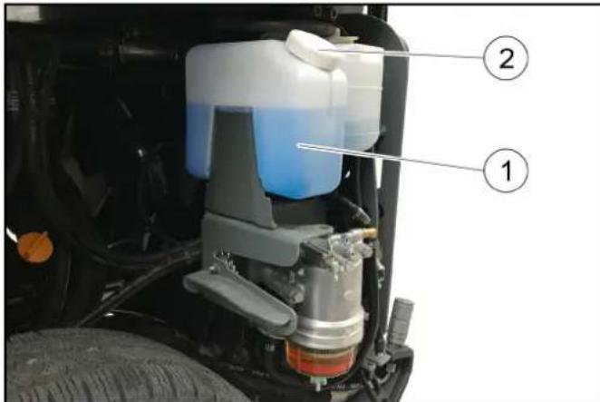
① Wiping water container
②Cover
③Hydraulic fluid reservoir filling level display
Note
Adhere to the manufacturer information for the wiping water and antifreeze.
- Raise the attachment frame.
- Unlock and remove the side panels.
- Fill with wiping water.
a Also add antifreeze in the case of potential frost.
- Fit the lid on the wiping water container.
- Attach the side panels again.
Checking the engine oil level
△CAUTION
Danger of burns
Do not touch any hot surfaces such as engines, motors or gearboxes.
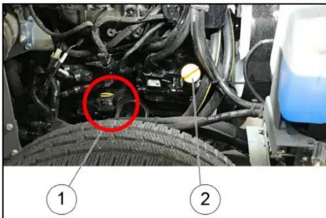
①Oil dipstick
②Cover
- Park the vehicle on a level surface.
- Remove the cover.
- Pull out the oil dipstick.
- Wipe the oil dipstick and insert it.
- Pull out the oil dipstick.
- Measure the oil level using the oil dipstick.
The oil level must lie between the "MIN" and "MAX" markings. Top up with engine oil if the oil level is below the "MIN" marking.
Topping up the engine oil
△CAUTION
Danger of burns
Do not touch any hot surfaces such as engines, motors or gearboxes.
△CAUTION
Risk of damage
An excessive high oil level leads to engine damage.
If the oil is above the "MAX" marking, drain oil until reaching the correct oil level.
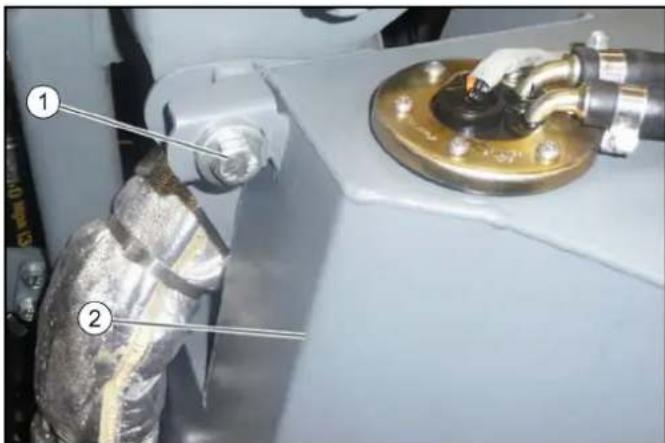
(1)Fuel tank fastener
(2)Fuel tank
- Remove the left-hand side motor cladding.
- Unscrew the fuel tank fastener screw and pivot the fuel tank outwards.
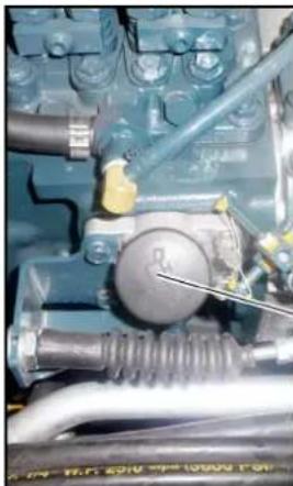
natural_image
Close-up of an internal mechanical component with hoses and a central knob (no visible text or symbols)
②

(1)Filler cap
(2)MC 130 advanced plus filler cap
- Check the engine oil level, see chapter .
- Open the filler cap.
- Top up the engine oil.
For the engine oil specifications, see chapter Technical data.
- Do not fill the engine above the "MAX" marking.
- Close the filler cap.
- Check the engine oil level again after 5 minutes.
Top up the engine oil if necessary.
Replacing the engine oil filter
△WARNING
Danger of burns
Allow the vehicle to cool down sufficiently before changing the engine oil and engine oil filter.
Note
The engine oil is easier to drain when the engine is warm.
- Switch off the engine.
- Place a catch pan (min. 10 litres) underneath.
- Unscrew the oil drain plug.
- Unscrew the filler cap.
- Drain oil.
- Unscrew the oil filter.
- Clean the mounting and sealing surfaces.
- Coat the seal of the new oil filter with oil.
- Screw in the oil filter and hand-tighten.
10.Screw in the oil drain plug (tightening torque 60 Nm).
11. Pour in the engine oil.
12.Close the filler cap.
13. Allow the engine to run for 30 seconds.
14.Wait 5 minutes.
15. Check the oil level.
Renew the seals.
Check for leaks.
Bleeding the fuel system
Air must be bled from the fuel system if the fuel tank has been run empty of the fuel filter has been changed.
- Fill the fuel tank.
- Set the ignition switch to position I.
The pump runs audibly quieter after 2-5 minutes.
Replacing the side brush
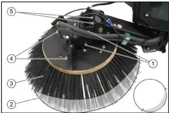
①Side screws
②Sweeping area
③Side brushes
④Nuts (4x)
⑤Rear screws
- Raise the side brushes.
- Release the nuts.
- Remove the side brush.
- Fit the new side brush and screw in place.
Adjusting the sweeping area
Adjust the sweeping pattern according to the illustration using the rear and side screws.
Flushing the water circulation system (option)
- Disconnect the water circulation system hose coupling.
- Connect the water supply hose to the water circulations system and flush the system.
- Set the irrigation switch to the water circulation system position
The end of the suction pipe is better irrigated.
Empty the water reservoir
- Open the valve on the drain hose (on the left under the waste container).
- Allow the water to drain.
Cleaning
△CAUTION
Risk of injury and damage
Always secure the tipping mechanism.
- Park the vehicle on a level surface.
- Switch off the ignition and remove the ignition key.
- Apply the parking brake.
- Switch off the main switch.
Cleaning the vehicle
Clean the vehicle daily after finishing work.
△CAUTION
Risk of damage through incorrect cleaning
The articulated joint, tyres, radiator fins, hydraulic hoses and valves, seals, electrical and electronic components must not be cleaned using a high-pressure cleaner.
Observe the respective safety regulations when cleaning the vehicle with a high-pressure cleaner.
Do not use aggressive cleaning agents.
Wash the vehicle only when the engine is switched off to protect the air filter.
- To avoid a risk of fire, check the vehicle for escaping oil and fuel. Have leaks repaired by Customer Service.
- Clean all plant residues and oil from the engine, muffler, battery and fuel tank to avoid a risk of fire.
- If necessary, clean the engine with a brush, compressed air or with low water pressure if necessary.
- Clean the wheel mudguards.
Cleaning the radiator
- Remove the radiator protective grille, see chapter Removing/installing the radiator protective grille.
- Manually remove coarse dirt deposits from the engine radiator, air-conditioner radiator and fuel cooler.
- Clean the engine radiator, air-conditioner radiator and fuel cooler with a soft brush, compressed air (max. 5 bar) or with low water pressure.
Clean the waste container and cover
Waste container is emptied.
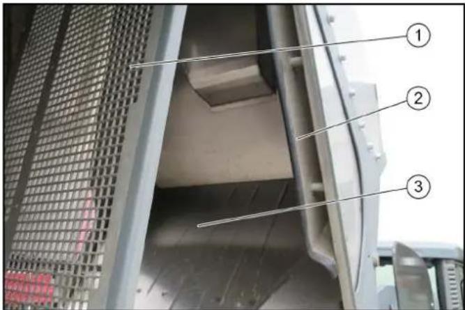
①Diffusor grille
② Waste water sieve
③ Waste container
- Raise the waste container.
- Remove the locking pins from the diffusor grille.
- Clean the waste container and the cover with a water jet.
- Clean the area behind the waste water sieve with a water jet.
Cleaning the blower
The waste container must be raised.
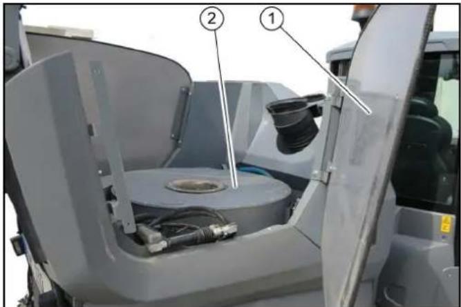
①Side cover
②Blower chamber
- Secure the waste container.
- Pivot out the side cover.
- Remove dirt from the fan grille and clean with a moist cloth.
Cleaning the vacuum system
Waste container emptied.
Motor running.
ATTENTION
Damage due to soiled vacuum system
A soiled vacuum system can lead to the blower fan running out-of-round and to vehicle vibrations.
Check the vacuum system for soiling and clean if necessary.
- Switch on the PTO.
- Set the motor speed to approx. 2200 rpm
- Switch on the blower fan.
- Using a water hose, spray fresh water into the suction mouth area.
The water is collected in the waste container. The cleaning process is completed when clean water exits at the diffuser.
- Empty waste container.
- Keep running the blower to dry the waste container.
Contact Customer Service if, in spite of thorough cleaning, vibrations are still present (caused by the suction blower running out-of-round).
Cleaning the water filter
- Raise the waste container.
- Open the left-hand advertising panel.
- Unlock the water filter and remove it from the holder.
- Unscrew the filter casing.
- Clean the water filter.
- Insert the filter.
- Check for correct seating.
- Screw the filter casing tight.
- Place the water filter in the holder and lock it.
- Close the left-hand advertising panel.
- Lower the waste container.
Clean the spray nozzles
Note
The spray nozzles are located on the side brushes and suction mouth.
- Remove the spray nozzles.
- Clean the spray nozzles with a brush/compressed air.
- Install the spray nozzles.
Cleaning the recycling water valve
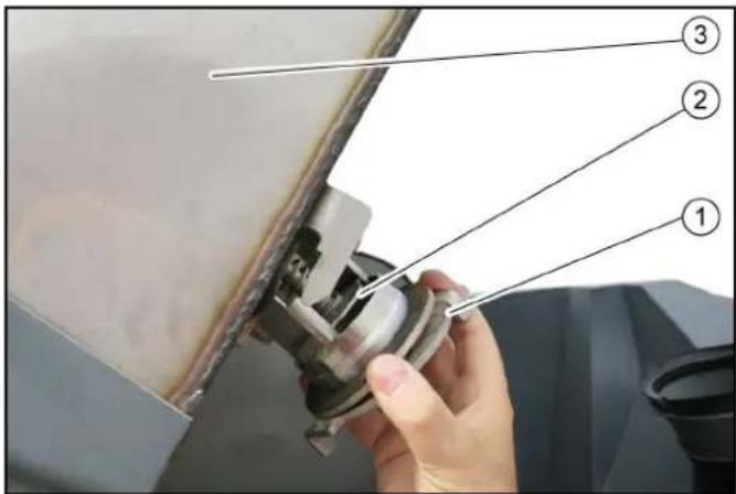
①Bayonet connection
②Recycling water valve
③ Waste container
- Empty the waste container.
- Raise the waste container.
- Open the bayonet connection.
- Remove the valve.
- Clean the valve under running water.
- Insert the valve.
- Close the bayonet connection.
Fuses
The fuses are located behind a cover behind the driver's seat.
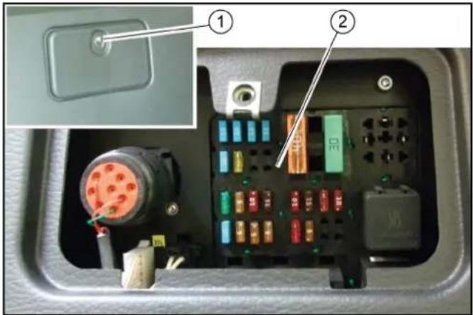
①Cover
②Fuses
- Open cover.
- Replace defective fuses.
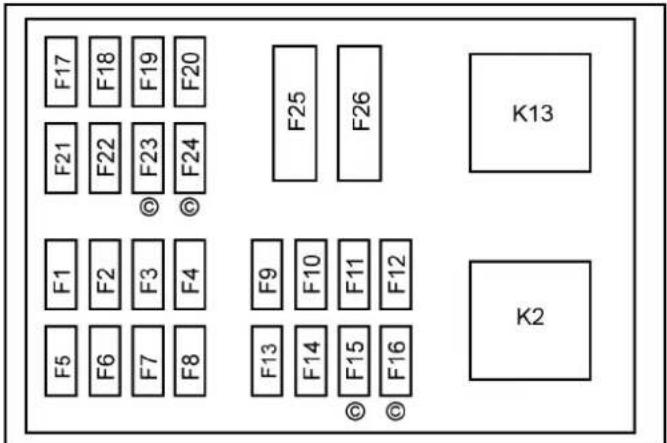
Note
Use only fuses with the same ampere rating.
| Fuse Function | A | |
| F1 Fuel valve | CR* control unit | 30 |
| F2 BODAS control unit, display 5 | |
| F3 Limiter lamp | Interior lighting | 10 |
| F4 Spray pump | 7.5 | |
| F5 Warning flasher system 15 | |
| F6 Rear fog lamp | 5 | |
| F7 Left limiter lamps | 5 | |
| F8 Right limiter lamps | 5 | |
| F9 Windscreen wiper Differential lock | 10 |
| F10 | Radio High-pressure cleaner | 7.5 |
| F11 | Travel direction indicator | 10 |
| F12 | Flashing beacon | 10 |
| F13 | Driving pump, indicator | 7.5 |
| F14 | Motor | 5 |
| F15 | CR* exhaust gas return valve | 5 |
| F16 | CR* air volume sensor | 5 |
| F17 | Headlights | 15 |
| F18 | Work lights | 15 |
| F19 | Cabin ventilation | 15 |
| F20 | Seat heater Mirror heater | 15 |
| Fuse Function | A | |
| F21 | Cabin accessoriesFront connector, attached equipment | 15 |
| F22 | Seat compressorRear connector, distributor | 30 |
| F23 | Start switch (ignition switch) 5 | |
| F24 | Windscreen heater | 30 |
| F25 | Preheating | 40 |
| F26 | BODAS control unit | 30 |
| F31 | Main fuse at the engine | 70 |
| * CR = Common Rail motor (MC 130 Advanced plus) |
Storage
△WARNING
Risk of injury and damage
Note the weight of the device.
- Park the vehicle in a safe, level and dry place, leave the main switch on.
- Change the motor oil and the oil filter.
- If frost is expected, check if there is enough antifreeze in the coolant.
- Empty the water container and the pipe system.
- With a recycling system (option), drain the water out of the waste container.
- Switch off at main switch.
- Clean the inside and outside of the vehicle.
- Jack up the vehicle if it is in storage for more than one month.
- Disconnect battery.
Troubleshooting guide
You can remedy minor faults using the following overview. If in any doubt, please contact your authorised Customer Service.
Repair work and work on electrical components must only be performed by your authorised Customer Service.
△DANGER
Risk of electric shock
Switch off the vehicle before carrying out any care and maintenance work, and remove the key.
Vehicle malfunctions
| Malfunction | Remedy |
| Vehicle does not start | Check / charge the battery.Switch on the main switch.Sit in the driver's seat (seat contact switch is activated).Set the driving direction lever to the NEUTRAL position - central position.Fill up fuel, bleed the fuel system.Check, clean and/or replace the fuel filter.Check the fuel connections and lines.Contact an authorised Customer Service department. |
| Motor running irregularly | Clean/replace the air filter.Check, clean and/or replace the fuel filter.Fill up fuel, bleed the fuel system.Check the fuel connections and lines.Contact an authorised Customer Service department. |
| Engine is running, but the device does not drive or just slowly | Release the parking brake.Check the position of the neutral lever.Have the oil level of the drive hydraulics checked by Customer Service.In the event of freezing temperatures and cold hydraulic oil: Allow the device to warm up for at least 3 minutes. |
| Motor does not switch off (main switch to 0) | Close the fuel cock at the fuel filter.Unplug the fuel supply pump.In the event of repeated occurrences, contact Customer Service. |
| Malfunction Remedy | |
| Dust when sweeping / insufficient suction power | ● Empty the waste container.● Switch on the suction fan.● Check the hose on the suction fan.● Check / replace the seals:a Suction fan sealing collar.b Filter chamber seal.c Waste container seals.● Check / clean / replace the dust filter.a Check that the dust filter is firmly in place.b In case of light soiling, clean the dust filter.c In case of damage or heavy soiling, replace the dust filter.● Check the sealing strips for wear / set / replace them. |
| Sweeping performance not satisfactory | ● Check the roller brush and side brush for wear, replace them as necessary.● Check the sealing strips for wear, replace them as necessary.● Check that the coarse dirt flap is fully functional.● Check that roller brush halves are correctly in place.● Check the filling level of the hydraulic oil tank.● Check the hydraulic system for leaks. |
| Activation of side brushes not working | ● Contact Customer Service. |
| The side brushes are not running | ● Check the filling level of the hydraulic oil tank.● Check the hydraulic system for leaks.● Check the side brushes for any tangled pieces of tape. |
| Waste container emptying does not work | ● Contact Customer Service. |
Note
In case of all malfunctions not listed, contact Customer Service!
Error messages for symbol displays
| Malfunction Cause Remedy | | |
 | Coolant temperature is too high. ● Switch off the motor.● Clean the radiator (see chapter "Cleaning the radiator").● Check the level of coolant in the motor, refill as necessary.● If the warning light does not go out within 5 minutes: a Switch off the engineb Contact Customer Service |
 | Hydraulic oil temperature too high. | ● Operate the engine in idling mixture until the warning light goes out. |
 | Hydraulic oil temperature too low. | ● Carefully warm up the engine until the warning light goes out. |
 | Engine oil pressure is too high. ● Call Customer Service. |
 | Parking brake active. ● Release the parking brake. |
 | Low fuel level. ● Top up the fuel. | ● Vent the fuel system if the tank was run dry. |
 | Battery is not charging. ● Call Customer Service. |
 | Regeneration process required. | ● Perform regeneration (see chapter "Regeneration"). |
 | Service required. | ● Have the device serviced by Customer Service.a The service display must be reset by Customer Service. |
Coded error messages
The following coded error messages can occur when operating the level V engines V2403-CR-TE4B-KRC-1 (MC 130 plus, MC 130 classic).
When an error is indicated while the engine is running, the indicator lamp flashes and an error code may also be shown on the display.
| PCD Error Indicator lamp blinks |
| P3014 1 Hz (1 second interval) |
| P1A28 1 Hz (1 second interval) |
| P3015 1 Hz (1 second interval) |
| P2455 1 Hz (1 second interval) |
| NCD error Indicator lamp blinks |
| U0076 1Hz (one second interval) + on for 5 seconds + 1 Hz (one second interval) + on for 5 seconds ... |
| P0102 1Hz + on for 5 seconds + 1 Hz + on for 5 seconds ... |
| Malfunction Cause Remedy | | |
| U0076 No communication with exhaust gas recirculation | ● Engine loses power and the exhaust emission performance becomes worsea Contact Customer Service |
| P0102 | Air mass sensor not normal | ● Engine loses power and the exhaust emission performance becomes worsea Contact Customer Service |
| P03014 / P1A28 | Fault in the DPF system | ● Engine loses power and the exhaust emission performance becomes worsea Contact Customer Service |
| P3015 | No DPF function | ● Engine loses power and the exhaust emission performance becomes worsea Contact Customer Service |
| P2455 | Differential pressure sensor not normal | ● No change in behavioura Contact Customer Service |
Emergency operation hydraulic valve
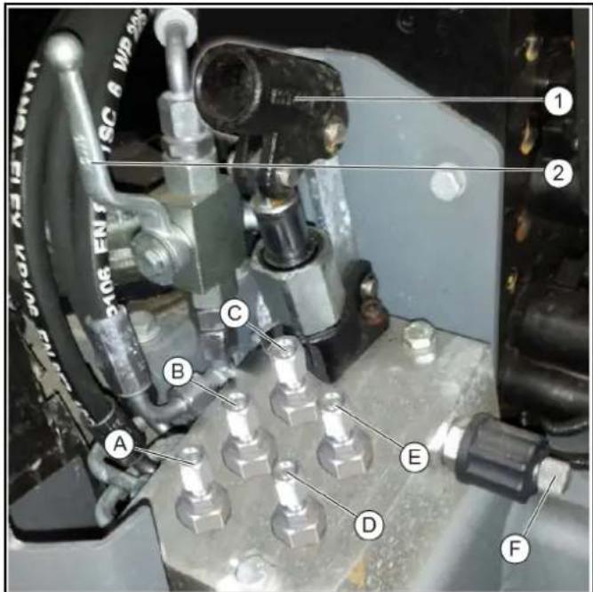
Raise the waste container/attachment frame
- Unscrew the screws (B, E, F).
- Actuate the manual pump (1).
Waste container/attachment frame raises.
- Slowly screw in screw (F).
Waste container/attachment frame lowers.
- Screw in the bolts.
Original position is restored.
Raising the front power lift/suction mouth
- Unscrew the screws (A, D, F).
- Actuate the manual pump (1).
Front power lift/suction mouth raises.
- Slowly screw in screw (F).
Front power lift/suction mouth lowers.
- Screw in the bolts.
Original position is restored.
Releasing the parking brake spring actuator
- Move the ball tap (2) to the horizontal position.
- Unscrew screw (C).
- Actuate the manual pump (1). Spring actuator releases.
- Move the ball tap to the vertical position.
- Screw in screw (C).
Spring actuator is actuated (original position).
①Manual pump
②Ball tap - normal operation
(A) - (E) 8mm screws
(F) Knurled screw
- Remove the cover, then unlock the cover screws (3x) by turning to the left.
Note
A pipe is required for operating the manual pump and this is located at the side behind the driver's seat.
An 8mm ring spanner to actuate the screws is included.
Accessories and spare parts
Only use original accessories and original spare parts. They ensure that the appliance will run fault-free and safely.
Information on accessories and spare parts can be found at www.kaercher.com.
Spare parts list
| Order no. Description Quantity Figure | | |
| 6.422-522.0 LED working light 2 | |  |
| 9.654-350.0 Wiper arm 1 | |  |
| 9.654-351.0 Wiper blade 1 | | 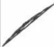 |
| 9.989-357.0 Signal horn 1 | |  |
| Order no. | Description | Quantity Figure | |
| 9.656-126.0 Air | filter on hydraulic oil tank | 1 |  |
| 2.852-393.0 Fire | dust air filter 1 | |  |
| 6.996-448.0 Light bulb 2 | | 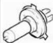 |
| 7.651-027.0 Lamp 2 | |  |
| 7.651-028.0 Lamp 2 | |  |
Subject to technical modifications.
Technical data
| | MC 130 Classic MC 130 | MC 130 Plus |
| Device performance data |
| Travel speed (max.) | km/h | 30 (25) | 30 (25) | 40 (30, 25) |
| Working speed (max.) | km/h | 20 | 20 | 20 |
| Climbing ability (max.) | % | 18 | 25 | 25 |
| Driven wheels | | 2 | 4 | 4 |
| Theoretical surface performance | m^2/h | 24000 | 24000 | 24000 |
| Working width | mm | 1200 - 2400 | 1200 - 2400 | 1200 - 2400 |
| Turning circle | mm | 1173 | 1173 | 1173 |
| Min. working width | mm | 1200 | 1200 | 1200 |
| Standard working width | mm | 1540 | 1540 | 1540 |
| Battery |
| Battery type | | Maintenance-free | Maintenance-free | Maintenance-free |
| Battery capacity | Ah | 80 | 80 | 80 |
| Working voltage of the battery | V | 12 | 12 | 12 |
| Dimensions and weights |
| Length | mm | 3955 | 3955 | 3955 |
| Width | mm | 1540 | 1540 | 1540 |
| Height | mm | 2000 | 2000 | 2000 |
| Net weight (transport weight) | kg | 2275 | 2275 | 2275 |
| Approved total weight | kg | 3500 | 3500 | 3500 |
| Maximum permissible front axle load | kg | 2000 | 2000 | 2000 |
| Maximum permissible rear axle load | kg | 2000 | 2000 | 2000 |
| Permissible braked trailer (option) load | kg | 3000 | 3000 | 3000 |
| Permissible unbraked trailer (option) load | kg | 750 | 750 | 750 |
| Trailer coupling (option) vertical load | kg | 250 | 250 | 250 |
| Waste container |
| Waste container volume (gross) | I (m^3) | 1300 (1.3) | 1300 (1.3) | 1300 (1.3) |
| Discharge height (max.) | mm | 1550 | 1550 | 1550 |
| Water reservoir capacity | I | 195 | 195 | 195 |
| Side brush |
| Diameter of side brush | mm | 900 | 900 | 900 |
| Side brush speed (continuously variable) | 1/min | 0 - 110 | 0 - 110 | 0 - 110 |
| Internal combustion engine |
| MC 130 Classic | MC 130 | MC 130 Plus |
| Engine type Yanmar | 3TNV86CT - DKEV | Yanmar3TNV86CT - DKEV | Kubota V2403-CR-T-EW03 |
| Type 3-cylinder four- | stroke diesel en-gine with diesel particle filter (DPF) | 3-cylinder four-stroke diesel en-gine with diesel particle filter (DPF) | 4-cylinder four-stroke diesel en-gine with diesel particle filter (DPF) |
| Engine capacity cm | ^3 | 1568 1568 2434 | | |
| Cooling type Water Water Water |
| Engine power at 2700 rpm kW 32.4 32.4 48.0 |
| Engine oil type Shell Rimula R6 | LM 10W-40 | Shell Rimula R6LM 10W-40 | Shell Rimula R6LM 10W-40 |
| Engine oil volume | I | max. 6.7 | max. 6.7 | max. 9.5 |
| Fuel tank capacity | I | 50 | 50 | 50 |
| Fuel type | I | Diesel | Diesel | Diesel |
| Coolant (SAE J814C) | | Havoline XLC Anti-freeze | Havoline XLC Anti-freeze | Havoline XLC Anti-freeze |
| Hydraulic oil as per DIN 51524, Part 3 | | Renol B HV 46 | Renol B HV 46 | Renol B HV 46 |
| Hydraulic oil quantity | I | 43 | 43 | 43 |
| Determined values in acc. with EN 60335-2-72 |
| Sound pressure level L_pA | dB(A) | 75 | 75 | 74 |
| Uncertainty K_pA | dB(A) | 3 | 3 | 3 |
| Sound power level L_wA | dB(A) | 109 | 109 | 104 |
| Uncertainty K_wA | dB(A) | 3 | 3 | 3 |
| Hand-arm vibration value | m/s^2 | 0.8 | 0.8 | 0.4 |
| Uncertainty K | m/s^2 | 0.2 | 0.2 | 0.2 |
| Seat vibration value | m/s^2 | 0.2 | 0.2 | 0.5 |
| Uncertainty K | m/s^2 | 0.1 | 0.1 | 0.2 |
| Grease |
| Multi-purpose grease | | For manually lubricated lubrication points | For manually lubricated lubrication points | For manually lubricated lubrication points |
Tyres
The tyre pressures for various different axle loads and different speeds are listed in the following table.
| Maxxis Vansmart A/S AL2 205/65C 8PR 107/105 TL All year tyres |
| Axle load (kg) | 1000 | 1200 | 1400 | 1600 | 1800 | 1950 |
| Tyre pressure (bar) | 3.0 | 4.75 |
| Toyo 195/75 R14C 106/104 RWinter tyres (M + S) |
| Axle load(kg) | 1000 | 1200 | 1400 | 1600 | 1800 | 2000 |
| Tyrepressure(bar) | | 5.0 |
| BKT LG306 26x12-12 8 PLYGrass tyres |
| Axle load(kg) | 1000 | 1200 | 1400 | 1600 | 1800 | 2000 |
| BKT LG306 26x12-12 8 PLYGrass tyres |
| Tyre pressure(bar) at 30 km/h | 1.0 | 1.0 | 1.3 | 1.6 | 2.0 | 2.4 |
| Tyre pressure(bar) at 40 km/h | 1.0 | 1.1 | 1.5 | 1.8 | 2.2 | 2.6 |
| Deestone D408 26x12-12.00 - 12 10 PLY Traction tyres |
| Axle load (kg) | 1000 | 1200 | 1400 | 1600 | 1800 | 2000 |
| Tyre pressure (bar) at 30 km/h | 1.3 | 1.5 | 1.8 | 2.0 | 2.5 | 2.9 |
| Tyre pressure (bar) at 40 km/h | 1.3 | 1.5 | 1.8 | 2.0 | 2.5 | 2.9 |
Adjusting protective covers to different tyres
The protective covers can be adjusted to suit different tyre widths.
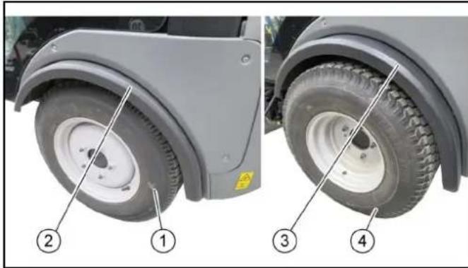
natural_image
Close-up of two views of a vehicle wheel rim and tire, labeled 1 to 4, showing tread patterns and mounting points (no text or symbols beyond labels)
①Tyres, narrow
② Protective cover pushed in
③ Protective cover pulled out
④Tyres, wide
- Release the screws, three each at the front.
- Adjust the protective cover to suit the width of the tyres.
- Unscrew the screws, three each at the rear.
- Offset the protective cover.
- Re-tighten all screws.
We hereby declare that the machine described below complies with the relevant basic safety and health requirements in the EU Directives, both in its basic design and construction as well as in the version placed in circulation by us. This declaration is invalidated by any changes made to the machine that are not approved by us.
Product: Sweeper
Type: PF-D
Currently applicable EU Directives
2006/42/EC (+2009/127/EC)
2014/30/EU
2000/14/EC
Harmonised standards used
EN 13019
EN ISO 14982:2009
2000/14/EC: Annex V
Sound power level dB(A)
PF-D (MC130)
Measured: 109
Guaranteed: 111
The signatories act on behalf of and with the authority of the company management.

H. Jenner
Chairman of the Board of Management

S. Reiser
Director Regulatory Affairs & Certification
Documentation supervisor:
S. Reiser
Alfred Kärcher SE & Co. KG
Alfred-Kärcher-Str. 28 - 40
71364 Winnenden (Germany)
Ph.: +49 7195 14-0
Fax: +49 7195 14-2212
Winnenden, 2018/07/18
Contenu
Introduction 112
Raccordements hydrauliques
Terminologie PTO hydraulique
Power Take Off = Force hydraulique générée
Terminologie AUX
Auxilliary valve = Vanne de commande supplémentaire
natural_image
Close-up of industrial machinery components with hoses and connectors (no readable text or symbols)
natural_image
Close-up of industrial machinery components with coiled cable and labeled parts (no readable text or symbols)
natural_image
Close-up of industrial machinery components with hoses and connectors, no visible text or symbols
natural_image
Close-up of mechanical components with hoses and connectors, no visible text or symbols
natural_image
Close-up of a red plastic pushpin on a mechanical component, labeled with number 1 (no text or symbols on the object itself)
natural_image
Close-up of a black mechanical component with threaded end and protruding shaft (no visible text or symbols)
natural_image
Close-up of a black mechanical component with two directional icons and a numbered label (1), no readable text or symbols beyond icons.
natural_image
3D mechanical assembly diagram showing internal components with no visible text or symbols
natural_image
Black rectangular device with a central lens and metallic connectors (no visible text or symbols)
natural_image
Black rectangular device with a central display and metallic connectors (no visible text or symbols)
natural_image
Mechanical assembly diagram showing a shaft and mounting bracket with numbered components (1, 2, 3), no readable text or symbols present.
natural_image
Close-up of a mechanical component with labeled parts (1, 2, 3), showing internal structure and wiring (no readable text or symbols)
natural_image
Close-up of a black industrial machine component with visible wiring and a labeled part (1), mounted on a wooden floor (no text or symbols beyond label)
natural_image
Close-up of industrial piping and hoses in two views (① and ④), no visible text or symbols
①Fermeture

H. Jenner
Chairman of the Board of Management

S. Reiser
Director Regulatory Affairs & Certification
71364 Winnenden (Germany)
Tél.: +49 7195 14-0
Winnenden, 2017/07/18
natural_image
Close-up of mechanical components with no visible text or symbols
①Béquille avant
② Béquille arrière
natural_image
Close-up of mechanical components with hoses and connectors, no visible text or symbols
①Crochet d'attache
②Cadre de montage
natural_image
Close-up of a gray industrial vehicle showing internal components and a numbered annotation (1), no readable text or symbols present.
natural_image
Close-up of industrial machinery components with visible wiring and numbered labels (no readable text or symbols)
natural_image
Close-up of a mechanical assembly with visible components and numbered labels (1, 2), no readable text or symbols beyond labels.
natural_image
Close-up of a gray industrial robotic vehicle showing internal components and a numbered annotation (1), no readable text or symbols present.
natural_image
Close-up of mechanical components with a tool inserted, no visible text or symbols
①
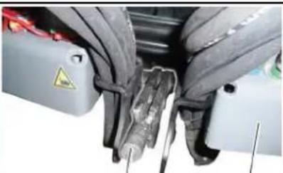
natural_image
Close-up of a mechanical assembly with visible components and mounting brackets (no text or symbols)
②
(1)Tige
natural_image
Industrial robotic arm with yellow plastic components and wiring, no visible text or symbols
natural_image
Mechanical vehicle with two large wheel heads mounted on a yellow support structure (no visible text or symbols)
①Boîte de rangement
natural_image
Close-up of a mechanical assembly with red and silver components, no visible text or symbols
natural_image
Close-up of mechanical components with a numbered annotation pointing to a specific part (no readable text or symbols)
natural_image
Close-up of a mechanical device with multiple connectors and tubing, showing two circled components (no visible text or symbols)
natural_image
Mechanical assembly diagram showing a motor and gears with numbered components (no readable text or symbols)
natural_image
Diagram of a vehicle chassis with two wheels and internal components (no text or symbols)
①Vis 1
②Vis 2
natural_image
3D mechanical assembly diagram showing a robotic arm with labeled parts (1 and 2), no readable text or symbols present.
①Contre-écrou
②Six-pans
natural_image
Mechanical assembly on a pallet jack with numbered parts (1, 2), no visible text or symbols beyond labels
①Palette
natural_image
Mechanical assembly diagram showing a component with numbered parts and an arrow indicating motion (no text or symbols present)
natural_image
Diagram of a vehicle's front wheel assembly showing two wheels with motors and suspension components (no text or labels)
①Vis 1
②Vis 2
natural_image
Mechanical assembly diagram showing a robotic arm with labeled parts (1 and 2), no readable text or symbols present.
①Contre-écrou
②Six-pans
natural_image
Exterior view of a cleaning or cleaning service vehicle with multiple side-mounted sensors (no visible text or symbols)
①Œillet de remorquage
②Boulon de sécurité
①Œillet de remorquage
natural_image
Close-up of mechanical components with no visible text or symbols
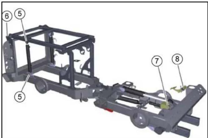
①Tuyau d'aspiration
natural_image
Close-up of a device's internal panel with red tool, showing a hand pressing a button (no text or symbols visible)
natural_image
Top-down view of a military vehicle chassis showing rear engine, chassis panel, and cable connections (no text or symbols visible)
natural_image
Close-up of a mechanical component with an inset showing a close-up view of a component (no visible text or symbols)
natural_image
Technical diagram of a vehicle wheel assembly with labeled parts (1 and 2), showing components like tire, brake caliper, and suspension bracket (no text or symbols beyond labels)
natural_image
Interior view of a vehicle showing a cylindrical device with labeled parts (1 and 2), no visible text or symbols beyond labels.
① Cache
②Fusibles
natural_image
Close-up of a vehicle's wheel rim and tire components, labeled with numbers 1 to 4 indicating parts of the wheel (no text or symbols beyond labels)
2006/42/CE (+2009/127/CE)
2014/30/UE
2000/14/CE
Chairman of the Board of Management

S. Reiser
Director Regulatory Affairs & Certification
71364 Winnenden (Germany)
Winnenden, 2018/07/18
Indice
Istruzioni.... 168
natural_image
Close-up of industrial machinery components with hoses and connectors (no visible text or symbols)
natural_image
Close-up of industrial machinery components with hoses and connectors (no visible text or symbols)
natural_image
Close-up of mechanical components with hoses and connectors, no visible text or symbols
natural_image
Close-up of a red plastic pushpin on a mechanical component, labeled with number 1 (no text or symbols on the object itself)
①Viti
②Copertura
natural_image
Close-up of a black mechanical component with threaded end and protruding shaft (no visible text or symbols)
natural_image
3D technical diagram of a turbocharger assembly with pipes and valves (no text or labels)
natural_image
Black rectangular device with a central display and metallic connectors (no visible text or symbols)
natural_image
Close-up of a black rectangular electronic device with a central display and metallic connectors (no visible text or symbols)
natural_image
Close-up of a vehicle's front panel with visible structural components and a warning light (no text or symbols)
natural_image
Close-up of a black industrial machine component mounted on a wooden floor, with no visible text or symbols.
○ Joystick sinistro
natural_image
Close-up of industrial piping and hoses in two views (① and ④), no visible text or symbols
Chairman of the Board of Management

S. Reiser
Director Regulatory Affairs & Certification
71364 Winnenden (Germania)
Tel.: +49 7195 14-0
Fax: +49 7195 14-2212
Winnenden, 18/07/2017
natural_image
Close-up of mechanical components with no visible text or symbols
natural_image
Close-up of a gray industrial robotic vehicle showing internal components and a numbered annotation (1), no readable text or symbols present.
natural_image
Close-up of industrial machinery components with visible wiring and numbered labels (no readable text or symbols)
natural_image
Close-up of a mechanical assembly with visible components and numbered labels (1, 2), no readable text or symbols beyond labels.
natural_image
Close-up of a gray industrial robotic vehicle showing internal components and a numbered annotation (1), no readable text or symbols present.
natural_image
Industrial robotic arm with yellow safety guard and white components, no visible text or symbols
natural_image
Mechanical vehicle chassis with two large tires mounted on a yellow support frame (no visible text or symbols)
①Leva di bloccaggio
natural_image
Close-up of a mechanical assembly with red and green components, no visible text or symbols
natural_image
Close-up of a mechanical assembly with visible components and a numbered annotation (1), no readable text or symbols present.
①Leva di bloccaggio
natural_image
Close-up of a mechanical device with multiple connectors and tubing, no visible text or symbols
natural_image
Mechanical assembly diagram showing a motor and gears with numbered components (no text or symbols visible)
natural_image
Technical diagram of a vehicle chassis with two wheels and internal components (no text or labels)
①Vite 1
②Vite 2
natural_image
3D mechanical assembly diagram showing a robotic arm with labeled parts (1 and 2), no readable text or symbols present.
natural_image
Mechanical assembly on a pallet with numbered parts (1, 2), no visible text or symbols beyond labels
natural_image
Mechanical assembly diagram showing a motor with labeled parts and a black arrow indicating motion direction (no text or symbols present)
natural_image
Diagram of a bicycle's front wheel assembly showing two wheels with mechanical components (no text or labels)
natural_image
Mechanical assembly diagram showing a rotating component with labeled parts (1 and 2), no readable text or symbols present.
①Controdado
②Esagono
natural_image
Exterior view of a cleaning or cleaning service vehicle with multiple spray gun components (no text or symbols visible)
natural_image
Close-up of mechanical components with no visible text or symbols
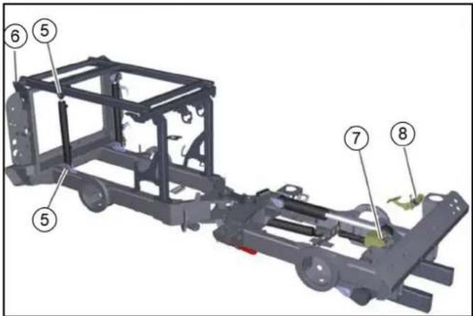
①Dadi di sicurezza
①Biella
natural_image
Close-up of a hand pressing a red tool on a device panel, with no visible text or symbols.
natural_image
Close-up of a mechanical component with an inset showing a close-up view of a component (no visible text or symbols)
①Coperchio
natural_image
Technical diagram of a vehicle's wheel assembly with labeled parts (1 and 2), showing components like tire, brake, and suspension components.
①Dado della ruota
②Ruota
natural_image
Close-up of a mechanical assembly with numbered components (1 and 2), no visible text or symbols.
①Coperchio laterale
②Vano ventola
natural_image
Close-up of a vehicle's wheel rim and tire components, labeled with numbers 1 to 4 indicating different parts (no text or symbols beyond labels)
Chairman of the Board of Management

S. Reiser
Director Regulatory Affairs & Certification
71364 Winnenden (Germany)
Tel.: +49 7195 14-0
Fax: +49 7195 14-2212
Winnenden, 18/07/2018
Interruptor principal
Cabina del conductor
natural_image
Close-up of industrial machinery components with hoses and connectors, no visible text or symbols
natural_image
Close-up of industrial machinery components with coiled cable and labeled parts (no readable text or symbols)
natural_image
Close-up of industrial machinery components with hoses and connectors, no visible text or symbols
Interruptor principal

natural_image
Close-up of mechanical components with hoses and connectors, no visible text or symbols
natural_image
Close-up of a red plastic pushpin inserted into a black mechanical component, with no visible text or symbols.
natural_image
Close-up of a black mechanical component with threaded end and protruding shaft (no visible text or symbols)
① Equipo de barrido
②Boca de aspiración
natural_image
3D mechanical assembly diagram showing internal components with no visible text or symbols
natural_image
Black rectangular device with a central display and metallic connectors (no visible text or symbols)
natural_image
Black rectangular device with a central display and metallic connectors (no visible text or symbols)
natural_image
Mechanical assembly diagram showing a shaft and mounting bracket with numbered components (1, 2, 3), no readable text or symbols present.
natural_image
Close-up of a mechanical component with labeled parts (1, 2, 3), showing internal structure and wiring (no readable text or symbols)
natural_image
Close-up of a black mechanical device with two directional icons and a numbered label (1), no readable text or symbols beyond icons.
natural_image
Close-up of a black industrial machine component with visible wiring and a labeled part (1), mounted on a wooden floor (no text or symbols beyond label)
①Joystick izquierdo
natural_image
Close-up of industrial piping and hoses in two views (① and ④), no visible text or symbols
①Cierre
Chairman of the Board of Management

S. Reiser
Director Regulatory Affairs & Certification
71364 Winnenden (Germany)
Tel.: +49 7195 14-0
Fax: +49 7195 14-2212
Winnenden, 18/07/2017
①Conector de acoplamiento
②Manguito de acoplamiento
③Anillo
natural_image
Close-up of mechanical components with no visible text or symbols
①Apoyo delantero
②Apoyo trasero
natural_image
Close-up of mechanical components with coiled hoses and numbered annotations (1, 2), no readable text or symbols beyond labels
natural_image
Close-up of a car's front suspension system showing valve assembly and labeled component (1), no text or symbols present.
①Conexiones de agua
natural_image
Close-up of industrial machinery components with visible wiring and safety labels (no readable text or symbols)
natural_image
Close-up of a mechanical assembly with visible components and numbered labels (no readable text or symbols)
natural_image
Close-up of a car's front suspension system showing valve assembly and labeled component (1), no readable text or symbols beyond labeling.
①Conexiones de agua
natural_image
Industrial robotic arm with yellow safety guard and white brush, no visible text or symbols
①Brazo de cepillo lateral
②Tope
natural_image
Mechanical vehicle chassis with two large tires mounted on a yellow support structure (no visible text or symbols)
natural_image
Close-up of a mechanical assembly with red and green components, no visible text or symbols
natural_image
Close-up of mechanical components with a numbered annotation pointing to a component (no readable text or symbols)
①Palanca de bloqueo
natural_image
Close-up of a mechanical device with multiple connectors and tubing, showing two circled components (no visible text or symbols)
natural_image
Mechanical assembly diagram showing a shaft and housing with numbered components (no readable text or symbols)
natural_image
Diagram of a vehicle's front wheel assembly showing two wheels and internal components (no text or labels)
natural_image
Mechanical assembly diagram showing a robotic arm with labeled parts (1 and 2), no readable text or symbols present.
natural_image
Yellow manual pallet jack with mechanical components and labeled parts (1, 2), no readable text or symbols beyond labels
natural_image
Mechanical assembly diagram showing a component with numbered parts and an arrow indicating motion (no text or symbols present)
natural_image
Diagram of a bicycle's front wheel assembly showing two wheels with mechanical components (no text or labels)
①Tornillo 1
②Tornillo 2
natural_image
Mechanical assembly diagram showing a conveyor belt system with two numbered components (1 and 2), no visible text or symbols.
① Contratuerca
②Hexágono
natural_image
Side view of a cleaning or cleaning service vehicle with multiple tool tips and no visible text or symbols
natural_image
Close-up of mechanical components with no visible text or symbols
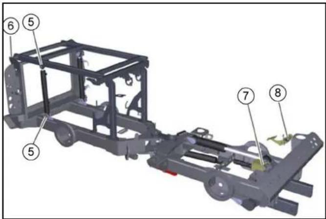
①Vástago del émbolo
natural_image
Close-up of a computer interface showing a hand inserting a red tool into a black socket, with no visible text or symbols.
natural_image
Top-down view of a vehicle chassis showing rear-mounted electronic equipment with labeled components (no text or symbols beyond labels)
natural_image
Close-up of a mechanical component with an inset showing a close-up view of a component (no visible text or symbols)
① Cierre
②Carcasa del filtro de aire
③Tornillo de mariposa
natural_image
Close-up of a vehicle's wheel assembly with labeled parts (1 and 2), showing tire, brake caliper, and suspension components (no text or symbols beyond labels)
①Tuercas de la rueda
②Rueda
natural_image
Close-up of mechanical components with numbered annotations (1 and 2) pointing to features like a metallic ring and brass valve (no readable text or symbols)
①Cierre de bayoneta
natural_image
Close-up of a vehicle's wheel rim and tire components, labeled with numbers 1 to 4 indicating parts of the wheel (no text or symbols beyond labels)
2006/42/CE (+2009/127/CE)
2014/30/UE
2000/14/CE
Chairman of the Board of Management

S. Reiser
Director Regulatory Affairs & Certification
71364 Winnenden (Germany)
Tel.: +49 7195 14-0
Fax: +49 7195 14-2212
Winnenden, 2018/07/18
Índice
Introdução 282
The Ground Truth image displays a single, solid horizontal line. According to Rule 2 (UNDERSCORE & LINE RULES), this is a stylistic or background line, not a placeholder underscore. Therefore, the OCR result must ignore it and output nothing or only meaningful text. The provided OCR content is "\_\_\_\_", which consists of four underscores. This is an incorrect interpretation of the line as a placeholder, violating the rule that stylistic lines must be ignored. The OCR has hallucinated placeholder underscores where none exist in the GT. Hence, the OCR result is inconsistent with the Ground Truth.
ATENÇÃO
Perigo de ferimentos
The Ground Truth image displays a single, solid horizontal line. According to Rule 2 (UNDERSCORE & LINE RULES), this is a stylistic or background line, not a placeholder underscore. Therefore, the OCR result must ignore it and output nothing or only meaningful text. The provided OCR content is "\_\_\_\_", which consists of four underscores. This is an incorrect interpretation of the line as a placeholder, violating the rule that stylistic lines must be ignored. The OCR has hallucinated placeholder underscores where none exist in the GT. Hence, the OCR result is inconsistent with the Ground Truth.
△PERIGO
Perigo de queda
Interruptor principal
natural_image
Close-up of industrial machinery components with hoses and connectors (no visible text or symbols)
natural_image
Close-up of industrial machinery components with coiled cable and labeled parts (no readable text or symbols)
natural_image
Industrial machinery component with hoses and connectors, labeled parts ① and ② (no readable text or symbols)
Interruptor principal

①Interruptor principal
②Bateria desligada
③Bateria ligada
natural_image
Close-up of mechanical components with hoses and connectors, no visible text or symbols
natural_image
Close-up of a red plastic pushpin inserted into a black mechanical component, with no visible text or symbols.
natural_image
Close-up of a black mechanical component with threaded end and protruding shaft (no visible text or symbols)
natural_image
Close-up of a black mechanical component with two directional icons (left and right) and a numbered label (1), no readable text or symbols beyond icons.
natural_image
3D mechanical assembly diagram showing internal pipes and tubing (no text or symbols)
natural_image
Black rectangular device with a central lens and metallic connectors (no visible text or symbols)
natural_image
Close-up of a black rectangular electronic device with a central display and metallic connectors (no visible text or symbols)
①Interruptor principal
②Bateria desligada
③Bateria ligada
natural_image
Close-up of a vehicle's front panel with visible structural components and a warning light (no text or symbols)
natural_image
Close-up of a black mechanical component with two icons and a numbered label (1), no readable text or symbols beyond the icon labels.
natural_image
Close-up of a black industrial machine with coiled tubing and a labeled component (①), mounted on a wooden floor (no visible text or symbols)
natural_image
Close-up of industrial piping and valves in two views: left shows mechanical assembly with hoses and fittings, right shows internal equipment with tubing (no visible text or symbols)
①Fecho
Chairman of the Board of Management

S. Reiser
Director Regulatory Affairs & Certification
71364 Winnenden (Germany)
Tel.: +49 7195 14-0
Fax: +49 7195 14-2212
Winnenden, 18/07/2017
natural_image
Close-up of mechanical components with no visible text or symbols
① Suportes de estacionamento dianteiros
② Suportes de estacionamento traseiros
natural_image
Close-up of a gray industrial vehicle showing internal components and a numbered annotation (1), no readable text or symbols present.
①Ligações de água
natural_image
Close-up of industrial machinery components with visible wiring and numbered labels (no readable text or symbols)
natural_image
Close-up of a mechanical assembly with visible components and numbered labels (1, 2), no readable text or symbols beyond labels.
natural_image
Close-up of a car's front suspension system showing valve assembly and component alignment (no text or symbols visible)
①Ligações de água
① Suportes de estacionamento dianteiros
(1)Barra
natural_image
Industrial robotic arm with yellow and white components, connected to a control panel with cable and wiring (no visible text or symbols)
natural_image
Mechanical vehicle with two large wheel heads mounted on a yellow support structure (no visible text or symbols)
natural_image
Close-up of a mechanical cleaning or cleaning device with labeled parts (1, 2), showing brush and mesh components without any readable text or symbols.
natural_image
Close-up of industrial machinery components with no visible text or symbols
natural_image
Close-up of mechanical components with a numbered annotation pointing to a tool (no readable text or symbols)
natural_image
Close-up of a mechanical device with multiple connectors and tubing, showing internal components (no visible text or symbols)
natural_image
Mechanical assembly diagram showing a shaft and housing with numbered components (no readable text or symbols)
natural_image
Diagram of a vehicle chassis with two wheels and internal components (no text or symbols)
①Parafuso 1
②Parafuso 2
natural_image
3D mechanical assembly diagram showing a robotic arm with labeled parts (1 and 2), no readable text or symbols present.
① Contraporca
②Sextavado
natural_image
Mechanical assembly on a pallet jack with numbered parts (1, 2), no visible text or symbols beyond labels
①Palette
②Sistema de varredura
- Deslocar o carro elevador por baixo da palete com o sistema de varredura posicionado.
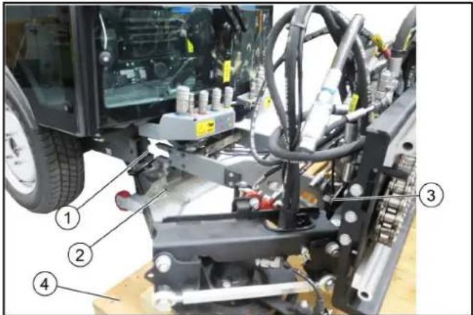
natural_image
Mechanical assembly diagram showing a component with numbered parts and an arrow indicating motion (no text or symbols present)
①Pernos
②Contrapino de mola
natural_image
Diagram of a bicycle's front wheel assembly showing two wheels with brake calipers and suspension components (no text or labels)
①Parafuso 1
②Parafuso 2
natural_image
Mechanical assembly diagram showing a rotating conveyor belt system with labeled components (no text or symbols present)
natural_image
Exterior view of a cleaning or cleaning service vehicle with multiple spray stations and control panels (no text or symbols visible)
natural_image
Close-up of mechanical components with no visible text or symbols
①Válvulas bypass
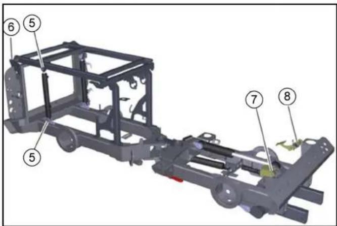
①Pinos de segurança
②Contrapino de segurança
natural_image
Close-up of a computer interface showing a hand inserting a red tool into the button, with no visible text or symbols.
natural_image
Close-up of a mechanical component with an inset showing a close-up view of a component (no visible text or symbols)
natural_image
Technical diagram of a vehicle's wheel assembly with labeled parts (1 and 2), showing components like tire, brake, and suspension components.
① Bocal de enchimento
natural_image
Close-up of a mechanical engine component with hoses and springs (no visible text or symbols)
②
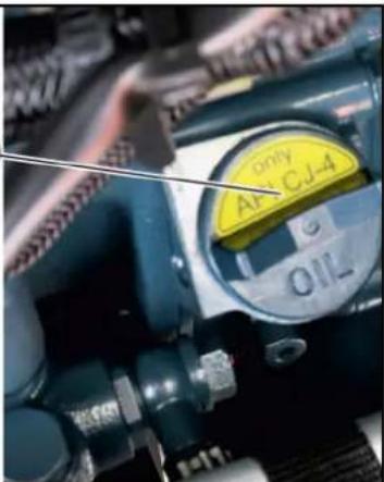
①Parafusos laterais
②Simetria da vassoura
③Vassoura lateral
④Porcas (4x)
⑤Parafusos traseiros
-
Levantar a vassoura lateral.
-
Soltar as porcas.
-
Retirar a vassoura lateral.
-
Colocar e aparafusar as novas vassouras.
Ajustar a simetria da vassoura
①Grelha do difusor
natural_image
Interior view of a vehicle showing a cylindrical device with labeled parts (1 and 2), no visible text or symbols beyond labels.
①Fecho da baioneta
②Válvula da água de reciclagem
③Depósito de detritos
1. Esvaziar o depósito de detritos.
2. Levantar o depósito de detritos.
3. Abrir o fecho da baioneta.
4. Remover a válvula.
5. Limpar a válvula sob água corrente.
6. Colocar a válvula.
7. Fechar o fecho da baioneta.
Fusíveis
①Cobertura
②Fusíveis
(A) - (E) Parafusos SW 8
natural_image
Close-up of a vehicle's rear wheel rim and tire, showing numbered components (no text or symbols)
2006/42/CE (+2009/127/CE)
2014/30/UE
2000/14/CE
Chairman of the Board of Management

S. Reiser
Director Regulatory Affairs & Certification
Winnenden, 18/07/2018
Inhoud
①Zuigmond/frontkrachttiller
②Rechter en linker bezemarm samen optillen
③Zijbezems inzwenken
④Zijbezems uitzwenken
⑤Hydraulische PTO (80 l/min)
⑥Hydraulische PTO (40 l/min)
natural_image
Close-up of industrial machinery components with hoses and connectors, no visible text or symbols
natural_image
Close-up of industrial machinery components with coiled cable and labeled parts (no readable text or symbols)
natural_image
Close-up of industrial machinery components with hoses and connectors, no visible text or symbols
natural_image
Close-up of mechanical components with hoses and connectors, no visible text or symbols
①Schuifvenster
② Contactsleutel
③Deuropener
natural_image
Close-up of a red plastic pushpin on a mechanical component, labeled with number 1 (no text or symbols on the object itself)
①Extra contactdoos 12 V
②Vuilreservoir/aanbouwframe optillen
③ Vuilreservoir/aanbouwframe neerlaten
① Functietoetsen
natural_image
Close-up of a black mechanical component with threaded end and protruding shaft (no visible text or symbols)
①Rijpedaal
②Rempedaal
③Pedaal bezemaanpersdruk/bezemtoerental
Rijpedaal
LET OP
①Veeginrichting
②Zuigmond
③Vuilreservoir
①Zuigmond
②Recyclingwaterslang
③Zuigslang
④Vuilcontainer
natural_image
3D mechanical assembly diagram showing internal components of a turbocharger or compressor (no text or labels visible)
①Bezem en schop
②Hogedrukreiniger
③Vuilkrasser
Instructie
natural_image
Black rectangular device with a central display showing metallic components and small metallic connectors (no visible text or symbols)
natural_image
Black rectangular device with a central display showing metallic components and small metallic connectors (no visible text or symbols)
natural_image
Mechanical assembly diagram showing a shaft and mounting bracket with numbered components (1, 2, 3), no readable text or symbols present.
①Klemhendel hoogteverstelling stuurwiel
②Hendel hellingsverstelling stuurwiel
natural_image
Close-up of a mechanical component with labeled parts (1, 2, 3), showing internal structure and no readable text or symbols.
①Watervulaansluiting (GEKA)
②Bekleding, rechts
③Waterafvoer (vulhoogte)
natural_image
Close-up of a black mechanical component with two icons and a numbered label (1), no readable text or symbols beyond the icon design.
De motor is in nullast.
natural_image
Close-up of a black industrial machine component mounted on a wooden floor, with no visible text or symbols.
①Joystick links
2-bezemsysteem: Bezemarmen neerlaten en bezem aan
3-bezemsysteem (optie): 3e bezem neerlaten/optillen en be-
zem in/uit
②Joystick rechts
Bij optioneel 3-bezemsysteem: Achterste 2 bezems neerla-
ten/optillen en bezem in/uit
Bezem in- en uitzwenken
③Zuigmond optillen/neerlaten
④Hydraulisch systeem aan/uit
⑤Bij optioneel 3-bezemsysteem: Bezemomkering 3e bezem
⑥ Bij optioneel 3-bezemsysteem: Knikken/rollen 3e bezem Instructie
①Extra contactdoos 12 V
②Vuilreservoir/aanbouwframe optillen
③Vuilreservoir/aanbouwframe neerlaten
natural_image
Close-up of industrial piping and hoses in two views: one with coiled tubing and fittings, the other with coiled tubing and wiring (no visible text or symbols)
①Sluiting

H. Jenner
Chairman of the Board of Management

S. Reiser
Director Regulatory Affairs & Certification
71364 Winnenden (Germany)
Tel.: +49 7195 14-0
Fax: +49 7195 14-2212
Winnenden, 2017/07/18
①Koppelingsstekker
②Koppelingsmof
③Ring
natural_image
Close-up of mechanical components with no visible text or symbols
①Vergrendelingshendel
②Spanmoer
①Voorste steun
② Achterste steun
①Vuilreservoir
②Borgbout
③Borgclip
④Frame
⑤Hydraulische aansluiting
natural_image
Close-up of a car's front and side view showing internal components, with a numbered annotation pointing to a component (no text or symbols present)
①Wateraansluitingen
natural_image
Close-up of a mechanical assembly with visible components and numbered labels (1, 2), no readable text or symbols beyond labels.
①Zuigslang
②Vuilreservoir
natural_image
Close-up of a mechanical assembly with visible components and numbered annotations (no readable text or symbols)
①Zuigslang
②Vuilreservoir
natural_image
Close-up of a gray industrial robotic vehicle showing internal components and a numbered annotation (1), no readable text or symbols present.
①Wateraansluitingen
①Hendelstand veegsysteem ontgrendeld
②Hendelstand veegsysteem vergrendeld
③Voertuigfront
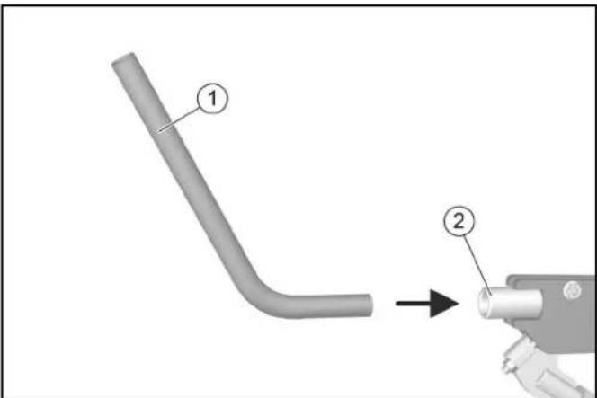
(1)Stang
(2)Vergrendelingshendel
natural_image
Industrial robotic arm with yellow and gray components, no visible text or symbols
natural_image
Mechanical vehicle chassis with two large wheels mounted on a yellow support structure (no visible text or symbols)
natural_image
Close-up of a mechanical cleaning or cleaning device with labeled parts (1, 2), showing brush and mesh components without any readable text or symbols.
natural_image
Close-up of a mechanical assembly with red and silver components, no visible text or symbols
natural_image
Close-up of a mechanical assembly with pipes and a tool, no visible text or symbols
natural_image
Close-up of a mechanical device with multiple connectors and tubing, showing two circled components (no visible text or symbols)
natural_image
Mechanical assembly diagram showing a shaft and housing with numbered components (1, 2), no readable text or symbols present.
①Opname wisselwagen
②Frame frontkrachttiller
natural_image
Technical diagram of a vehicle chassis with two large wheels and internal components (no text or symbols)
natural_image
3D mechanical assembly diagram showing a robotic arm with labeled parts (1 and 2), no readable text or symbols present.
natural_image
Industrial robotic pallet with labeled parts (1, 2), no visible text or symbols on the machinery itself.
①Pallet
②Veegsysteem
①PTO borstels
②Frontbezem hellen / rollen
③Frontbezem optillen / neerlaten
④Lekolie
⑤Zuigmond / veegbezem zwenken
⑥Veegbezem optillen / neerlaten
⑦Frontbezem zwenken
⑧PTO 80 l/min
⑨PTO borstels
⑩ Wateraansluiting rechts
⑪ Wateraansluiting links
natural_image
Mechanical assembly diagram showing a motor with labeled parts (1 and 2), no readable text or symbols present.
①Bout
②Veerstekker
natural_image
Diagram of a vehicle's front wheel assembly showing two wheels with motors and suspension components (no text or labels)
①Schroef 1
② Schroef 2
natural_image
Mechanical assembly diagram showing a conveyor belt system with two labeled components (1 and 2), no readable text or symbols present.
①Contramoer
②Zeskant
natural_image
Mechanical assembly diagram showing a shaft and frame components with numbered parts (1, 2, 3), no readable text or symbols present.
natural_image
Exterior view of a modern cleaning or cleaning service vehicle with visible spray equipment and control panel (no text or symbols)
①Sleepoog
natural_image
Close-up of mechanical components with no visible text or symbols
①Bypassventielen
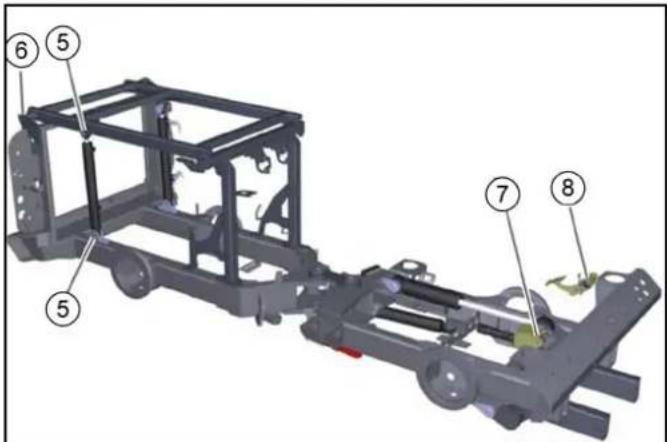
| Smeerpunt Aantal | smeer-punten | Smeerin-terval |
| 1 As | hefarm bezemkop telkens 1 Om de 8 h | | |
| 2 As | hefarm cilinder telkens 1 Om de 8 h | | |
| 3 As | hefarm scharnierlager telkens 1 Om de 8 h | | |
| 4 As | cilinder scharnierlager telkens 1 Om de 8 h | | |
LET OP
Functiestoringen
①Borgbout
②Borgclip
①Zuigerstang
②Borgclip
③Borgsteun
①Zuigslang
natural_image
Close-up of a computer interface showing a hand inserting a red tool into the button, with no visible text or symbols.
①Deksel
②Expansievat
③Markering bovenste vulniveau
④Markering onderste vulniveau
①Hydraulische vloeistof
②Oliepeil MIN
③Oliepeil MAX
natural_image
Close-up of a mechanical component with an inset showing a close-up view of a component (no visible text or symbols)
① Vergrendeling
②Luchtfilterbehuizing
③Vleugelschroef
① Afdekking
②Stoffilter
Instructie
natural_image
Technical diagram of a vehicle's wheel assembly with labeled parts (1 and 2), showing components like tire, brake, and suspension components.
①Wielmoeren
②Wiel
①Oliepeilstok
②Afdekking
(1)Bevestiging brandstoftank
(2)Brandstoftank
(1)Vuldop
(2)Vuldop MC 130 advanced plus
①Diffusorrooster
②Vuilwaterzeef
③Vuilreservoir
①Bajonetsluiting
②Ventiel recyclingwater
③Vuilreservoir
①Afdekking
②Zekeringen
natural_image
Close-up of a vehicle's wheel rim and tire components, labeled with numbers 1 to 4 indicating parts of the wheel (no text or symbols beyond labels)
Product: Veegmachine
Type: PF-D
Chairman of the Board of Management

S. Reiser
Director Regulatory Affairs & Certification
71364 Winnenden (Germany)
Tel.: +49 7195 14-0
Fax: +49 7195 14-2212
Winnenden, 2018/07/18
Περιεχόμενα
Εισαγωγή 394
Συστήματα ασφαλείας
natural_image
Close-up of industrial machinery components with hoses and connectors, no visible text or symbols
natural_image
Close-up of industrial machinery components with coiled cable and labeled parts (no readable text or symbols)
natural_image
Close-up of industrial machinery components with hoses and connectors, no visible text or symbols
natural_image
Close-up of a mechanical component with hoses and a metallic clip, no visible text or symbols
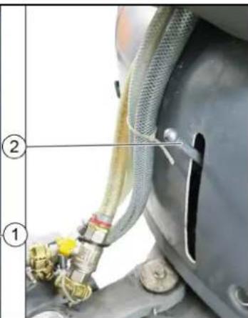
natural_image
Close-up of a red plastic pushpin inserted into a black mechanical component, with no visible text or symbols.
①Βίδες
②Κάλυμμα
natural_image
Close-up of a black mechanical component with threaded shaft and housing (no visible text or symbols)
natural_image
3D mechanical assembly diagram showing internal components of a turbocharger or compressor (no text or labels visible)
natural_image
Black rectangular device with a central display and metallic connectors (no visible text or symbols)
natural_image
Close-up of a black rectangular electronic device with a central display and metallic connectors (no visible text or symbols)
natural_image
Mechanical assembly diagram showing a shaft and mounting bracket with numbered components (1, 2, 3), no readable text or symbols present.
natural_image
Close-up of a mechanical component with labeled parts (1, 2, 3), showing internal components and wiring (no readable text or symbols)
natural_image
Close-up of a black industrial machine component with visible wiring and a numbered label (1) on the floor, no readable text or symbols.
natural_image
Industrial equipment setup with hoses and tubing, no visible text or symbols
①Πώμα
Chairman of the Board of Management

S. Reiser
Director Regulatory Affairs & Certification
71364 Winnenden (Germany)
Tηλ.: +49 7195 14-0
Φαξ: +49 7195 14-2212
Winnenden, 2017/07/18
natural_image
Close-up of mechanical components with no visible text or symbols
natural_image
Close-up of a gray industrial robotic vehicle showing internal components and a numbered annotation (1), no readable text or symbols present.
①Συνδέσεις νερού
natural_image
Close-up of a mechanical assembly with visible components and numbered labels (1 and 2), no readable text or symbols beyond labels.
natural_image
Close-up of industrial machinery components with visible wiring and numbered labels (no readable text or symbols)
natural_image
Close-up of a gray industrial vehicle's side view showing internal components and a numbered annotation (1), no readable text or symbols present.
(1)Ράβδος
(2)Μοχλός ασφάλισης
natural_image
Industrial robotic arm with yellow plastic components and white wiring, no visible text or symbols
natural_image
Mechanical vehicle chassis with two large wheel heads and a yellow support structure (no visible text or symbols)
natural_image
Close-up of a mechanical assembly with red and green components, no visible text or symbols
natural_image
Close-up of mechanical components with a numbered annotation pointing to a tool (no readable text or symbols)
①Μοχλός ασφάλισης
natural_image
Close-up of a mechanical device with multiple connectors and tubing, no visible text or symbols
natural_image
Mechanical assembly diagram showing a shaft and housing with numbered annotations (1, 2) indicating specific components (no readable text or symbols beyond labels)
natural_image
Diagram of a vehicle chassis with two wheels and internal components (no text or symbols)
natural_image
3D mechanical assembly diagram showing a robotic arm with two labeled parts (1 and 2), no readable text or symbols present.
natural_image
Mechanical assembly on a pallet jack with numbered parts (1, 2), no visible text or symbols beyond labels
①Παλέτα
②Σύστημα σάρωσης
natural_image
Mechanical assembly diagram showing a mechanical component with numbered parts and an arrow indicating a specific connection (no text or symbols present)
natural_image
Diagram of a bicycle's front wheel assembly showing two wheels with mechanical components (no text or labels)
①Bíða 1
②Bíða 2
natural_image
Mechanical assembly diagram showing a conveyor belt system with two numbered components (1 and 2), no visible text or symbols.
natural_image
Exterior view of a cleaning or cleaning service vehicle with multiple spray sensors (no text or symbols visible)
①Κρίκος ρυμούλκησης
natural_image
Close-up of mechanical components with no visible text or symbols
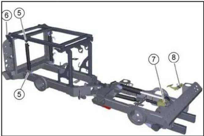
①Ράβδος εμβόλου
②Κοπίλια ασφάλισης
③Στήριγμα ασφάλισης
natural_image
Close-up of a computer interface showing a hand inserting a red tool into the button, with no visible text or symbols.
natural_image
Close-up of a mechanical component with an inset showing a close-up view of a component (no visible text or symbols)
natural_image
Mechanical assembly diagram showing a tire and brake component with numbered parts (1 and 2), no text or symbols present.
① Παξιμάδια τροχού
②Τροχός
①Στόμιο πλήρωσης
natural_image
Close-up of a mechanical engine component with hoses and valves (no visible text or symbols)
②
①Πλέγμα σκέδασης
① Πλευρικό κάλυμμα
②Χώρος φυσητήρα
①Κάλυμμα
②Ασφάλειες
①Αντλία χειρός
(A) - (E) Bíðες SW 8
(F) Ρικνός κοχλίας
natural_image
Close-up of a vehicle's wheel rim and tire components, labeled with numbers 1 to 4 indicating different parts (no text or symbols beyond labels)
①Ελαστικά, στενά
Chairman of the Board of Management

S. Reiser
Director Regulatory Affairs & Certification
71364 Winnenden (Germany)
Tηλ.: +49 7195 14-0
Φαξ: +49 7195 14-2212
Winnenden, 18/07/2018

natural_image
Black silhouette of a hand giving a thumbs-up gesture (no text or symbols)
THANK YOU!
MERCI! DANKE! iGRACIAS!
Registrieren Sie Ihr Produkt und profitieren Sie von vielen Vorteilen.
Register your product and benefit from many advantages.
Enregistrez votre produit et bénéficier de nombreux avantages.
Registre su producto y aproveche de muchas ventajas.
www.kaercher.com/welcome

Bewerten Sie Ihr Produkt und sagen Sie uns Ihre Meinung.
Rate your product and tell us your opinion.
Évaluer votre produit et dites-nous votre opinion.
Reseñe su producto y díganos su opinión.

natural_image
Icon showing a gear and wrench, no text or symbols present
www.kaercher.com/dealersearch
Alfred Kärcher SE & Co. KG
Alfred-Kärcher-Str. 28-40
71364 Winnenden (Germany)
Tel.: +49 7195 14-0
Fax: +49 7195 14-2212