
IPCA63500 - Security alarm ABUS - Free user manual and instructions
Find the device manual for free IPCA63500 ABUS in PDF.
| Product Type | 8-zone wired expansion module |
| Brand | ABUS |
| Model | IPCA63500 |
| Category | Security alarm |
| Dimensions (H x W x D) | 220 mm x 135 mm x 45 mm |
| Weight | 330 g |
| Power supply | 12 V DC, consumption 60 mA (max. 310 mA with speaker at maximum volume) |
| Number of zones | 8 zones (NC or FSL with anti-masking) |
| Programmable outputs | 1 negative switching output, 1 positive switching output, 100 mA max at 12 V DC |
| Main functions | Addition of 8 wired zones and 2 programmable outputs, connection of additional detectors and speakers |
| Operating temperature | -10 °C to 55 °C |
| Maximum humidity | 96% |
| Maximum bus distance | 1 km |
| Maintenance and cleaning | Disconnect power before cleaning. Use a dry, lint-free cloth. |
| Security | Tamper switch, plug-in jumper for tamper deactivation |
| Spare parts and repairability | Spare parts available from the manufacturer. Repair by a qualified professional. |
| General information | Wired expansion compatible with ABUS control panels. Address adjustable via jumper. |
Frequently Asked Questions - IPCA63500 ABUS
User questions about IPCA63500 ABUS
0 question about this device. Answer the ones you know or ask your own.
Ask a new question about this device
Download the instructions for your Security alarm in PDF format for free! Find your manual IPCA63500 - ABUS and take your electronic device back in hand. On this page are published all the documents necessary for the use of your device. IPCA63500 by ABUS.
USER MANUAL IPCA63500 ABUS
8-Zone Wired Extension
Installation Instructions (UK) 7
Installation Instructions (FR) 12
Installatie-instructions (NL) 17
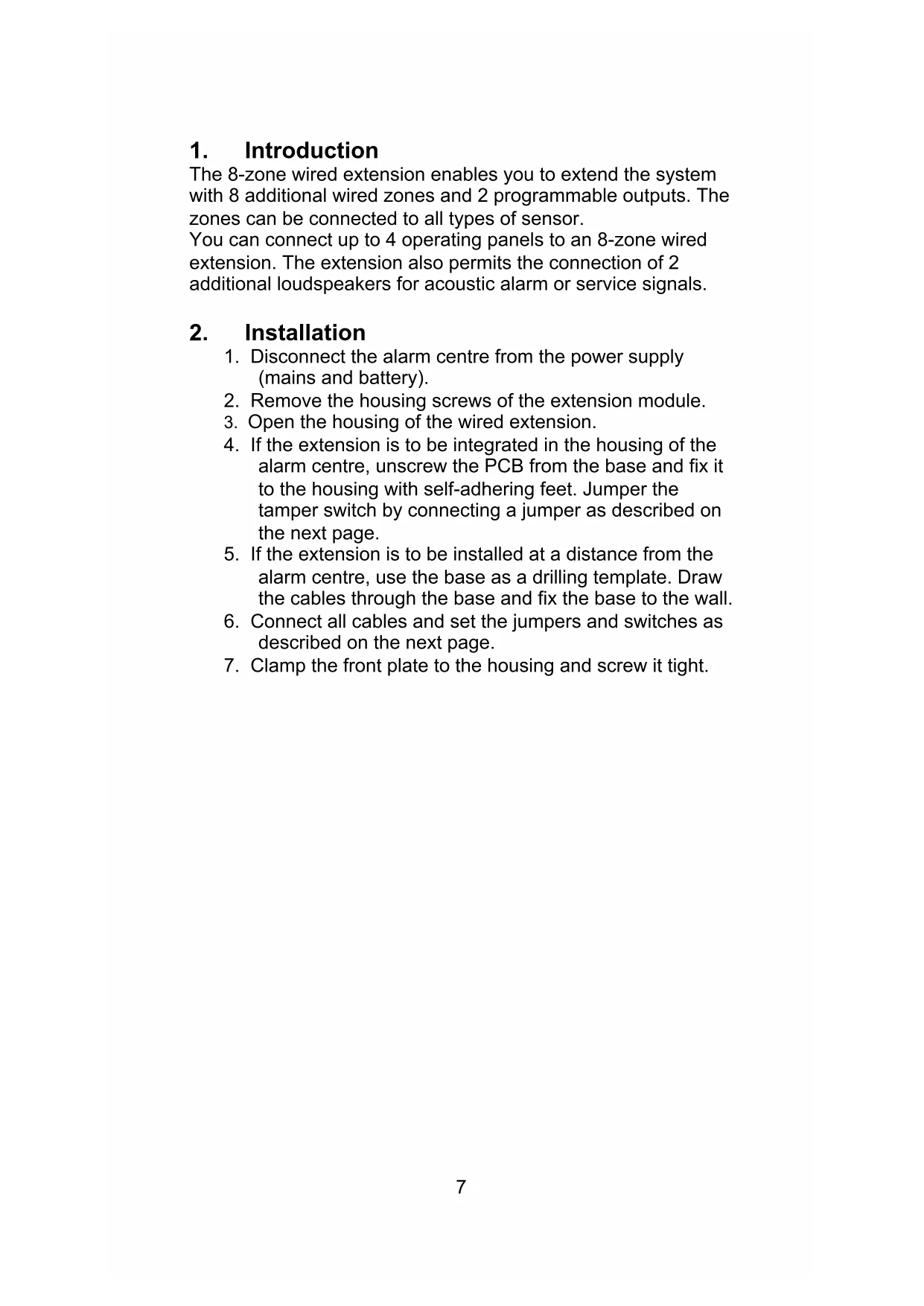
The 8-zone wired extension enables you to extend the system with 8 additional wired zones and 2 programmable outputs. The zones can be connected to all types of sensor.
You can connect up to 4 operating panels to an 8-zone wired extension. The extension also permits the connection of 2 additional loudspeakers for acoustic alarm or service signals.
2. Installation
- Disconnect the alarm centre from the power supply (mains and battery).
- Remove the housing screws of the extension module.
- Open the housing of the wired extension.
- If the extension is to be integrated in the housing of the alarm centre, unscrew the PCB from the base and fix it to the housing with self-adhering feet. Jumper the tamper switch by connecting a jumper as described on the next page.
- If the extension is to be installed at a distance from the alarm centre, use the base as a drilling template. Draw the cables through the base and fix the base to the wall.
- Connect all cables and set the jumpers and switches as described on the next page.
- Clamp the front plate to the housing and screw it tight.
3. Components and Wiring
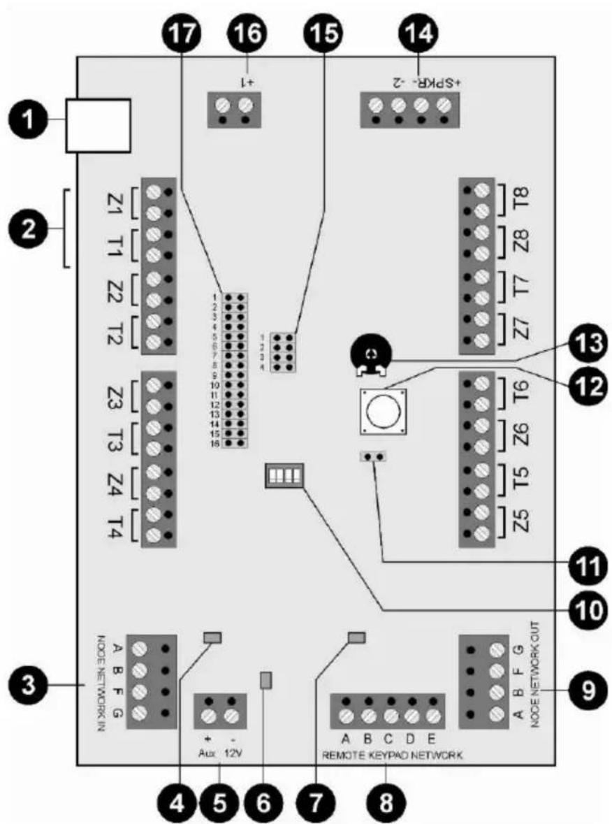
1.) Not used
2.) Zone wiring
You can connect a sensor using one of the following methods. The contacts of the sensors are usually NC (normally closed); if you want NO (normally open), you have to invert the corresponding zones.
Important: If the sensor's voltage supply is to flow via the extension, two extra leads are needed for the connections to connectors A (+12 V DC) and B (0V).
NC wiring
Also known as CCL wiring
FSL wiring (DEOL)
Enables individual monitoring of a wire tamper (see Installation Instructions).
Anti-masking wiring:
If the sensor has the anti-mask attribute, three resistors can monitor all states (OK, alarm, tamper, masked). The zone can be programmed just like any other zone (e.g. "Normal Alarm"), but it must be given the "Masking" attribute. Important: For wiring examples, see the Installation Instructions.
3.) Bus input
Normally an 8 × 0.22mm^2 alarm cable is used. Use screened cables in areas with interference frequencies (see also Installation Instructions).
Important: The maximum distance to the furthest extension must not exceed 1km.
Important: The voltage supply on the extensions must not fall below 10.5V DC (recommendation: min. 12V). If the voltage is too low, duplicate the voltage leads with remaining cables or use an additional voltage supply.
The first extension to the bus is connected to the alarm centre via the NODE NETWORK IN connector (bus input). Each successive extension is connected to NODE NETWORK OUT (bus output) of the previous extension.
4.) AUX error LED
Lights when the fuse blows.
5.) AUX connector
Additional voltage connector for supplying external sensors and outputs.
6.) Power LED:
Lights when the fuse blows.
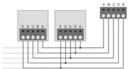
8.) Connecting operating panels (optional)
The voltage supply on the operating panels must not fall below 10.5V DC (recommendation: min. 12V). If the voltage is too low, duplicate the voltage leads with remaining cables or use an additional voltage supply.
9.) Bus output
For connecting further extension modules to the bus.
10.)Notused
All dip-switches must be switched to "OFF".
11.)Tamper jumper
If the jumper is closed, the lid tamper of the extension module is switched off.
12.)Tamper contact
13.)Volume potentiometer
For adjusting the volume of external loudspeakers
14.) Connecting loudspeakers (optional)
Up to 2 external 16 Ohm loudspeakers can be connected in series. The loudspeakers can be adjusted by the potentiometer on the PCB.
Important: If you connect an external loudspeaker, you should connect an extra voltage supply to the 8-zone wired extension.
Output (-2)
In the factory setting, the relay switches from 12 V DCto 0V when the output is activated. The maximum current is 100mA . This output can be inverted during programming if necessary.
15.)JP4
The jumper must be set to Position 3.
16.)Output (+1)
In the factory setting, the relay switches from 12 V DCto 0V when the output is activated. The maximum current is 100mA . This output can be inverted during programming if necessary.
17.) Address of 8-zone wired extension
- Set the jumper to the position matching the extension.
- Important: Make sure that an address is not used more than once on a bus.
4. Technical data
| Power consumption | 60 mA max. at 12 V DC; 310 mA max. with loudspeaker at full volume |
| Zones | 8 zones; NC or FSL with anti-masking |
| Outputs | 1 output negatively switching, 1 output positively switching; 100mA max. at 12 V DC |
| Dimensions | 220mm x 135mm x 45mm (HxWxD) |
| Weight 330g | |
| Ambient operating temperature | -10° to 55°C |
| Ambient operating humidity | Max. 96% |
1. Introduction
Anti-masking-bedrading:


- 8-Zone Wired Extension
- Installation
- Components and Wiring
- FSL wiring (DEOL)
- Anti-masking wiring:
- 3.) Bus input
- 4.) AUX error LED
- 5.) AUX connector
- 6.) Power LED:
- 8.) Connecting operating panels (optional)
- 9.) Bus output
- 10.)Notused
- 11.)Tamper jumper
- 12.)Tamper contact
- 13.)Volume potentiometer
- 14.) Connecting loudspeakers (optional)
- Output (-2)
- 15.)JP4
- 16.)Output (+1)
- 17.) Address of 8-zone wired extension
- Technical data
- Introduction
- Anti-masking-bedrading:
Brand : ABUS
Model : IPCA63500
Category : Security alarm