
MagicWatch MWE890 - Car accessory WAECO - Free user manual and instructions
Find the device manual for free MagicWatch MWE890 WAECO in PDF.
| Product Type | Ultrasonic Parking Aid |
| Brand | Waeco |
| Model | MagicWatch MWE890 |
| Detection Zone | Vehicle front, approx. 0.35 m to 0.75 m |
| Ultrasound Frequency | 40 kHz |
| Supply Voltage | 10 – 24 V |
| Current Consumption | 120 mA max. |
| Operating Temperature | -25 °C to +70 °C |
| Certification | E8 030117 |
| Number of Sensors | 4 |
| Audible Signal | Beeps (frequency varies with distance) |
| Visual Signal | Built-in speaker; optional display (ref. 9101500045) |
| Fixed Object Suppression | Yes, for towbar |
| Sensitivity Adjustment | 3 levels (low, medium, high) |
| Automatic Deactivation | Above 15 km/h (if speed signal connected) |
| Delivery Contents | 4 sensors, control electronics, cables, jumper, mounting kit, 21.5 mm drill bit |
| Painting of Sensors | Possible, recommended by a garage |
| Maintenance | Clean sensors (dirt, ice) |
| Spare Parts Available | Sensors, cables, display, external button |
| Repairability | Possible replacement of sensors and electronics |
Frequently Asked Questions - MagicWatch MWE890 WAECO
User questions about MagicWatch MWE890 WAECO
0 question about this device. Answer the ones you know or ask your own.
Ask a new question about this device
Download the instructions for your Car accessory in PDF format for free! Find your manual MagicWatch MWE890 - WAECO and take your electronic device back in hand. On this page are published all the documents necessary for the use of your device. MagicWatch MWE890 by WAECO.
USER MANUAL MagicWatch MWE890 WAECO
Installation and Operating Manual
FR 29 Parking aid
Installation and Operating Manual
Please read this instruction manual carefully before installation and first use, and store it in a safe place. If you pass on the product to another person, hand over this instruction manual along with it.
Contents
1 Safety and installation instructions. 17
2 Scope of delivery 18
3 Intended use 19
4 Instructions before installation 19
5Fitting the parking aid. 20
6 Connecting the parking aid 20
7 Detection range 22
8 Setting the system 22
9 Performing a functional test 24
10 Using the parking aid 25
11 Troubleshooting 26
12 Guarantee 27
13 Disposal 28
14 Technical data 28
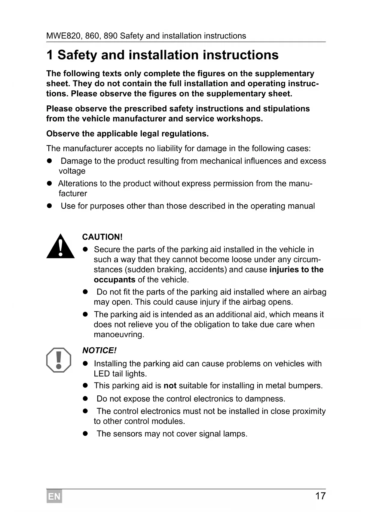
1 Safety and installation instructions
The following texts only complete the figures on the supplementary sheet. They do not contain the full installation and operating instructions. Please observe the figures on the supplementary sheet.
Please observe the prescribed safety instructions and stipulations from the vehicle manufacturer and service workshops.
Observe the applicable legal regulations.
The manufacturer accepts no liability for damage in the following cases:
- Damage to the product resulting from mechanical influences and excess voltage
- Alterations to the product without express permission from the manufacturer
- Use for purposes other than those described in the operating manual

CAUTION!
- Secure the parts of the parking aid installed in the vehicle in such a way that they cannot become loose under any circumstances (sudden braking, accidents) and cause injuries to the occupants of the vehicle.
- Do not fit the parts of the parking aid installed where an airbag may open. This could cause injury if the airbag opens.
- The parking aid is intended as an additional aid, which means it does not relieve you of the obligation to take due care when manoeuvring.

NOTICE!
- Installing the parking aid can cause problems on vehicles with LED tail lights.
- This parking aid is not suitable for installing in metal bumpers.
- Do not expose the control electronics to dampness.
-
The control electronics must not be installed in close proximity to other control modules.
The sensors may not cover signal lamps. -
When fitting the sensors, make sure there are no objects fixed to the vehicle that are in the detection range of the sensors. Displaying fixed objects, such as trailer hitches, can be suppressed.
- Apply a small amount of grease inside the sensor plug connections.
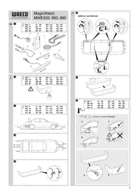
2 Scope of delivery
See fig. 1
| No. Quantity Designation Item no. | |
| 1 4 Ultrasonic sensors 9101500043 | |
| 2 1 Control electronics | |
| MWE 820 | 9101500044 |
| MWE 860 | 9101500046 |
| MWE 890 | 9101500047 |
| 3 1 Loudspeaker 9101500051 | |
| 4 1 Control electronics connection cable | |
| 5 4 Sensors connection cable | |
| 6 1 Fastening material | |
| 7 1 Core bit 21,5 mm | |
| 8 1 Display (MWE860 only) 9101500045 | |
2.1 Accessories
Available as accessories (not included in the scope of delivery):
| Designation Item no. | |
| Punching tool 22 mm 9101500024 | |
| External button (MWE890 only) | 9101500049 |
| Display (MWE890 only) | 9101500045 |
| Extension cable for display, 5 m (MWE860, 890 only) | 9101500053 |
| Connection cable for sensor, 250 cm (MWE820, 860 only) | 9101500048 |
| Connection cable for sensor, 450 cm (MWE890 only) | 9101500050 |
3 Intended use
Magic Watch is an ultrasonic parking aid. It monitors space when manoeuvring
MWE820, 860: behind the vehicle
MWE890: in front of the vehicle
It provides an audible and visual warning signal for any obstacles it detects.
Magic Watch is designed for installation in cars.
4 Instructions before installation
4.1 Determining the place of installation for the sensors
See fig. 3 to fig. 6

NOTE
The sensors must be correctly aligned for the device to work properly.
If these point to the ground, irregularities and bumps on the surface may be interpreted as obstacles. If they point too far up, obstacles will not be detected at all.
Note the following during installation:
The distance from the sensors to the ground should be 50~cm (fig. 3).
- For the sensors to function optimally, the angle of the sensor to the road surface should be 90^ (fig. 3). The angle may not be less than 90^ , as the road will otherwise be interpreted by the sensor as an obstacle.
- Observe the positioning of the sensors (fig. 4).
4.2 Painting the sensors
See fig. 2

NOTE
The sensors may be painted. The manufacturer recommends having the sensors painted by a specialist workshop.
5 Fitting the parking aid
See fig. 7 to fig. 11
Supplementary to fig. 8

NOTICE! Risk of paint damage!
- The ambient temperature may not fall below 18^ when punching or drilling.
We recommend using a punching tool. - Make sure that you do not tilt the punching tool when operating.
Deburr the drill holes.
For a more accurate fit, slant the drill downwards slightly on the inside of the bumper when drilling the hole. The sensor housing can now be easily inserted at a downward angle.
Supplementary to fig. 9

NOTICE! Risk of malfunction
Note that the sensors must be aligned in a particular direction. The top of the sensor is marked with an .
6 Connecting the parking aid

NOTE
MWE820, 860: On some vehicles, the reversing light only works when the ignition is switched on. In this case, you must switch on the ignition in order to identify the positive and earth wires.
MWE890: If the speed signal has been connected to the control electronics, the sensors are automatically deactivated at a speed over approx. 15km / h The sensors are reactivated as soon as the speed falls below approx. 15km / h
MWE820, 860:The complete circuit diagram can be found in fig. 12.
No. Designation
1 Control electronics
2 Reversing light
3 Black/blue cable: connection to connected positive (+12V)
4 Brown cable: connection to earth
5 Red/grey cable: connection to the radio's mute connection (optional)
6 Yellow cable from the loudspeaker
7 Blue cable from the loudspeaker
8 Display (MWE860 only)
9 Sensors
MWE890: The complete circuit diagram can be found in fig. 13.
No. Designation
1 Control electronics
2 Black/blue cable: connection to connected positive (+12V)
3 Brown cable: connection to earth
4 Yellow cable from the loudspeaker
5 Blue cable from the loudspeaker
6 Red/grey cable: connection to the radio's mute connection (optional)
7 Yellow/blue cable: connection to reversing light (optional)
8 Black/yellow cable: connection to the speed signal from the speedometer (optional)
9 Sensors
7 Detection range
See fig. 14
The detection range of the parking aid is divided into four zones:
Zone 1 (MWE820, 860 only)
This zone is the first limit range. Small objects or those with poor reflective characteristics may not be detected.
Zone 2
Nearly all objects are displayed in this zone.
Zone 3
Nearly all objects in this zone are displayed, however objects may only appear in the sensors' blind spot, or not be detected at all due to their consistency or small size.
- Stop zone (4)
If there are objects in this zone, the parking aid emits a continuous tone warning you to stop.
Nearly all objects in this zone are displayed, however objects may only appear in the sensors' blind spot or not be detected at all due to their consistency or small size.
Displaying fixed objects, such as a trailer hitch, can be suppressed.
8 Setting the system
There is a button (fig. 15 1) on the controller for setting the following parameter.
8.1 Setting the sensitivity
Switch on the ignition.
Engage the reverse gear (MWE820, 860 only).
Press the button for not more than two seconds to set the sensitivity in the following sequence:
- Low sensitivity: the loudspeaker beeps once
- Medium sensitivity (standard): the loudspeaker beeps twice
- High sensitivity: the loudspeaker beeps three times
Pressing the button repeatedly changes the sensitivity in the above sequence.
8.2 Suppressing the display of fixed objects (such as trailer hitches) (MWE820, 860 only)

NOTICE!
Before making the setting, make sure that there are no additional objects in the stop zone, such as people or other vehicles.
Switch on the ignition.
Engage the reverse gear.
Press the button for three seconds until the loudspeaker beeps briefly.
✓The loudspeaker emits short beeps repeatedly.
The system initialises the fixed object.
To end the setting, disengage the reverse gear after a period of at least three seconds.
8.3 Restoring the factory settings
MWE820, 860
Switch on the ignition.
Engage the reverse gear.
Press the button for longer than four seconds.
✓The loudspeaker beeps repeatedly.
Disengage the reverse gear.
Engage the reverse gear again.
The system has been reset to the default settings.
MWE890

NOTE
If the speedometer speed signal has been disconnected from the control electronics, the default settings must be restored to ensure that the sensors function correctly.
Switch on the ignition.
Press the button for longer than two seconds.
The loudspeaker beeps repeatedly.
Let go of the button.
✓The system has been reset to the default settings.
8.4 Reflecting the display (MWE860 only)
If the obstacles are shown the wrong way round on the display, proceed as follows:
Connect the sensor plugs into the sockets on the control module in the reverse order (1 4,2 3,3 2,4 1)
9 Performing a functional test
To test the parking aid, drive towards something slowly such as a wall.

NOTICE!
Be very careful when you operate the device for the first time, and make sure that you familiarize yourself with the various sequences of beeps (fig. 14).
10 Using the parking aid
The rear sensors (MWE820, 860) are activated automatically by engaging the reverse gear with the ignition on or the engine running. The speaker will emit a double beep.
The front sensors (MWE890) are automatically activated as soon as the ignition is switched on and the speed of the vehicle lies between 0 and around 15km/h .
As an option, instead of being connected to the speed signal, the control electronics of the front sensors can be connected to the reversing light or an external switch.

NOTE
Before using either of these functions, hold down the button on the control electronics for 2 seconds (see chapter "Restoring the factory settings" on page 23).
The sensors are active in the following cases:
- For around 30 seconds after the motor is started
- When the reverse gear is engaged and the control electronics are connected to the reversing light
- For around 30 seconds after the reverse gear is disengaged
- The sensors can be activated with an external button (accessory) for a duration of around 30 seconds.
As soon as there is an obstacle within the detection range, a repeated signal tone is emitted.
As you approach, the tone sequence and the flashing frequency change, depending on the zone in which the obstacle is, thus indicating the distance (fig. 14).
MWE860 (optional MWE890): The nearer the obstacle gets, the more LEDs light up on the display.

NOTICE!
Stop the vehicle immediately and investigate the situation (getting out if necessary), if the following happens while you are manoeuvring:
when manoeuvring, the device first indicates an obstacle and the tone sequence speeds up normally (e.g. from slow to medium).
Suddenly the signal tone slows down, or no obstacle is indicated at all.
This means that the original obstacle is in the blind spot of the sensors (construction-related characteristic), and it is possible to hit it.
11 Troubleshooting
The device indicates no function.
The voltage supply cable (black/blue and brown wires) is not connected or is incorrectly connected.
Check the connections.
The plugs for the sensors are not connected or are not properly plugged into the control electronics.
Check the plugs, and make sure they lock into place.
A long tone sounds (approx. 3 seconds) after switching on the ignition
One or more sensors are defective or no longer connected to the control electronics. The loudspeaker indicates the faulty sensor by the number of beeps after the long beep: for example three beeps for sensor 3.
Check the plugs and make sure they lock into place.
Replace the defective sensor(s).

NOTICE!
The system no longer works reliably if one or more sensors are faulty.
Device indicates obstacles incorrectly.
False alarms may have the following causes:
- For example dirt or frost on the sensors
Clean the sensors.
The sensors were incorrectly installed.
Adjust the direction or height of the sensors (fig. 3).
The sensors have contact with the chassis.
Disconnect the sensors from the chassis.
Objects on the vehicle (e. g. spare wheel) lead to false alarms.
Set the system so that fixed objects are no longer displayed (see chapter "Setting the system" on page 22).
12 Guarantee
The statutory warranty period applies. If the product is defective, please contact the manufacturer's branch in your country (see the back of the instruction manual for the addresses) or your retailer.
For repair and guarantee processing, please send the following items:
Defect components
A copy of the receipt with purchasing date
A reason for the claim or description of the fault
13 Disposal
Place the packaging material in the appropriate recycling waste bins wherever possible.
If you wish to finally dispose of the product, ask your local recycling centre or specialist dealer for details about how to do this in accordance with the applicable disposal regulations.
14 Technical data
| MagicWatch | |||
| MWE820 MWE860 MWE890 | |||
| Item no.: 9101500040 9101500042 | |||
| Detection range: Approx. 0.40 m to 1.6 m Approx. 0,35 m | to 0,75 m | ||
| Ultrasound frequency: 40 kHz | |||
| Versorgungsspannung: 10 - 24 V | |||
| Supply voltage: max. 120 mA | |||
| Operating temperature: | -25 °C to +70 °C | ||
| Certification: | E 8 030117 | ||

NOTE
The sensors may be painted. The manufacturer recommends having the sensors painted by a specialist workshop.
8 Stalla in systemet
8 Stille inn systemet
Styreelektronikken har en knapp (fig. 15 1) for innstilling av følgende parametere.
8.1 Justere folsomheten
Slå på tenningen.
Legg inn revers (bare MWE820, 860).
Trykk på knappen iindre enn to sekunder forå justere folsomheten i følgende rekkefolge:
-Lav folsomhet: Hoyttaleren piper en gang
- Middels folsomhet (standard): Høytaleren piper to ganger
- Høy folsomhet: Høytaleren piper tre ganger
HaximaiTe KhoNky 6oJee DByx CeKyHd, Ho MeHee YeTbIpeX ceKyHd, noka rpOMKOrOBOpHTeJIb KOPOTKO He npOnnIuT.
13 YtNiI3aIaIaIaIaIaIaIaIaIaIaIaIaIaIaIaIaIaIaIaIaIaIaIaIaIaIaIaIaIaIaIaIaIaIaIaIaIaIaIaIaIaIaIaIaIaIaIaIaIaIa
IIO BO3MOXHOCTN, BbIKnIbIbAaTe ynaKOBOUHbIMaTePnAIN MyCOP, NOJIeKaunBTOpUHOn nepepa6oTke.
Ecni Bbl OkohaTeIbHO BbIBOInde npoDyKT n3 3KcPnyatauHn,TO
noyuHte HOpMaunIO B 6nJkaMweM ceHTpe NO BTOpNHO
nepepaBtke nIN B TOPROB CETN O COOTBeTCTByUx
npedncaHnx no yTuIN3aun.
14 Texnueckne daHHbIe
| MagicWatch | |||
| MWE820 MWE860 MWE890 | |||
| Арт. №: | 9101500040 | 9101500041 | 9101500042 |
| Диапазон oxвата: | ok. 0,40 м до 1,6 м | ok. 0,35 м до 0,75 m | |
| Частоу льбраза звобух кoleбан: | 40 кц | ||
| Наряжende пitaли: | 10-24В | ||
| ПOTравая ток: | мakc. 120 mA | ||
| Равочая Temпера typа: | ot-25°C до +70°C | ||
| Дорунck: | e8030117 | ||

YKA3AHNE
Pa3pewaetcnoKpbBaTb daTnKn IaKom. N3roTOBnteIb peKoMeHnyET IOBeprTa KaNPOBaHne daTnKOB CneuaJIn3npOBAHHOJ MaCTepckoJ.
Dometic Australia Pty. Ltd.
1 John Duncan Court
Varsity Lakes QLD 4227
+61755076000
+61755076001
Mail: sales@dometic-waeco.com.au
AUSTRIA
Dometic Austria GmbH
Domatic Plc. Sales Office
Kérékgyarto u.5.
H-1147 Budapest
+3614684400
+3614684401
Domatic Italy S.r.l.
Via Virgilio, 3
I-47100 Forli
+390543754901
+390543756631
Mail: info@dometic.it
NORWAY
Dometic Norway AS
Skolmar 24
N-3232 Sandefjord
+4733428450
+4733428459
Mail: firmapost@waeco.no
POLAND
Dometic Poland Sp. z o.o.
Ul. Puławska 435A
02-801 Warszawa
Poland
+48224143200
+48224143201
Mail: info@dometic.pl
RUSSIA
Dometic RUS LLC
Komsomolskaya square 6-1
107140 Moscow
Russia
+74957807939
+74959165653
Mail: info@dometic.ru
SLOVAKIA
Domatic Slovakia Sales Office Bratislava
Nadražná 34/A
SK-900 28 Ivanka pri Dunaji
+421245529680
Mail: bratislava@dometic.com
SPAIN
Dometic Spain S.L.
Avda. Sierra del Guadarrama, 16
E-28691 Villanueva de la Canada
Madrid
+34 902 111 042
+34900100245
Mail: info@dometic.es
SWEDEN
Dometic Scandinavia AB
Gustaf Melins gata 7
Dometic Switzerland AG
Riedackerstrasse 7a
CH-8153 Rümlang (Zürich)
+41448187171
+41448187191
Mail: info@dometic-waeco.ch
TAIWAN
WAECO Impex Ltd.
Taipei Office
2 FL-3 · No. 56 Tunhua South Rd, Sec 2
Taipei 106, Taiwan
+886227014090
+886227060119
Mail: marketing@dometic-waeco.com.tw
UNITED KINGDOM
Domatic UK Ltd.
Dometic House · The Brewery
Blandford St. Mary
Dorset DT11 9LS
+448446260133
+448446260143
Mail: sales@dometic.co.uk
UNITED ARAB STATES
Dometic Middle East FZCO
P.O.Box 17860
S-D 6, Jebel Ali Freezone
Dubai, United Arab Emirates
+97148833858
+97148833868
Mail: info@dometic.ae
UNITED STATES OF AMERICA
Dometic Marine Division
2000 N. Andrews Ave. Extension
Pompano Beach, FL 33069 USA
+19549732477
+19549794414
Mail: marinesales@domesticusa.com

- FR 29 Parking aid
- Contents
- Safety and installation instructions
- CAUTION!
- NOTICE!
- Scope of delivery
- See fig. 1
- Accessories
- Intended use
- Instructions before installation
- Determining the place of installation for the sensors
- NOTE
- Painting the sensors
- Fitting the parking aid
- NOTICE! Risk of paint damage!
- Supplementary to fig. 9
- NOTICE! Risk of malfunction
- Connecting the parking aid
- No. Designation
- Detection range
- See fig. 14
- Setting the system
- Setting the sensitivity
- Suppressing the display of fixed objects (such as trailer hitches) (MWE820, 860 only)
- Restoring the factory settings
- MWE820, 860
- MWE890
- Reflecting the display (MWE860 only)
- Performing a functional test
- Using the parking aid
- Troubleshooting
- The device indicates no function.
- A long tone sounds (approx. 3 seconds) after switching on the ignition
- Device indicates obstacles incorrectly.
- Objects on the vehicle (e. g. spare wheel) lead to false alarms.
- Guarantee
- Disposal
- Technical data
- Stalla in systemet
- Stille inn systemet
- Justere folsomheten
- YtNiI3aIaIaIaIaIaIaIaIaIaIaIaIaIaIaIaIaIaIaIaIaIaIaIaIaIaIaIaIaIaIaIaIaIaIaIaIaIaIaIaIaIaIaIaIaIaIaIaIaIaIa
- Texnueckne daHHbIe
- YKA3AHNE
- Dometic Australia Pty. Ltd.
- AUSTRIA
- Dometic Austria GmbH
- Domatic Plc. Sales Office
- Domatic Italy S.r.l.
- NORWAY
- Dometic Norway AS
- POLAND
- Dometic Poland Sp. z o.o.
- RUSSIA
- Dometic RUS LLC
- SLOVAKIA
- Domatic Slovakia Sales Office Bratislava
- SPAIN
- Dometic Spain S.L.
- SWEDEN
- Dometic Scandinavia AB
- Dometic Switzerland AG
- TAIWAN
- WAECO Impex Ltd.
- UNITED KINGDOM
- Domatic UK Ltd.
- UNITED ARAB STATES
- Dometic Middle East FZCO
- UNITED STATES OF AMERICA
- Dometic Marine Division
Brand : WAECO
Model : MagicWatch MWE890
Category : Car accessory