
GW90849 - Smart Home Gewiss - Free user manual and instructions
Find the device manual for free GW90849 Gewiss in PDF.

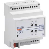
| Product Type | Universal Dimmer Actuator Easy 500 VA |
| Brand | Gewiss |
| Model | GW90849 |
| Category | Smart Home |
| Bus Power Supply | 29 V DC SELV via KNX bus |
| Rated Load Voltage | 230 V AC, 50 Hz |
| Total Permissible Power | 40-500 W (incandescent lamps), 40-500 VA (inductive loads), 40-500 VA (capacitive loads) |
| Dimensions | 4 DIN modules |
| Operating Temperature | -5 to +45 °C |
| Storage Temperature | -25 to +55 °C |
| Relative Humidity | Max 93% (non-condensing) |
| Protection Degree | IP20 |
| Communication | KNX TP1 bus |
| Current Consumption on Bus | 9 mA max |
| Main Functions | On/Off, brightness adjustment (13%-100%), timed commands, priority commands, 8 scene management |
| Control Elements | 1 miniature programming button, 1 manual ON/OFF pushbutton |
| Visual Indicators | 1 red programming LED, 1 status LED (green=ON, red=overload, yellow flashing=no mains voltage) |
| Bus Connection | 2-pin terminals ∅ 1 mm |
| Electrical Connections | Screw terminals, max cable cross-section: 2.5 mm² |
| Protection | High interruption capacity fuse max 2.5 A |
| Maintenance and Cleaning | Use a dry cloth |
| Safety | Installation by qualified personnel only; comply with IEC 60364, EN50428, EN50090-2-2; disconnect mains before connection |
| Reference Standards | Low Voltage Directive 2006/95/EC, EMC Directive 2004/108/EC |
| Certifications | KNX/EIB |
Frequently Asked Questions - GW90849 Gewiss
User questions about GW90849 Gewiss
0 question about this device. Answer the ones you know or ask your own.
Ask a new question about this device
Download the instructions for your Smart Home in PDF format for free! Find your manual GW90849 - Gewiss and take your electronic device back in hand. On this page are published all the documents necessary for the use of your device. GW90849 by Gewiss.
USER MANUAL GW90849 Gewiss
Local command push-button
Bouton-poussoir de commande locale
Button key for programming
Terminals for connecting loads
2.5A fuse with high breaking capacity
PROGRAMMING WITH THE EASY CONFIGURATOR.... 19
IN SERVICE 21
TECHNICAL DATA 22
GENERAL WARNINGS
Warning! The safety of this appliance is only guaranteed if all the instructions given here are followed scrupulously. These should be read thoroughly and kept in a safe place. Chorus products can be installed in environments which are dust-free and where no special protection against the penetration of water is required.
They shall be installed in compliance with the requirements for household devices set out by the national standards and rules applicable to low-voltage electrical installations which are in force in the country where the products are installed, or, when there are none, following the international standard for low-voltage electrical installations IEC 60364, or the European harmonization document HD 60364.
Gewiss sales organization is ready to provide full explanations and technical data on request.
Pack contents
1 Easy universal dimmer actuator 500 VA - DIN rail mounting
1 BUS terminal
1 Cover with screw
1 User and Installation Manual
Briefly
The universal dimmer actuator 500VA – DIN rail mounting allows you to command and adjust incandescent lamps, inductive loads (low voltage halogen lamps, via winding transformers) and capacitive loads (low voltage halogen lamps, via electronic transformers).
The dimmer actuator is powered from the BUS line, and has a front LED to indicate the output status (LED not lit up when OFF, green when ON, red if the output is overloaded). The dimmer actuator is used to switch the connected load on and off, adjust the degree of light intensity, perform timed commands, perform priority commands for forcing the output status, memorise and execute scenes. The various operating modes can be used simultaneously.
The dimmer actuator is assembled on a DIN rail, inside electric boards or junction boxes.
Functions
The actuator can be configured with the Easy controller to carry out the following functions:
ACTIVATION AND DEACTIVATION OF LOADS
The dimmer actuator activates (100%) or deactivates (0%) the electric load when it receives the ON/OFF commands sent - for example - from a contacts interface or a push-button panel configured in Cyclic ON/OFF switchover mode or Fronts management mode. The status LED lights up to show the output is active.
BRIGHTNESS ADJUSTMENT
Used to switch the light on and off, or to vary its intensity (increasing from 13% to 100%, or decreasing from 100% to 13%), depending on the commands received from the other KNX devices. The status LED lights up to show the output is active.
The device can accept percentage light intensity commands on its input.
GENERAL DESCRIPTION
EXECUTION OF TIMED COMMANDS
The dimmer actuator activates the connected electric load at full power for the time specified in the Activation time parameter, subsequently deactivating it when this period has elapsed. For instance, this is the setting for the stair raiser light. If the dimmer actuator receives a new ON command with timing during the activation period, the time count starts again from the beginning. If an OFF command is sent before the time has elapsed, the light will be switched off. The status LED lights up to show the output is active. With the Pre-warning time parameter, you can enable the switch-off pre-warning: in this case, the device decreases the light intensity value for the set time leading up to switch-off. You can therefore send a new timed command before the light switches off completely.
EXECUTION OF PRIORITY COMMANDS
The dimmer actuator activates (100%) or deactivates (0%) the commanded load on the basis of the command (ON or OFF) transmitted by the device that sends the priority command. Until it receives a command to annul the forcing, the dimmer ignores all the other commands received (including commands from the front push-button). If no other commands are received, at the end of the forcing the actuator will return to the status it had before the forcing activation. Otherwise, it will adopt the status of the last command received (a light intensity increase/decrease command will be ignored). The status LED lights up to show the output is active.
SCENE MANAGEMENT
The dimmer actuator can memorise and manage up to 8 scenes. The light intensity values can be memorised and called up via Easy devices or conventional push-buttons connected to the BUS via a contacts interface. You can create a maximum of 8 scenes, with varying light intensity values. When it receives the command, the dimmer brings the load to the value previously set. The status LED lights up to show the output is active.
STATUS INDICATOR LED
| Status of the LED for output status signalling | |
| OFF | Load not piloted (OFF or adjustment value 0%), and mains voltage present |
| Green | Load piloted (ON or adjustment value different from 0%), and mains voltage present |
| Red Output overload | |
| Flashing yellow Mains voltage absent, and BUS voltage present | |
| Flashing red Reset after overload (5 sec) | |
INSTALLATION

ATTENTION: the device must only be installed by qualified personnel, observing current regulations and the guidelines for KNX installations.
Recommendations for installing the KNX
- The length of the BUS line between the dimmer actuator and the power supply unit must not exceed 350 metres.
- The length of the BUS line between the dimmer actuator and the furthest KNX device must not exceed 700 metres.
- To avoid unwanted signals and overvoltages, do not use ring circuits.
- Keep a distance of at least 4mm between the individually insulated cables of the BUS line and those of the electricity line (figure C).
- Do not damage the electrical continuity conductor of the shielding (figure D).
ATTENTION: The unused bus signal cables, and the electrical continuity conductor, must never touch any live elements or the earthing conductor!
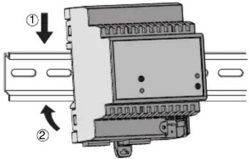
Assembly on the DIN rail
Assemble the dimmer on a 35mm DIN rail in the following way (figure E):
- Insert the upper device coupling in the DIN rail.
- Rotate the device, then lock it in place on the DIN rail by means of the fixing tab.
Electric connections

ATTENTION: disconnect the mains voltage before connecting the device to the electricity supply!
Figure B shows a diagram of the electrical connections.
- Connect the red wire of the BUS cable to the red clamp (+) of the terminal, and the black wire to the black clamp (-). Up to 4 BUS lines can be connected to the BUS terminal (same coloured wires on the same terminal) (figure F).
- Insulate the shield, the electrical continuity conductor, and the other white and yellow wires of the BUS cable (if a 4-conductor BUS cable is being used), that are not necessary (figure D).
- Insert the BUS clamp in the pins of the device. The correct connection direction is determined by the fixing guides. Insulate the BUS terminal with the special cover, that must be screwed onto the device. The cover guarantees the minimum separation distance of 4mm between the power cables and the BUS cables (figure G).
- Connect the load to the relevant screw terminals, making sure the current limits specified in the Technical Data are not exceeded.
- Protect the dimmer by inserting a fuse with high breaking capacity (max. 2.5A) on the power supply line.
Initialisation with Easy Controller
- Power the device via the BUS.
- Follow one of these procedures for the system to acquire the device:
• Automatic acquisition:
- select the "Find/Configure" or "Scan" command on the "System" menu
- Manual acquisition:
- select the "Add device" menu from the "System" menu
- press the programming button key briefly (< 2 seconds). The programming LED turns on during the acquisition process (figure A).
The acquired device is listed with an assigned number, product code and list of channels, on the “Devices” screen.
Initialisation with the Easy base unit (GW 90 831)
- Power the device via the BUS.
- Follow one of these procedures for the system to acquire the device:
- Automatic acquisition (the device still has the factory settings):
- in the Easy base unit, select the “Application → New function” or “Application → Edit function” menu: the device will be recognised automatically
- Manual acquisition (factory default settings have been changed):
- in the Easy base unit, select the "Application → Find device" menu
- press the programming button key briefly (< 2 seconds). The programming LED turns on during the acquisition process (figure A).
The device acquired by the Easy base unit will be listed (with the number assigned to it) in the channels of the “Application → New function” or “Application → Edit function” menu.
PROGRAMMING WITH THE EASY CONFIGURATOR
Program the actuator using the Easy controller (GW 90 837 / GW 90 838 / GW 90 840) or an Easy base unit (GW 90 831).
The channel of the dimmer actuator (to be used in the function you want to create) can be selected:
- by pressing the local command push-button: the corresponding channel will then be highlighted on the list of channels
• or directly, from the list of channels
The functions can be created once the devices have been selected.
| Name of the functions | |
| dimming toggle | brightness adjustment with 1 push-button |
| dimming | brightness adjustment with 2 push-buttons |
| toggle | load activation or deactivation |
| edges | load activation or deactivation |
| light intensity value | sending of light intensity values |
| priority control | sending of priority commands |
| timer mode | ON command with timing |
| scene | scene activation |
For more details about the programming procedures please refer to the Easy base unit or Easy controller documentation.
Configuration parameters (Easy)
Once the required function has been created, the operating parameters of the actuator can be set. The parameters available, in relation to the function created, are listed in the tables below. The value underlined is the default value.
| Function: timer mode | |
| Parameter: switch-on time | |
| not active no timing | |
| 1 second output activated for 1 second | |
| 2 seconds output activated for 2 seconds | |
| 3 seconds output activated for 3 seconds | |
| 5 seconds output activated for 5 seconds | |
| 10 seconds output activated for 10 seconds | |
| 15 seconds output activated for 15 seconds | |
| 20 seconds output activated for 20 seconds | |
| 30 seconds output activated for 30 seconds | |
| 45 seconds output activated for 45 seconds | |
| 1 minute output activated for 1 minute | |
| 1 minute 15 secs output activated for 1 minute 15 seconds | |
| 1 minute 30 secs output activated for 1 minute 30 seconds | |
| 2 minutes output activated for 2 minutes | |
| 2 minutes 30 secs output activated for 2 minutes 30 seconds | |
| 3 minutes output activated for 3 minutes | |
| 5 minutes output activated for 5 minutes | |
| 15 minutes output activated for 15 minutes | |
| 20 minutes output activated for 20 minutes | |
| 30 minutes output activated for 30 minutes | |
| 1 hour output activated for 1 hour | |
| 2 hours output activated for 2 hours | |
| 3 hours output activated for 3 hours | |
| 5 hours output activated for 5 hours | |
| 12 hours output activated for 12 hours | |
| 24 hours output activated for 24 hours | |
Configuration parameters (Easy)
| Function: timer mode | |
| Parameter: pre-warning time | |
| no pre-warning | no pre-warning |
| 15 seconds | pre-warning 15 seconds before load switch-off |
| 30 seconds | pre-warning 30 seconds before load switch-off |
| 1 minute | pre-warning 1 minute before load switch-off |
Using the local command push-button
The manual command push-button (figure A) allows the cyclical ON/OFF switchover, bringing the light intensity level from 0% to 100% and vice versa every time it is pressed. If a priority command is active, the local commands are not executed.
▶Behaviour upon the failure and resetting of the BUS power supply
When the BUS power supply fails, the device brings the output to the OFF position (0%). When the BUS power supply is reset, the output resumes the light intensity value in force before the power failure.
Overload management
Any possible overload is signalled by a fixed red light on the front LED. During the overload situation, the dimmer output is switched off and every command received from the BUS is ignored. Once the cause of the overload has been eliminated, you can restore normal operation and deactivate the overload signal in the following ways:
- via the front command push-button of the dimmer, and commanding the output. The dimmer will assume the maximum light intensity value and, after about 5 seconds (if the overload has been eliminated), the status LED will switch on with a fixed green light. The front button key allows the dimmer to be commanded even in the event of an overload. During the reset operation (about 5 seconds), the front LED turns red and flashes;
- by disconnecting the 230V AC mains voltage (with the BUS voltage present). When the mains voltage is restored, you can send a command via the BUS or command the dimmer via the front push-button. Regardless of the command received, the dimmer will bring the load to the maximum light intensity value. After about 5 seconds (if the overload has been eliminated), the status LED will switch on with a fixed green light and the dimmer will execute the last command received. During the reset operation (about 5 seconds), the front LED turns red and flashes.
Maintenance
Use a dry cloth if cleaning is required.
TECHNICAL DATA
| Communication | KNX BUS |
| Power supply | via KNX BUS, 29V DC SELV |
| BUS cable | KNX TP1 |
| Bus current consumption | 9 mA max |
| Command elements | 1 miniature programming button key |
| 1 manual ON/OFF command push-button | |
| Display elements | 1 red programming LED |
| 1 LED for output status signalling | |
| Rated voltage | 230V AC, 50Hz |
| Total allowed power | Incandescent lamps: 40-500W |
| Halogen lamps: 40-500W | |
| Inductive loads: 40-500VA | |
| Capacitive loads: 40-500VA | |
| Maximum dissipated power | 10W |
| Ambit of use | Indoors, dry places |
| Operating temperature | -5 ÷ +45°C |
| Storage temperature | -25 ÷ +55°C |
| Relative humidity | Max 93% (non condensative) |
| BUS connection | 2-pin coupling terminal - ∅ 1mm |
| Electrical connections | Screw terminals - max. cable section: 2.5mm2 |
| Protection ratings | IP20 |
| Dimension | 4 DIN modules |
| Reference standard | Low Voltage Directive 2006/95/EC |
| Electromagnetic Compatibility Directive 2004/108/EC | |
| EN50428, EN50090-2-2 | |
| Certifications | KNX/EIB |
page
CONSIGNES GÉNÉRALES 24
DESCRIPTION GÉNÉRALE 25
INSTALLATION 27
PROGRAMMATION À L'AIDE DU CONFIGURATEUR EASY 29
EN SERVICE 31
CARACTÉRISTIQUES TECHNIQUES 32
CONSIGNES GÉNÉRALES
Gestion de la surcharge
① Cavo bus - Bus cable - Câble bus - Cable bus - Buskabel
② Conduttore di continuità elettrica - Electrical continuity conductor - Conducteur de continuité électrique - Conductor de continuidad eléctrica - Stromdurchgangsleiter
③ Schermatura - Shielding - Blindage - Blindaje - Abschirmung
E
F
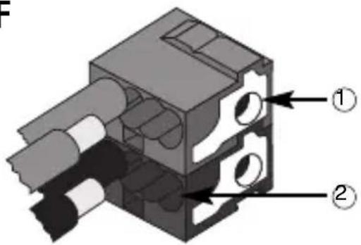
① Connessione dispositivo bus
Bus device connection - Connexion dispositif bus - Conexión dispositivo bus Anschluss Busvorrichtung
natural_image
Diagram of a mechanical assembly with numbered components and a downward arrow indicating a process (no text or symbols present)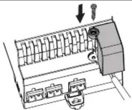
natural_image
Diagram of a mechanical device with multiple ports and a valve, showing no text or symbolsAccording to article 9 paragraph 2 of the European Directive 2004/108/EC and to article R2 paragraph 6 of the Decision 768/2008/EC, the responsible for placing the apparatus on the Community market is:
GEWISS S.p.A Via A. Volta, 1 - 24069 Cenate Sotto (BG) Italy Tel: +39 035 946 111 Fax: +39 035 945 270 E-mail: qualitymarks@gewiss.com


+39 035 946 111
8.30-12.30/14.00-18.00

- GENERAL WARNINGS
- Pack contents
- Briefly
- Functions
- ACTIVATION AND DEACTIVATION OF LOADS
- BRIGHTNESS ADJUSTMENT
- GENERAL DESCRIPTION
- EXECUTION OF TIMED COMMANDS
- EXECUTION OF PRIORITY COMMANDS
- SCENE MANAGEMENT
- INSTALLATION
- Recommendations for installing the KNX
- Assembly on the DIN rail
- Electric connections
- Initialisation with Easy Controller
- Initialisation with the Easy base unit (GW 90 831)
- PROGRAMMING WITH THE EASY CONFIGURATOR
- Configuration parameters (Easy)
- Using the local command push-button
- ▶Behaviour upon the failure and resetting of the BUS power supply
- Overload management
- Maintenance
- TECHNICAL DATA
- CONSIGNES GÉNÉRALES
- Gestion de la surcharge
Brand : Gewiss
Model : GW90849
Category : Smart Home