S4 Explorer - Scrubber Ghibli - Free user manual and instructions
Find the device manual for free S4 Explorer Ghibli in PDF.
Frequently Asked Questions - S4 Explorer Ghibli
Questions des utilisateurs sur S4 Explorer Ghibli
0 question sur cet appareil. Repondez a celles que vous connaissez ou posez la votre.
Poser une nouvelle question sur cet appareil
Download the instructions for your Scrubber in PDF format for free! Find your manual S4 Explorer - Ghibli and take your electronic device back in hand. On this page are published all the documents necessary for the use of your device. S4 Explorer by Ghibli.
USER MANUAL S4 Explorer Ghibli
The machine's identification data and "CE" marking can be found on the plate which is positioned beneath the control console.
It is advisable to make a note of the machine model and the relative serial number shown on the following page.

DONNÉES D'IDENTIFICATION
(Translation of original instructions)
FR
Francais FR-1
PROBLEMI - CAUSE - RIMEDII I-32
SCHEMA ELETTRICO I-34
Dati tecnici
Rumorosita .66 dB (A)
Serbatoio
Thank you for choosing one of our cleaning products.
The floor scrubber dryer that you have purchased has been designed to satisfy the user in terms of ease of use and reliability over time.
We are aware that in order for a good product to stay that way, over time, it requires continuous updates aimed at meeting the expectations of those who use it on a daily basis. For this reason, we hope that you will not only be a satisfied customer but also a partner who does not hesitate to give us your opinions and ideas originating from your personal day-to-day experience.
Contents
Technical data. EN-3
1.1 INTRODUCTION EN-4
1.1.a - Purpose of the manual EN-4
1.1.b - Consulting the manual EN-4
1.1.c - Key to symbols used in the manual EN-4
1.1.d - Conventional terminology EN-4
1.2 GENERAL WARNINGS EN-4
1.2.a - Personnel qualifications EN-4
1.2.b - Operator position EN-5
1.2.c - Protective clothing.. EN-5
1.2.d - General warnings before use EN-5
1.2.e - General warnings while using the machine EN-5
1.2.f - General warnings about the batteries .EN-5
1.2.g - General warnings during maintenance EN-5
1.2.h - General warnings in the event of a fire EN-6
1.2.i - Prolonged machine standstill EN-6
1.3 INTENDED MACHINE USE EN-6
1.4 NON-INTENDED MACHINE USE EN-6
1.4.a - Zone with risk of explosion EN-6
1.5 DEMOLISHING THE MACHINE EN-6
1.6 REFERENCE STANDARDS EN-6
2.1 UNPACKING EN-7
2.1.a - Standard machine equipment EN-7
2.1.b - Battery installation.. EN-8
2.1.c - Unloading the machine from the wooden pallet. EN-10
3.1 ASSEMBLY COMPONENTS EN-11
3.1.a - Squeegee installation EN-11
4.1 CHARGING THE BATTERY EN-11
4.1.a - Charging the batteries with the on-board battery charger (if present) ....EN-12
4.1.b - Charging the battery with an external battery charger EN-13
5.1 GETTING TO KNOW THE MACHINE EN-15
5.2 MACHINE CONTROLS EN-15
6.1 DESCRIPTION OF THE CONTROLS EN-16
6.1.a - Left-side handlebar controls EN-16
6.1.b - Right-side handlebar controls EN-16
6.1.c - Emergency button EN-17
6.1.d - Control panel.. EN-17
7.1 SAFETY DEVICES EN-20
8.1 FILLING THE TANK EN-21
9.1 OPERATION EN-21
9.1.a - Checks before use EN-21
9.1.b - Preparing the machine and choosing the cycle EN-22
9.1.c - Using the machine EN-22
9.1.d - Alarms during function. EN-23
9.1.e - End of use and shutdown EN-24
10.1 DRAINING THE RECOVERY WATER EN-24
11.1 MAINTENANCE AND CLEANING EN-25
11.1.a - Emptying and cleaning the clean water tank .EN-25
11.1.b - Cleaning the recovery water tank .EN-26
11.1.c - Cleaning the wiper EN-27
11.1.d - Cleaning the clean water filter EN-27
11.1.e - Check the wear status of the steering chain EN-28
11.1.f - Replacing the brushes . EN-28
11.1.g - Replacing the squeegee rubber blades EN-29
11.1.h - Adjusting the pressure of the squeezegee EN-29
11.1.i - Checking the wear status of the three wheels EN-30
11.1.1 - Battery charger configuration EN-31
TROUBLESHOOTING EN-32
WIRING DIAGRAM EN-34
Technical data
Type of use. Operator on board
Characteristics
Operation . Batteries
Type of batteries. N^4 - 6V - 180Ah (C5)
Power supply Battery 24V
Installed load 1800 W
Forward movement.Forward/reverse movement
Washing width 700 mm
Drying width 900 mm
Theoretical hourly working capacity 4200 m²/h
Clean water tank capacity . 80 litres
Recovery water tank capacity. 90 litres
Hand-arm system vibration. 1,3 m/s2
Full body vibration 0,55 m/s2
Sound pressure 68 db(A)
Brushes
Diameter / pad / number 360 mm / 14" x 2
Motor power / number 250 W x 2
Motor speed 165 rpm
Specific pressure 42 gr / cm²
Traction
Maximum gradient which can be overcome at full load 12 %
Motor power / number 350 W x 2
Maximum forward speed while in function. 6 km/h
Maximum forward speed while not in function. 8 km/h
Aspiration
Motor power. 550 W
Negative pressure (water column). 165 / 1700 mbar / mmHO
Air flow rate. 321/sec
Noise level. 66 dB (A)
Tank
Type. Dual tank
Recirculation . No
Solution capacity 801
Recovery capacity 901
Dimensions 1570 x 760x 1080 mm
Weight
Empty weight 204 kg
Weight with batteries 328 kg
Vehicle curb weight 483 kg
1.1 - INTRODUCTION
The manual is an integral part of the machine itself; it must therefore be stored carefully in a safe place which is accessible to all users (operators and personnel in charge of maintenance) for the entire machine life until demolition.
1.1.a - Purpose of the manual
The purpose of the manual is to provide the instructions necessary for putting into service, using and maintaining the machine with which it is enclosed.
It is advisable to read the instructions carefully and comply with the safety standards described in the manual to the letter.
The non-observation of these instructions/ standards may cause damage to the machine and injury to the operator for which under no circumstances is the manufacturer responsible.
The safety information described in the manual supplements and DOES NOT REPLACE standards in force in the country in which the machine is used.
1.1.b - Consulting the manual
The manual is divided into chapters according to a logical order of knowledge and use of the machine.
For help with finding a specific topic, first consult the CONTENTS shown at the beginning of the manual.
1.1.c - Key to symbols used in the manual
In order to highlight information and procedures regarding safety, maintenance etc., the following symbols have been adopted in the manual:

DANGER:
Warns of a serious, even fatal danger for the safety of the operator and/or third persons.

WARNING:
Extremely important information in order to prevent serious damage to the machine and the environment in which it operates.

NOTE:
Additional information for correct machine operation or of a general nature.
1.1.d - Conventional terminology
The frontal, rear, forward, reverse, upper, lower, left and right indications refer to the operator sitting in the driver's seat with
his/her hands on the handlebars.
To simplify, the brand name of the model has been replaced with "Machine".
1.2 - GENERAL WARNINGS
Before putting into service, using and maintaining the machine, it is necessary for the persons involved (persons in charge and operators) to be trained regarding the operating procedures and safety standards shown in this manual.
Respect all the provisions contained in the manual and in any enclosed documentation.

DANGER:
It is forbidden for untrained personnel, children and disabled persons to use the machine.
1.2.a - Personnel qualifications
Operator
The term operator refers to a generic worker able to perform simple operations such as running the machine and carrying out the relative cleaning at the end of the working shift.
Electrical/mechanical maintenance technician
A technician qualified to operate on the machine in order to repair or replace parts which require the removal of the protective cover.
1.2.b - Operator position
When using the machine, the operator is seated in the operator's seat with his/her hands on the handlebars.
1.2.c - Protective clothing
- Use protective clothing as indicated in the standards in force in the country in which the machine is used.
1.2.d - General warnings before use
- Before using the machine, check that the fixed safety guards (covers) are always correctly secured in position.
1.2.e - General warnings while using the machine
- If the machine makes strange noises, stop it immediately and identify the cause.
- DO NOT leave the machine unattended on inclined surfaces of grades above 12% .
- The machine has a gradeability load of 12% .
- It is absolutely forbidden to turn while on ramps; danger of tipping/overturning.
- While using the machine, do not knock into shelving or cupboards.
- Avoid using the machine in environments where there is a risk of falling objects.
- It is forbidden to use the machine outdoors or on public roads.
- If possible, use the machine in environments where no persons are present; in the present of unauthorised persons, warn them to move away before using the machine.
- Do not use the machine in environments with the presence of corrosive or salty substances.
- Do not use the machine in explosive environments (ATEX).
1.2.f - General warnings about the batteries
- The battery's acid is corrosive: in the event of skin contact, rinse abundantly with water.
- Use appropriate personal protection equipment to avoid contact with the skin (see standards in force in the country in which the machine is used).
- Do not inhale the vapour: it is dangerous.
- As mixtures of explosive gasses may form during battery charging, the battery charging environment must be well-ventilated and must comply with the current relative standards.
- It is forbidden to smoke and/or use naked flames within 2 metres of the battery during charging, in the charging area and while the battery is cooling after charging.
- Report any liquid leaking from the battery: leaks are dangerous and highly polluting.
1.2.g - General warnings during maintenance
- Disconnect the batteries/electric cable before performing maintenance and repair operations.
- Do not rest tools and metal objects on the batteries; danger of short circuits.
- Do not use aggressive detergents, acid, lye etc. during cleaning and washing and take particular care with electrical parts.
- Do not wash the machine with direct or pressurised jets of water.
- When the machine must be lifted for any maintenance operations, it is necessary to work safely by placing fixed supports underneath it.
- Contact an authorised support centre for repairs and request ORIGINAL spare parts only.
1.2.h - General warnings in the event of a fire
- In the event of a fire, use approved powder extinguishers only; do NOT use water to put out the fire.
1.2.i - Prolonged machine standstill
- Place the machine under cover, sheltered from atmospheric agents in a place where the temperature is between 5^ and +40^ .
- Remove the ignition key.
- Drain the clean water contained in the tank.
- Charge the batteries and, once they are charged, disconnect them from the charger.
- Charge the batteries once a month.
1.3 - INTENDED MACHINE USE
The machine has been designed and manufactured for washing and drying indoor floor surfaces.

DANGER:
Any other use releases the manufacturer from responsibility for damage or injury to persons and/or things and invalidates any warranty condition.
1.4 - NON-INTENDED MACHINE USE

WARNING:
The machine is not intended for outdoor use.

DANGER:
- Do not wash floors with water of temperatures in excess of 50^ ;
- Do not wash floors with these line or corrosive detergents;
-
Do not use corrosive, flammable explosive liquids for washing or vacuuming operations, even if diluted;
-
Do not operate the machine with the recovery tank open;
- Hands and feet must be kept on board while the machine is in motion;
- Do not make sudden turns, especially during downhill movements.

WARNING:
Only ONE PERSON at a time is to be permitted on board the machine.
1.4.a - Zone with risk of explosion
It is strictly forbidden to use the machine in environments where there is a risk of explosion with the presence of flammable and explosive gases, vapours, liquids and powders.
1.5 - DEMOLISHING THE MACHINE
In order to protect the environment, make sure that the machine is disposed of in accordance with the current local regulations. When the appliance can no longer be used or repaired, proceed with the separate disposal of its components.

DANGER:
The machine's batteries are to be considered as special waste and must therefore be disposed of at appropriate collection facilities, as prescribed by the current regulations in the country of use.
In consideration of the substances and materials contained, inadequate or abusive disposal of the equipment or its improper use may cause damage or injury to persons and the environment.
1.6 - REFERENCE STANDARDS
This machine has been designed and built in compliance with the current machinery directive and in compliance with the standards indicated in the "CE" declaration of conformity furnished with the machine.
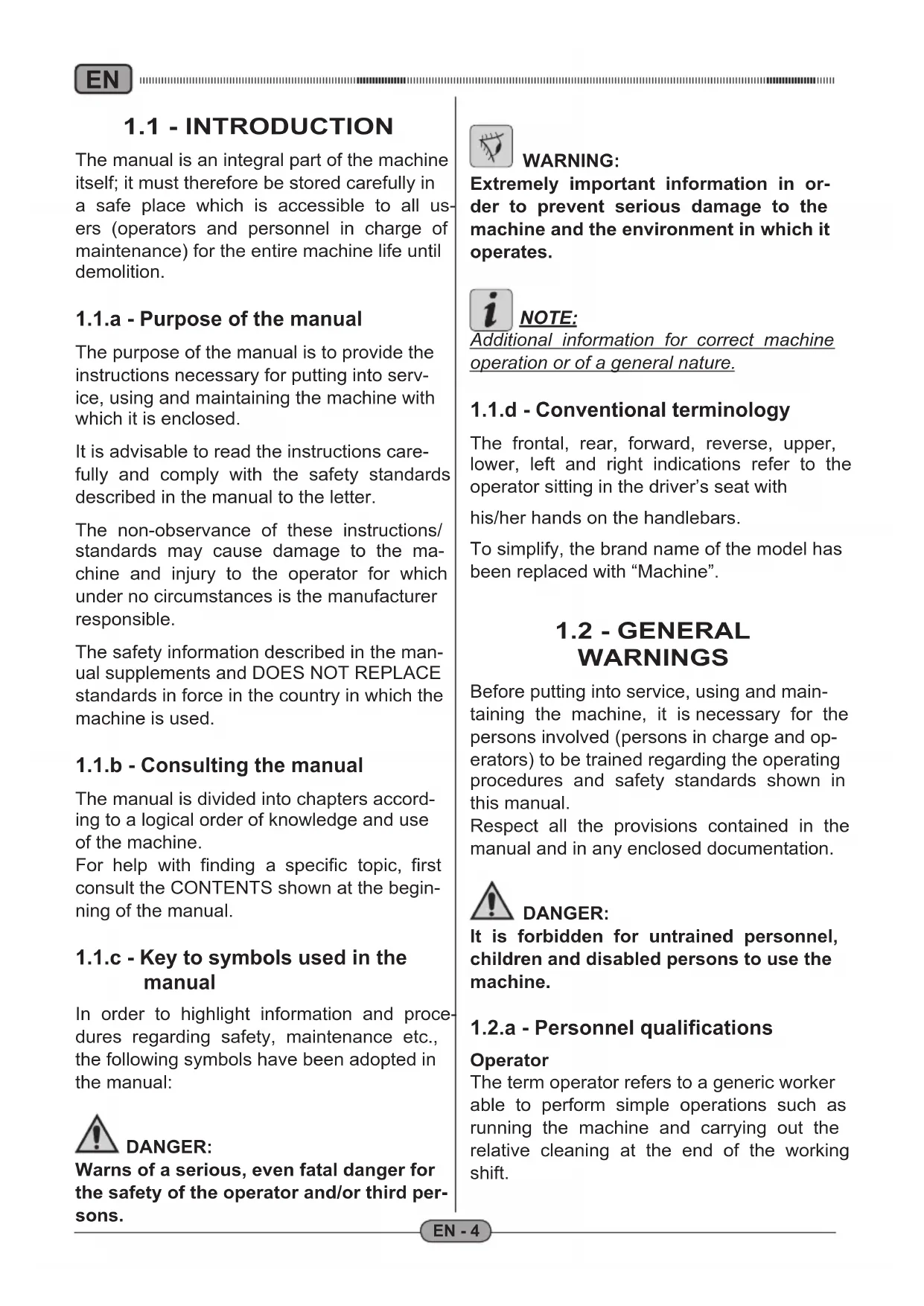
2.1 - UNPACKING (Fig. 1)
Once the packaging has been removed as shown in the instructions on the packaging itself, check that the machine and all the components supplied are intact.
If any evident damage is found, contact the area agent and the carrier within 3 days of receipt.
- Remove the pack (1) containing the accessories supplied.
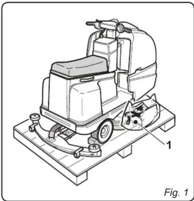
2.1.a - Standard machine equipment (Fig. 2)
The accessories supplied are as follows:
1) Flexible water intake tube (found at the tank's intake opening).
2) Machine use and maintenance manual.
3) Battery charger instruction manual (if present).
4) Battery charger power supply cable (if on-board battery charger is present).
5) 2 brushes (machine mounted).

EN
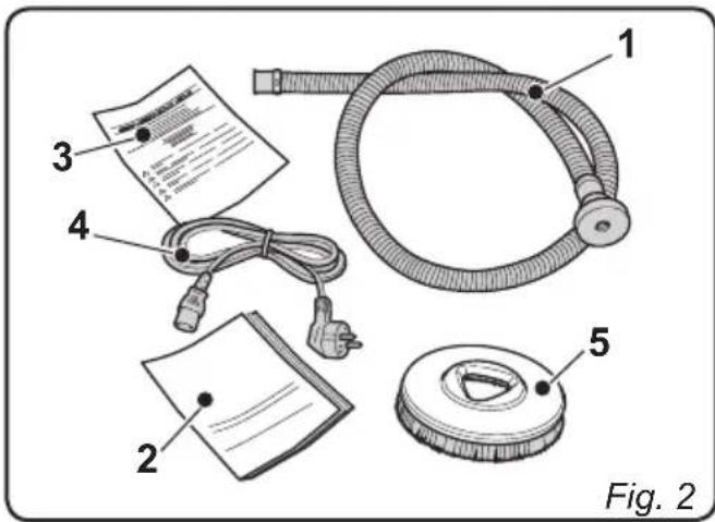
2.1.b - Battery installation (Fig. 3/4)
- Lift the seat (1).
- Loosen the knobs (2) which fasten the protective guard (3).
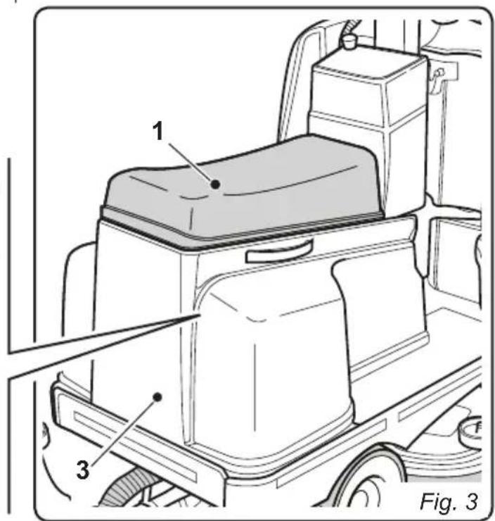
- Disconnect the wires (4) of the operator-presence sensor (5).
- Remove the protective guard (3), lifting it using the appropriate handles (6), and disconnect the emergency button's socket (A).
-
Position the batteries as shown in the diagram and connect them as shown in the electrical scheme below using the supplied cables and plugs.
-
Connect the plug for the batteries (7) to the socket (8).
- Reposition the protective guard (3) and reconnect the wires of the operator-presence sensor, performing their disassembly operations in reverse order.

NOTE:
The batteries must be installed and connected by qualified personnel.
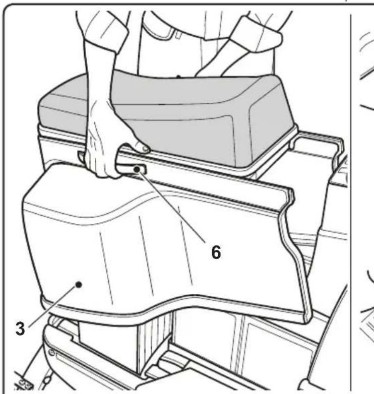
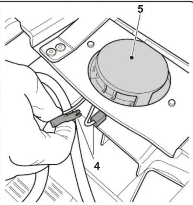
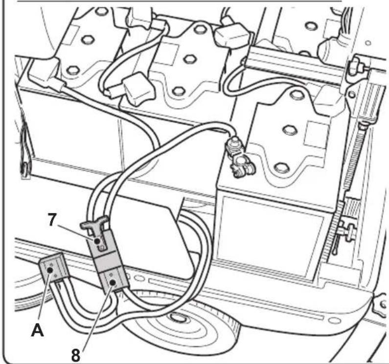
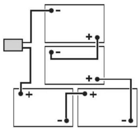
Fig. 4
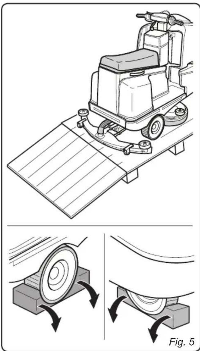
2.1.c - Unloading the machine from the wooden pallet (Fig. 5-6)
- Position a ramp (1) and fasten it to the wooden pallet.
- Remove the wooden blocks (2) from the three wheels.
- Check that the emergency arrest button (3) is not engaged.

NOTE:
In order to disengage the emergency arrest button, turn it in the direction indicated by the arrow on its head.
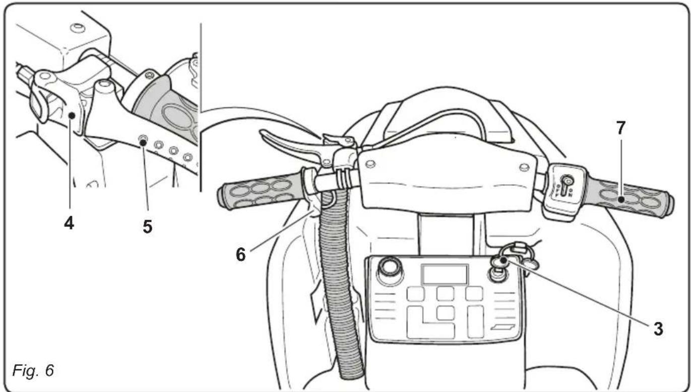
- Sit in the operator's seat and start the machine by turning the key (3) to its ON position.
- Wait for the brush support unit to be raised.
- Release the parking brake by disengaging the lever's (5) locking device (4).
- Press the frontal part of the button (6) towards the rear of the machine, thereby selecting movement in reverse; “↓” will appear on the display.
- Activate the accelerator handle (7) and drive down the ramp off of the pallet.
3.1 - ASSEMBLY COMPONENTS
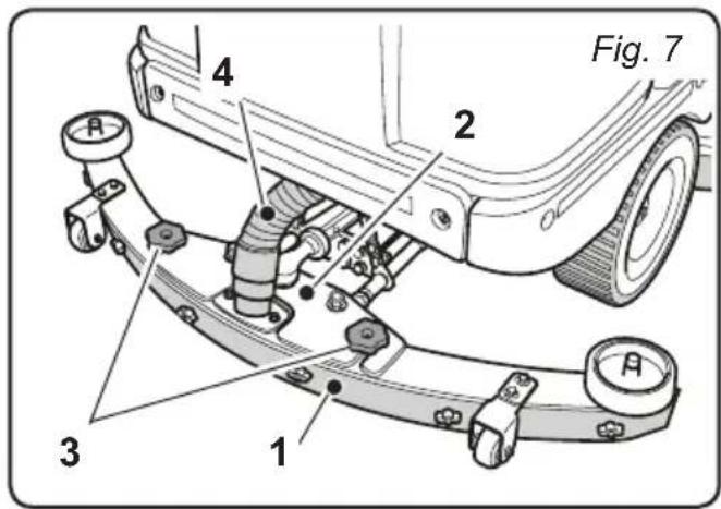
3.1.a - Squeegee installation (Fig.7)
- Insert the squeezegee (1) into its support plate (2) and fasten it by tightening the two knobs (3).
- Connect the suction tube (4) to the squeezegee's intake opening.
4.1 - CHARGING THE BATTERY

DANGER:
Charge the batteries in well-ventilated areas which comply with standards in force in the country of use.
For safety-related information, follow what is described in chapter 1 of this manual.

WARNING:
For the information and warnings relative to the battery and the on-board battery charger (if present), refer to that which is indicated in the battery charger's manual, attached to this user and maintenance manual.

WARNING:
The machine comes pre-calibrated for function with gel batteries. If acid batteries are to be installed, please contact our Assistance Centre in order to re-calibrate the machine.
It is forbidden to use the machine with gel batteries if it has been calibrated for use with acid batteries.

NOTE:
For more information regarding machine calibration, see section 11.1.l.

NOTE:
10 hours are needed for complete battery charging. Avoid partial recharges.
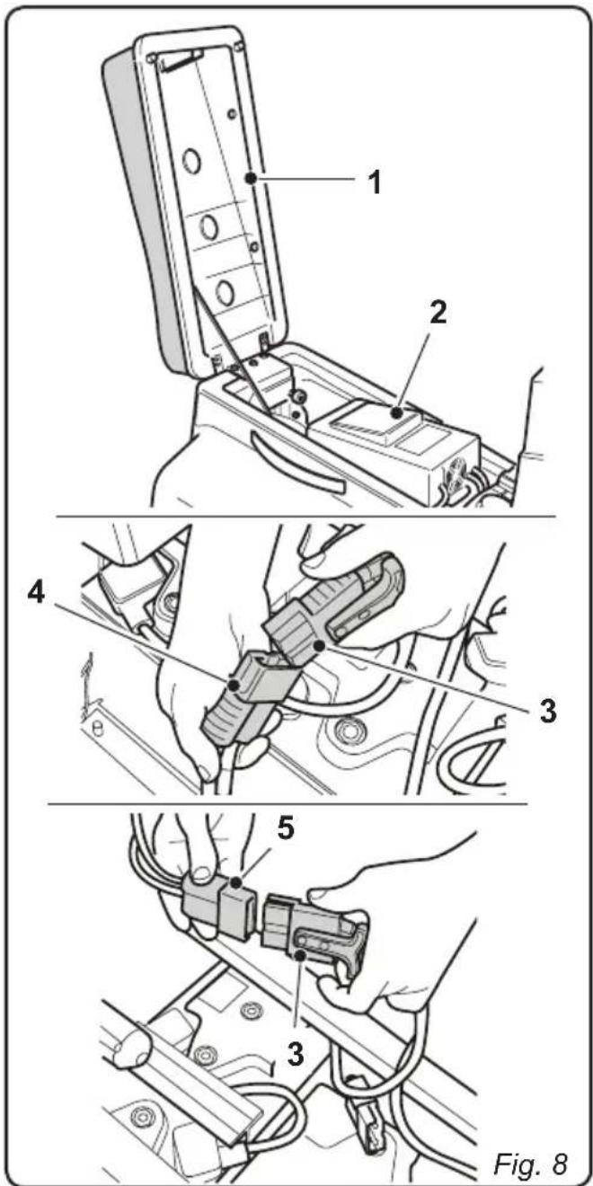
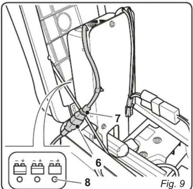
4.1.a - Charging the batteries with the on-board battery charger (if present) (Fig. 8-9)
- Move the machine to the vicinity of a main electrical socket.
- Lift the seat (1) and the battery charger (2).
- Disconnect the battery plug (3) from the socket (4) of the machine's electrical system.
- Connect the battery plug (3) to the onboard battery charger's outlet (5).
- Remove the cable from the kit (6) and connect it to the socket (7) on the machine then connect the other end to the mains socket.

WARNING:
Make sure that the system voltage is compatible with the battery charger's input voltage (100-130 Vac or 200-230 Vac, 50 / 60Hz ).
- Leave the batteries to charge until the "Green" LED (8) comes on, then remove the power cable (6) and put it back in position.
- Reconnect the battery plug (3) to the socket of the machine's electrical system (4) then lower the battery charger (2) and seat (1) again.
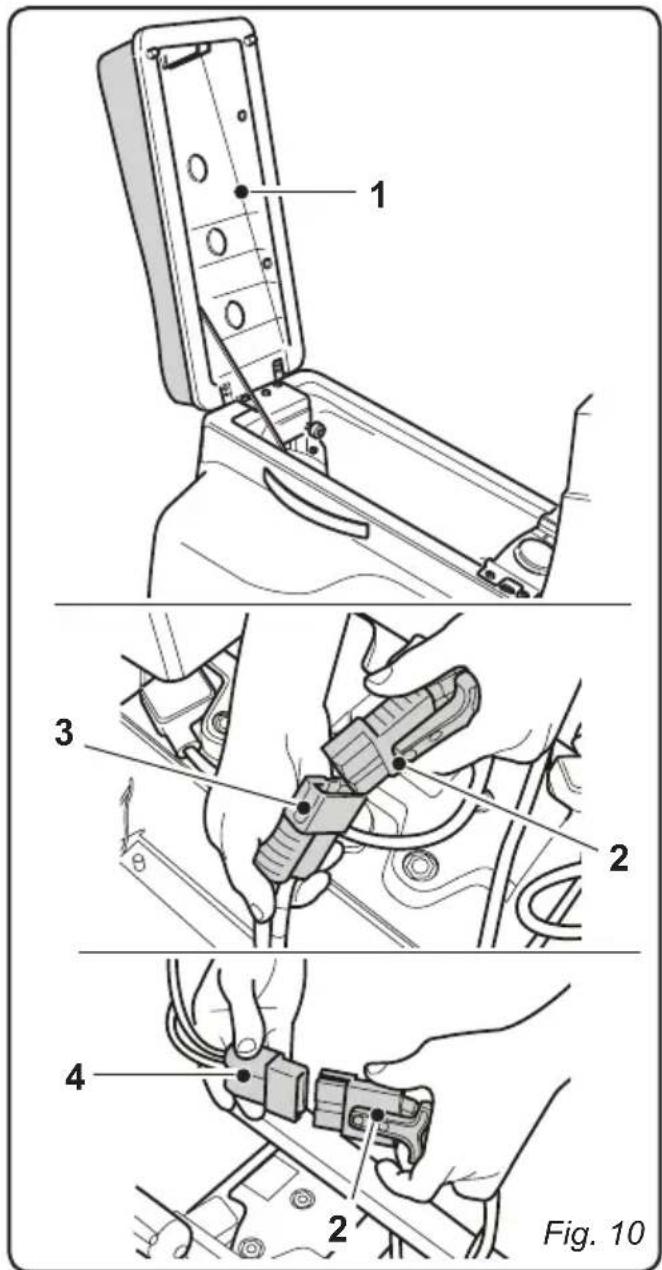
4.1.b - Charging the battery with an external battery charger (Fig. 10)
- Move the machine near the battery charging station.
- Lift the seat (1).
- Remove the battery plug (2) from the socket (3) of the machine's electrical system.
- Connect the battery plug (2) to the external battery charger's outlet (4).
- Once the batteries have been charged, reconnect the battery plug (2) to the socket (3) of the machine's electrical system.
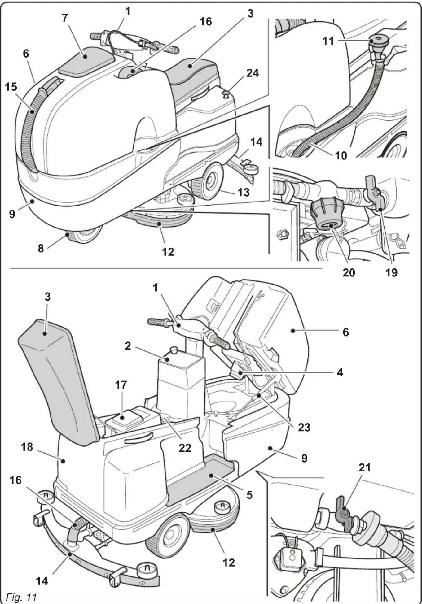
5.1 - GETTING TO KNOW THE MACHINE (Fig. 11)
1) Driving handlebars.
2) Control console.
3) Seat.
4) Suction unit.
5) Foot rest.
6) Recovery water tank.
7) Recovery water tank cover.
8) Directional wheel.
9) Clean water tank.
10) Clean water filling opening.
11) Water intake tube.
12) Brushes unit.
13) Traction wheels.
14) Squeegee.
15) Recovery water drain hose.
16) Squeegee water aspiration hose.
17) Battery charger (optional).
18) Protective battery guard.
19) Water regulation tap.
20) Water filter.
21) Clean water drainage tap.
22)Operator presence sensor.
23) Gas spring.
24) Emergency arrest button.
5.2 - MACHINE CONTROLS (Fig. 12)
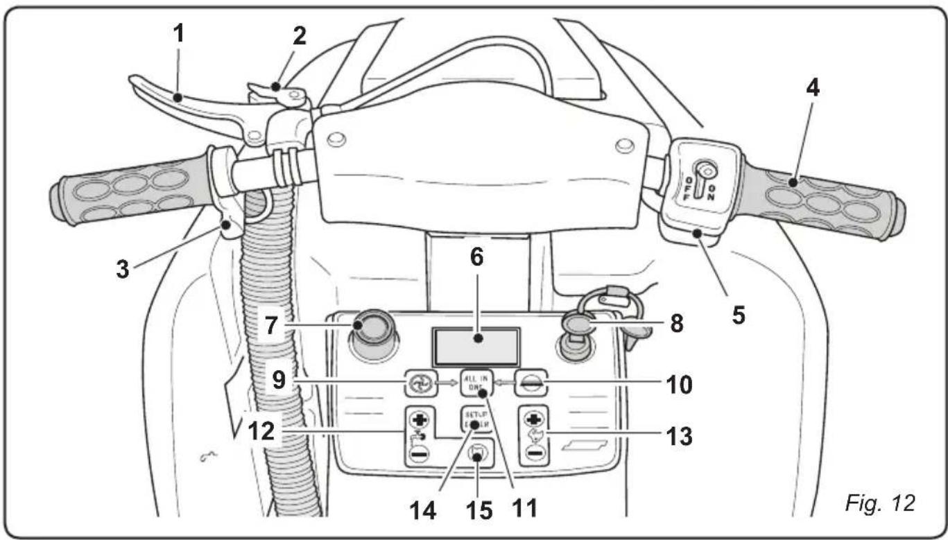
1) Brake lever.
2) Parking brake lever locking device.
3) Movement direction selector.
4) Accelerator.
5) Solution pump ON/OFF.
6) Backlit display.
7) Acoustic signal.
8) Starter key.

9) Suction activation button.

10) Brushes button.
11) "ALL IN ONE" automatic cycle start button.

12) Solution quantity adjustment buttons.

13) Operating speed adjustment buttons.
14) "ENTER SETUP" button for changing screen and configuration.
15) Detergent % adjustment (optional).
6.1 - DESCRIPTION OF THE CONTROLS
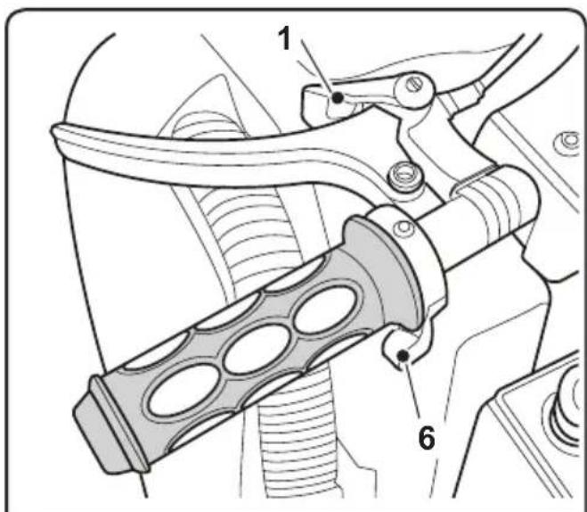
6.1.a - Left-side handlebar controls (Fig. 13)
1) Brake lever
Pull this lever (1) to activate the brake on the frontal wheel.
2) Parking brake
In order to engage the parking brake, pull the lever (1) to the end of its stroke and engage the locking device (2). This locks the lever (1) in place.
In order to release the brake, pull the lever (1) and press the locking device (2) outwards. This will release the lever (1).
3) Movement direction selector

NOTE:
The movement direction selector is only enabled while the operator is seated in the driver's seat.
The selector is made up of two buttons:
-
Press button (3a) to enable "FORWARD" movement, "↑" appears on the display. Press button (3b) to enable "REVERSE" movement, "↓" appears on the display.
-
Press both buttons simultaneously to disable the selected direction of movement and leave the machine in neutral. "N" appears on the display.
6.1.b - Right-side handlebar controls (Fig. 13)
4) Accelerator
Turn the handle (4) to activate the machine's movement and to increase or decrease the speed.
5) Solution pump ON/OFF
Turn the switch (5) to "ON" in order to enable the pump; turn the switch (5) to "OFF" in order to disable the pump.
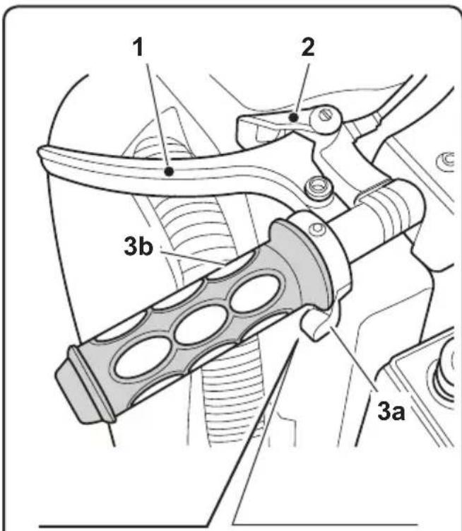
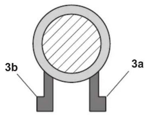
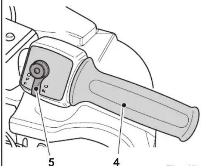
Fig. 13
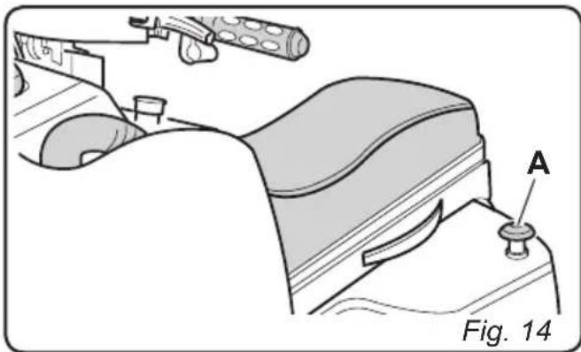
6.1.c - Emergency button (Fig. 14)
When pressed, this button impedes the machine from functioning by disconnecting its electrical power. In order to disengage the button (A), turn it in the direction indicated by the arrow on its head.

WARNING:
Only use the EMERGENCY button (A) in the event of actual necessity. Do not use it to shut off the machine: this could lead to serious machine malfunctions.
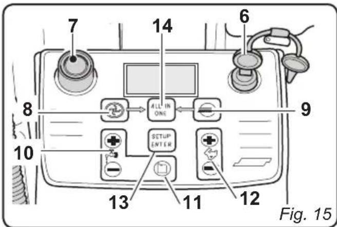
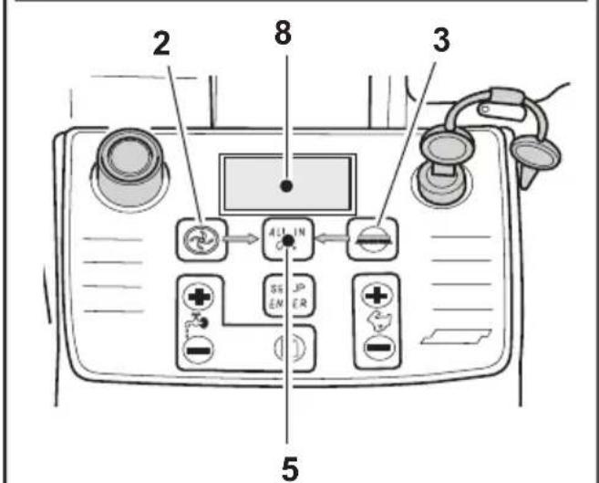
6.1.d - Control panel (Fig. 15)

NOTE:
Buttons (8), (9), (10), (11), (12), (13), (14) are only enabled while the operator is seated in the driver's seat with the key (6) turned to the "ON" position.
6) Ignition key
Turned in a clockwise direction to "ON", it powers the circuits, enabling machine operation.
Turned in an anti-clockwise direction to "OFF", it disconnects power to the circuits and can be removed.
7) Acoustic signal (Fig. 15)
- Press button (7) to activate the acoustic signal.
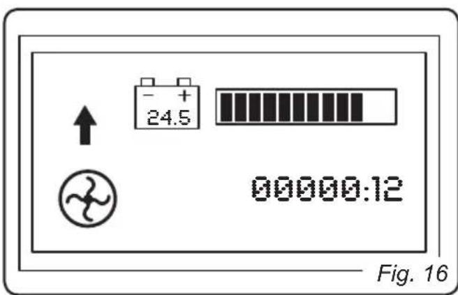
- Press this button to activate the suction unit. If forward movement or neutral are enabled, the squeezegee will be lowered.
Press the suction activation button again to deactivate the suction unit. The squeezee will be raised and the symbol on the display will turn off.
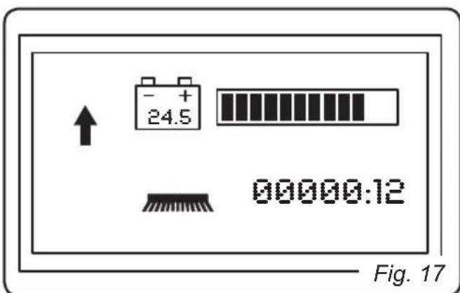
9)Brushes button

(Fig. 17)
- Press this button to lower the brush unit.
- The brushes will turn when the machine moves forwards or backwards and they stop turning when the machine is not moving.
- Press this button again to stop the brushes and raise the brush unit. The symbol on the display will turn off.

10) Solution quantity adjustment Press the (+) or (-) buttons to display the following screen;
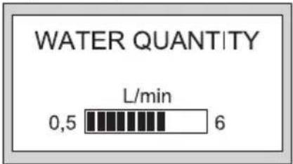
use the (+) and (-) buttons to increase or decrease the water flow. The flow can be adjusted between a minimum of 0 and a maximum of 6 litres/min.
11) Detergent quantity adjustment (optional)

Press this button to display the following screen;
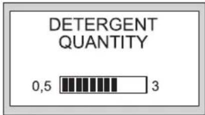
use the (+) and (-) buttons to increase or decrease the detergent flow. The flow can be adjusted between a minimum of 0.5% and a maximum of 3% .
(12) Operating speed adjustment

Press the (+) or (-) buttons to display the following screen;
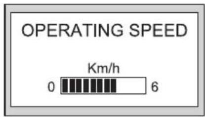
use the (+) and (-) buttons to increase or decrease the operating speed. The speed can be adjusted between a minimum of 0 and a maximum of 6km / h .
13) "ALL IN ONE" automatic cycle
Press this button to enable the automatic cycle.
This cycle provides for the activation/
deactivation of the machine's functions in their proper sequence; the sequences are the following:
- Press the button;
- The brushes are lowered;
- Engage forward movement. The machine moves, the brushes begin to turn and the solution is dispensed.
- After about 1 second, the squeezegee is lowered and then the suction unit is activated.
Once the cleaning cycle has been completed, press the button again to deactivate the automatic cycle. The brushes will stop moving and will be raised, solution dispensing will cease and the suction unit will shut off after 5 seconds, in order to suction any remaining liquid from the floor.
Button with two functions:
- If pressed once, it allows the operator to view the configuration screens.
- If pressed and held down for three seconds, it allows for access to the data insertion screen, thereby allowing the operator to insert and save new machine settings.
Viewing the working environment screens
- Turn the key to its "ON" position. The following screen will appear on the display:
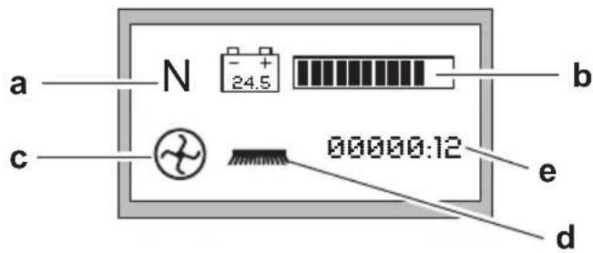
a) Directional movement enabled:
= Forward movement
= Reverse movement
N = Neutral
b) Battery charge status, the dark parts of the scale indicate the remaining battery life.
c) Suction unit in function. Indicates that button (8) has been pressed and that the suction unit is in function.
d) Brushes in function. Indicates that button (9) has been pressed and that the brushes are enabled for function.
e) Indicates the operating time of the drive motors.
Press the SETUP/ENTER button to display the following screen:
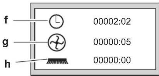
f) View machine activation time (key turned to "ON").
g) View suction unit activation time.
h) Brush rotation time.
Press the SETUP/ENTER button to display the following "CONTARESA" screen:
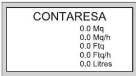
Mq Displays the area (in m 2) washed since the last reset (brushes in function).
Mq/h Indicates the average area (in m 2) washed per hour.
Ftq Displays the area (in Ft ^2 -square feet) washed since the last reset (brushes in function)
Ftq/h Indicates the average area (in Ft 2) washed per hour.
Litres Indicates how many litres of solution have been used.
Press the SETUP/ENTER button to display the following screen:
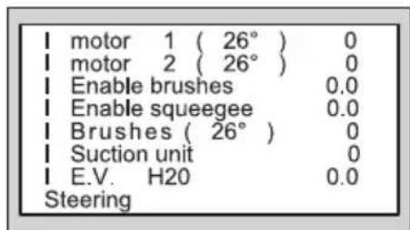
This screen displays some of the parameters relative to the absorption of the various components and their temperatures. This screen can be enabled by setting the "Data viewing" field in the data insertion screen to "1".

NOTE:
Press the SETUP/ENTER button to return to the initial screen.
Viewing screens in the data insertion environment
Press the SETUP/ENTER button for a few seconds to display the following screen:
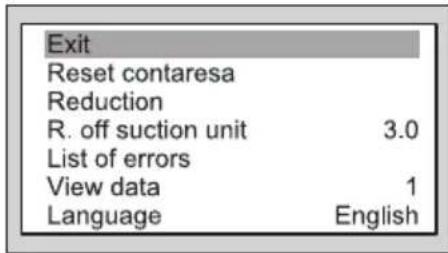
Press the button or the button to scroll through the various items and select the desired item. Press the SETUP/ENTER button to access the function.
List of functions:
Exit
Select this function and then press the SET-UP/ENTER button to exit the data insertion environment.
Reset Contaressa
Select this function then press and hold down the SETUP/ENTER button for a few seconds. The data contained in the "contaresa" screen will be reset and the message "CONTARESA RESET" will appear on the screen.
Reduction
This function is necessary for the contaresa. The cleaning tracks will overlap from one machine passage to the next and therefore the calculated yield is not exact.
For this purpose, a reduction percentage can be configured (set to 0 by default; 5% is recommended).
Suction unit off delay
This function allows for the suction unit's shutdown to be delayed after the relative shutdown button has been pressed.
It serves the purpose of allowing the water present within the tube to be suctioned completely.
Select the function and then press the

button to increase the time or the ton to decrease it.

but-
Once the desired time has been set, press the SETUP/ENTER button to confirm the selection.
Errors list
Select this function and then press the SET-UP/ENTER button to display the list of the errors encountered since the last time the list was reset.
Press the or button to scroll
through the list. Press the "SETUP/ENTER" button to exit list and return to the previous screen.
View data .X (X = 0 or 1)
Select this function and then press the SET-UP/ENTER button to modify the function then
press the button or the button to enable or disable data viewing.
Finally, press the "SETUP/ENTER" button to confirm the setting:
0 = Viewing disabled.
1 = Viewing permitted.
Languagexxxxxxxxxx Select the function then press the SETUP/ ENTER button to display the available lan
guages. Press the button or the button to scroll through the list. Press the SETUP/ENTER button to confirm the selected language.
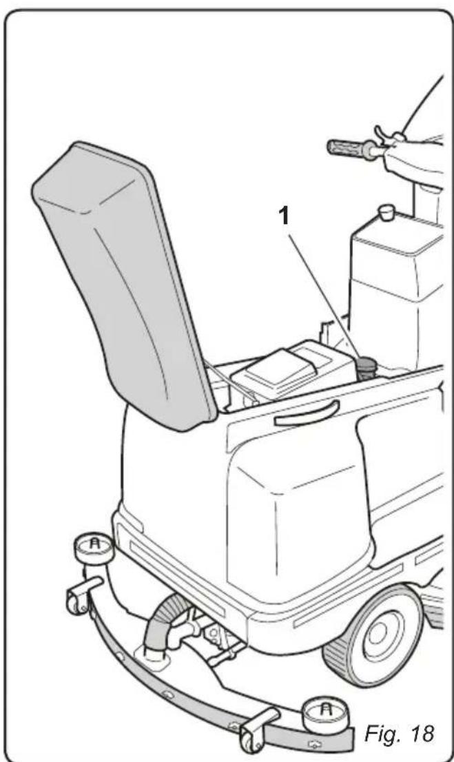
7.1 - SAFETY DEVICES
(Fig. 18)

WARNING:
The machine is equipped with an operator presence sensor (1); this sensor blocks all of the machine's functions and sets the machine in neutral whenever no operator is present in the driver's seat.
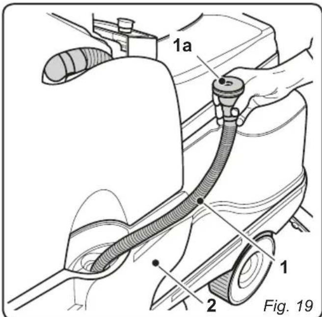
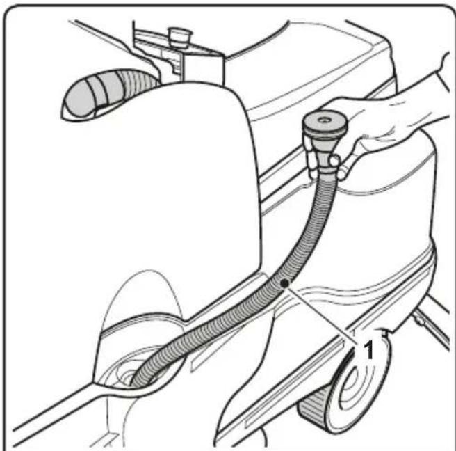
8.1 - FILLING THE TANK
(Fig. 19)

WARNING:
Only add clean mains water to the tank at a temperature no greater than 50^ .
- Extract the supplied tube (1) and connect its end (1a) to a tap, leaving the other end in the tank.
- Turn on the tap and fill the tank (2).
- Pour liquid detergent into the tank or, in the case of the optional metering system, check the level of detergent in the detergent tray.

NOTE:
Use non-foamy detergents only. For the quantities, follow the instructions provided by the detergent manufacturer according to the type of dirt.

DANGER:
- In the event of eye or skin contact with the detergent, or ingestion of the detergent, see the detergent manufacturer's usage and safety data sheet.
- After having filled the tank, insert the end (1a) into the tank's opening.
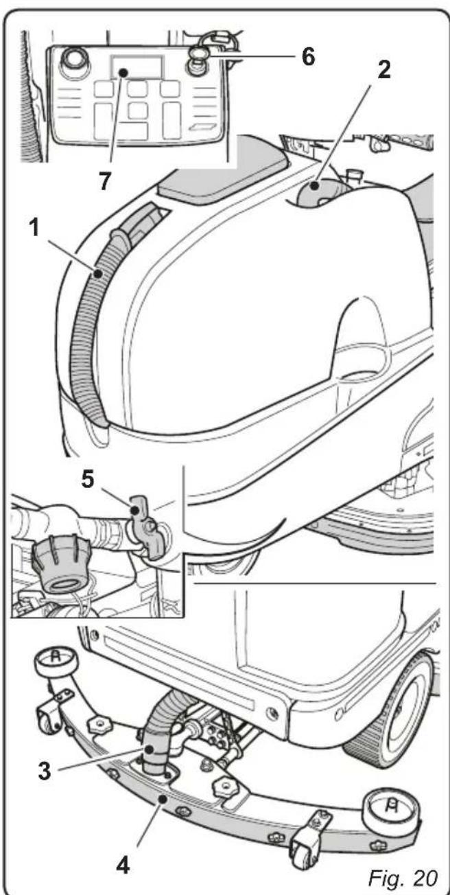
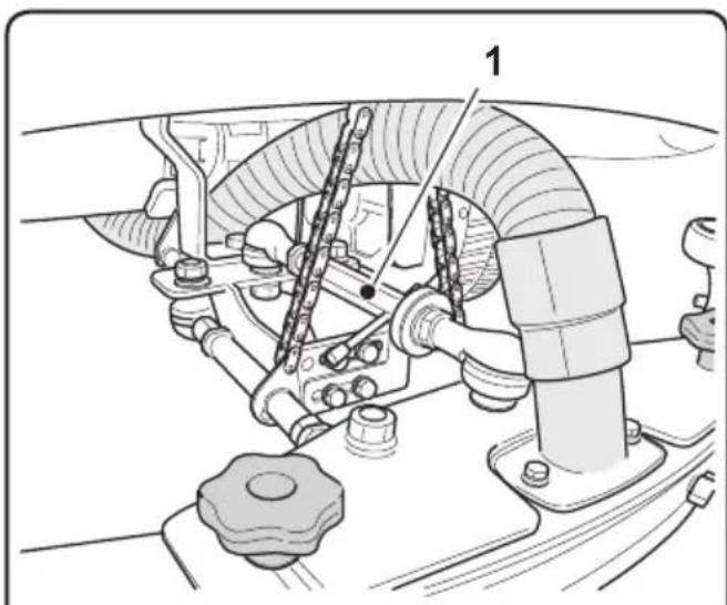
9.1 - OPERATION (Fig. 20)
9.1.a - Checks before use
- Check that the recovery tank's drainage tube (1) is properly connected and sealed.
- Check that the squeezegee's water suctioning tube (2) is properly inserted into the recovery tank.
- Check that the coupling (3) on the squeezegee (4) is not obstructed and that the tube is properly connected.
- Make sure that the tap (5) is open.
- Check the charge status of the batteries by turning the key (6) to its "ON" position and checking the charge indication on the display (7).
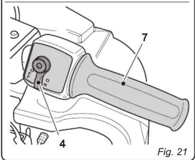
9.1.b - Preparing the machine and choosing the cycle (Fig. 21)
- Sit in the driver's seat and release the parking brake (1).
Working cycle:
- The machine can perform 4 working cycles:
Drying only cycle:
- To perform the drying cycle only, press button (2) The aspirator starts up.
Brushing only cycle:
- In order to perform the brushing cycle alone, press the button (3) to predispose the machine for the rotation of the brushes; the brushes will rotate once the machine begins to move.
Washing, brushing cycle:
- Press the button (3) to predispose the machine for the rotation of the brushes and turn the lever (4) to its "ON" position to predispose it for water dispensing. The brushes will begin to rotate and the machine will begin to dispense water (only with forward movement) once the machine begins to move.
Washing, brushing, drying cycle:
- Turn the lever (4) to its "ON" position to predispose the machine for dispensing water.
Press the "ALL IN ONE" button (5) to activate the automatic cycle.
9.1.c - Using the machine (Fig. 21)
-
After having started the machine and chosen the type of cycle, use the button (6) to engage the desired movement direction.
-
Use the accelerator (7) to begin the cleaning operations.

NOTE:
Release the accelerator to stop the rotation of the brushes and the dispensing of water.

NOTE:
Proper floor cleaning and drying is performed by driving the machine forwards. When driving in reverse, the squeezegee is raised and the suction unit, for removing the water from the floor, is deactivated.
- If necessary, use the relative buttons to adjust the amount of cleaning solution.
- Check the charge status of the batteries on the display (8).

NOTE:
After the key has been in its "ON" position for a few seconds and no function has been activated, the machine will go into STAND-BY in order to save energy; the following message will be shown on the display:
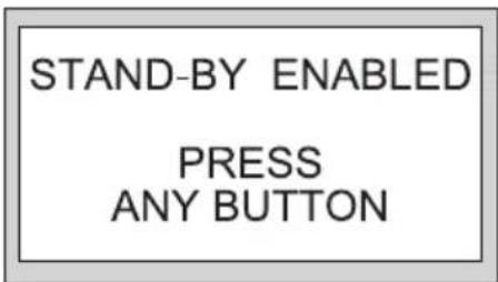
Press any key to exit STAND-BY mode.

DANGER:
When the operator gets off the machine, the machine goes into neutral. For this reason the parking brake MUST be engaged, as indicated in the "left side handlebar controls" section.
9.1.d - Alarms during function
While the machine is in function, the following alarms may occur, with relative messages appearing on the display:
Solution tank empty:
- Indicates that the mixture of detergent and water in the tank has run out. The brushes will stop and will be raised, the suction unit will continue to function for a few seconds before stopping and the squeezegee will be raised.
- In order to eliminate the alarm, fill the tank and then press the "SETUP/ENTER" button.
Recovery tank almost full:
- Indicates that the level of the liquid present in the recovery tank has reached the alarm threshold; it is possible to continue working, but it is recommended to bring the machine to the water drainage station as soon as possible in order to drain the recovery tank as indicated in the relative section.
Recovery tank full:
- Indicates that the liquid in the recovery tank has reached its maximum level (safety sensor); the suction unit will automatically shut off and the squeezegee will be raised.
- Bring the machine to the water drainage station and drain the recovery tank as indicated in the relative section.
Battery charge low
- Indicates that the charge level of the batteries is running out and that work must therefore be concluded in order to bring the machine to the battery charging station as soon as possible.
The operating functions remain active.
Battery drained
- Indicates that the batteries are completely drained; all of the operating functions will be deactivated, leaving only the drive function enabled.
Bring the machine immediately to the battery charging station.

NOTE:
If the machine continues to move while the alarm is active, before the batteries run out definitively another safety alarm will be activated which blocks all of the machine's functions.
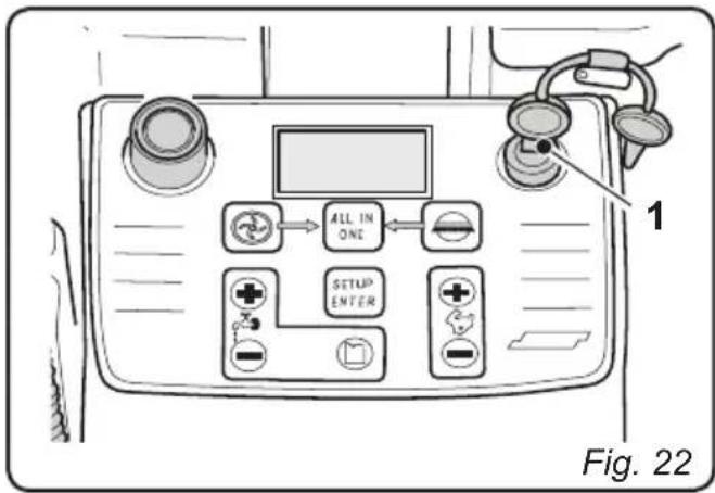
9.1.e - End of use and shutdown (Fig. 22)
- Once all of the cleaning operations have been completed, shut off, in sequence, the rotation of the brushes and the suction unit, using the relative controls according to the type of cycle being employed. Otherwise, if performing an automatic cycle, press the "ALL IN ONE" button.
- Turn the key (1) to its "OFF" position.
- Engage the parking brake as indicated in the "left side handlebar controls" section.
- Empty and wash out the recovery tank and the solution tank as indicated in the relative sections.
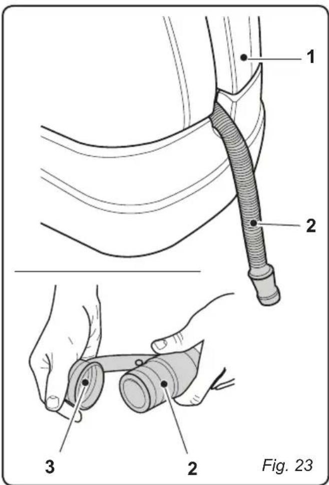
10.1 - DRAINING THE RECOVERY WATER (Fig. 23)
At the end of the washing cycle or when the recovery water tank (1) is full, it is necessary to empty the tank by proceeding as follows:

NOTE:
To dispose of the recovery water, comply with the standards in force in the country in which the machine is used.
- Position the machine near to a drain outlet.
- Disconnect the tube (2) from the tank (1).
- Remove the cap (3) from the hose (2) and drain all the water contained in the tank.
11.1 - MAINTENANCE AND CLEANING

WARNING:
For information and warnings regarding maintenance or cleaning, follow the information given in the "General warnings during maintenance" in chapter 1 in this manual.
OPERATIONS TO PERFORM DAILY
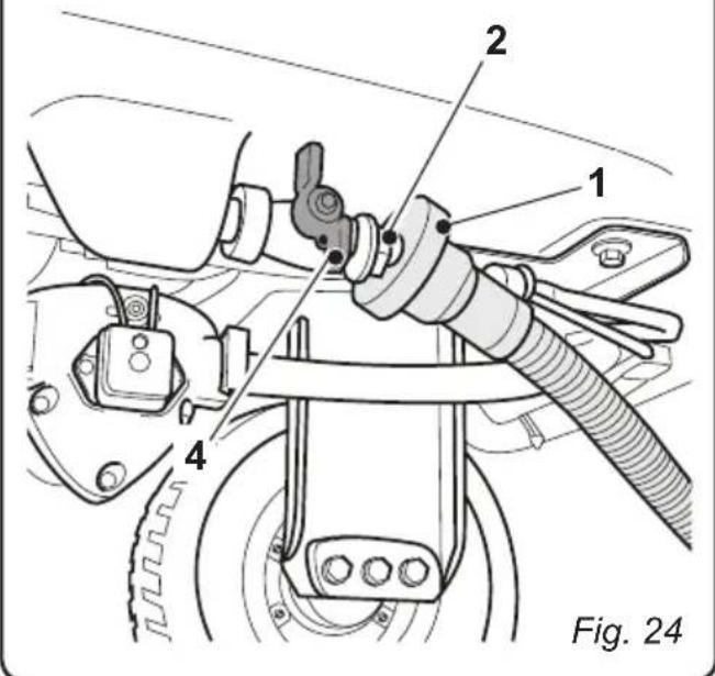
11.1.a - Emptying and cleaning the clean water tank (Fig. 24)

WARNING:
Once all of the cleaning operations have been completed, it is necessary to rinse the clean water tank out in order to prevent deposits or encrustations.
After draining the recovery water tank, drain the clean water tank as follows:
- Position the machine over a drain outlet.
- Remove the water intake tube (1) from the tank.
- Insert the upper part of the tube (1) into the drain connector (2) beneath the tank (3).
- Open the tap (4) and let the water contained in the tank drain out completely.
- Leave the drainage tap open and wash out the inside of the tank, pouring in clean water from the upper opening.
- Once the cleaning operation has been completed, close the tap (4) and reconnect the tube (2) to its proper lodging.
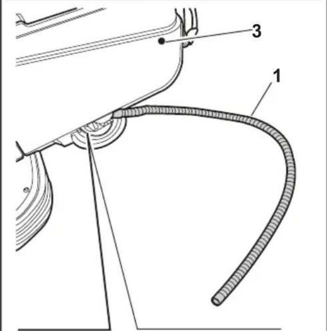
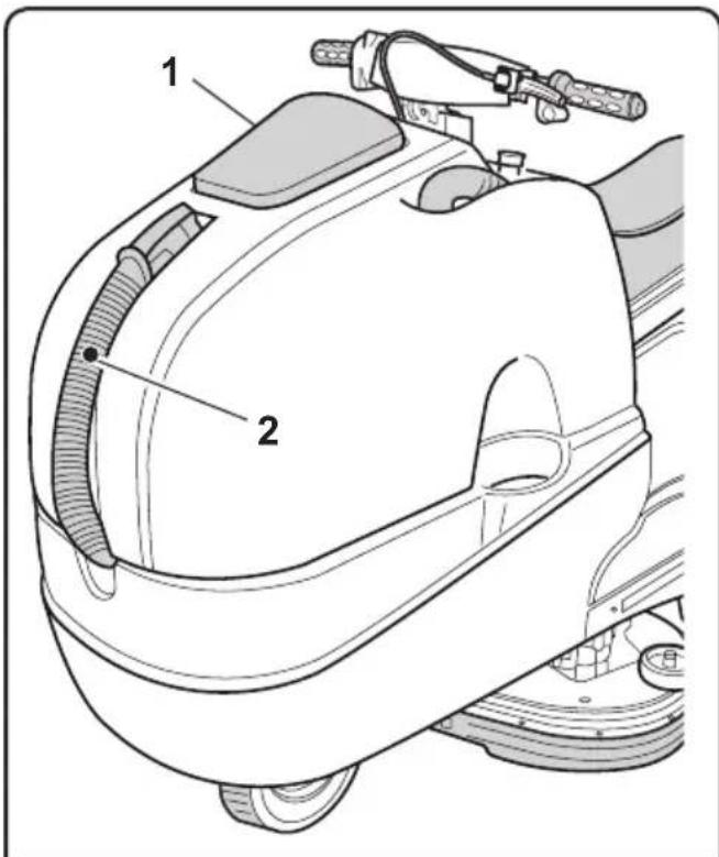
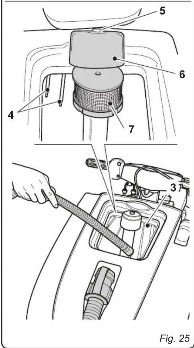
11.1.b - Cleaning the recovery water tank (Fig. 25)

WARNING:
At the end of the washing operations, it is compulsory to clean the recovery water tank to prevent deposits or scaling and the proliferation of bacteria, odours or mould.
- Drain the recovery water as shown in the relative paragraph, positioning the machine over a drain outlet.
- Remove the cover (1).
- Leaving the hose (2) lowered and the cap off, add water through the upper opening (3), cleaning the inside of the tank until clean water comes out of the drain hose.
- Clean the level sensors (4) with a damp cloth, taking care not to damage them.
- Reassemble all of the parts by performing these operations in the opposite order.
- Unscrew the Allen screw (5) and remove the filter cover (6).
- Remove and clean the suction filter (7), removing any pieces of paper, wood, etc., which may be obstructing it.
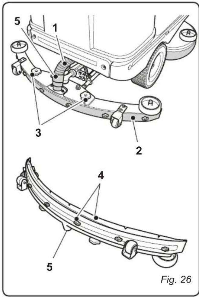
11.1.c - Cleaning the wiper (Fig. 26)
In order to clean the squeegee correctly (1), it is necessary to remove it as follows:
- Disconnect the hose (1) from the squeegee (2).
- Loosen the knobs (3) and remove the squeezegee (2).
- Wash the squeezegee and in particular the rubber blades (4) and the inside of the aspiration connector (5).

NOTE:
If, during washing, it is clear that the rubber blades (4) are damaged or worn, it is necessary to replace them or turn them over.
- Replace all the components in reverse order.
OPERATIONS TO PERFORM WEEKLY
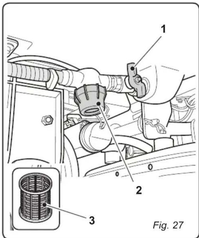
11.1.d - Cleaning the clean water filter (Fig. 27)
- Close the tap (1).
- Unscrew the transparent filter cover (2) and remove the filter (3).
- Clean the filter (3) in running water. If it is blocked, replace it.
- Reassemble everything, performing the operations in the opposite order, and open the tap (1).
OPERATIONS TO BE PERFORMED EVERY 3 MONTHS
11.1.e - Check the wear status of the steering chain (Fig. 28)
- Check the wear and corrosion status of the chain (1) found beneath the machine near the front wheel.
If the chain appears corroded, it must be replaced.
Contact the technical assistance service.
OPERATIONS TO PERFORM WHEN NECESSARY
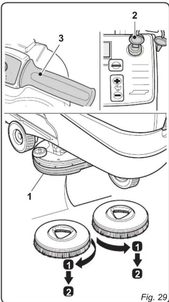
11.1.f - Replacing the brushes (Fig. 29)
The brushes must be replaced whenever they appear worn or whenever their bristles are shorter than 2cm . They must also be replaced based on the type of flooring to be cleaned; in order to replace them, perform the following operations:
- Insert a hand beneath the brush support unit (1). In order to detach the brush, turn it quickly and forcefully in the opposite direction from that in which it rotates during normal function.
- Place the new brushes beneath the brush support unit (1).
- Get into the driver's seat and turn the key (2) to its "ON" position.
- Engage a movement direction.

- Press the button to enable brush rotation; the brush unit will be lowered.
- Turn the accelerator handle (3) slightly. The brush support flanges will begin to turn, thereby connecting with the brushes.
Release the handle (3).
- Press the button again and turn the key (2) to its "OFF" position.
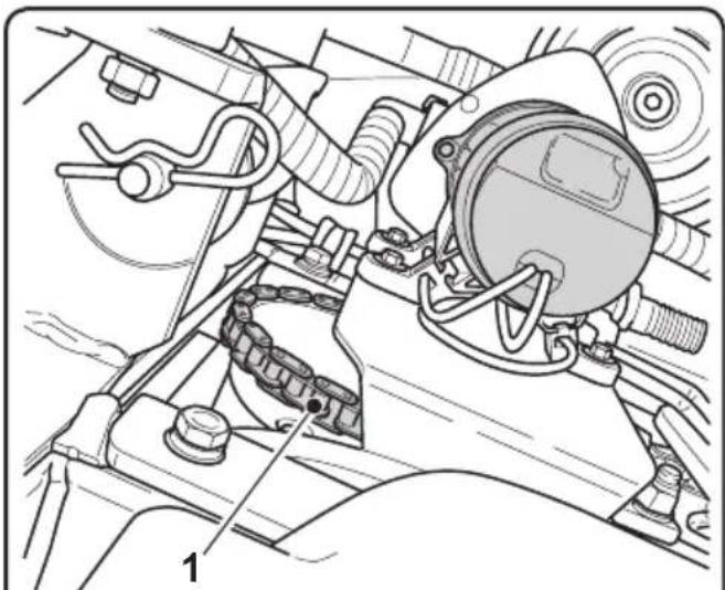
Fig. 28
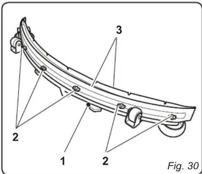
11.1.g - Replacing the squeezegee rubber blades (Fig. 30)
When it becomes clear that drying the floor is difficult or traces of water remain on the floor, it is necessary to check the wear on the squeegee rubber blades (1):
- Remove the squeegee unit (1) as indicated in the "Cleaning the squeegee" paragraph.
- Loosen the finned nuts (2) and remove the rubber blades (3).

NOTE:
When the rubber blades (3) are worn on one side, on one occasion they may be turned over.
- Replace or turn over the rubber blades (3) without inverting them.
- Replace all the components in reverse order.

NOTE:
Two types of rubber are available: Para rubber for all types of flooring and polyurethane rubber for workshop floors with oily residues.
11.1.h - Adjusting the pressure of the squeezegee (Fig. 31)

- Start up the machine and press the button.
The wiper unit will be lowered. - Engage the machine's forward movement, move it a few metres, engage the parking brake and get off the machine.
- Use the threaded bar (1) to adjust the squeezeges' (2) contact with the floor. Turn it clockwise for increased contact and counter clockwise for less contact.
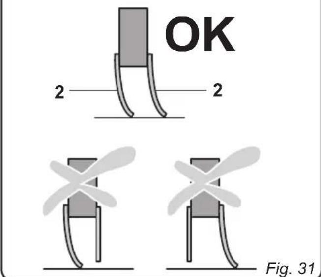

NOTE:
When the squeezegee is making proper contact with the floor, there will be no streaking on the floor during machine function and the entire length of the squeezegee will be in contact with the floor.
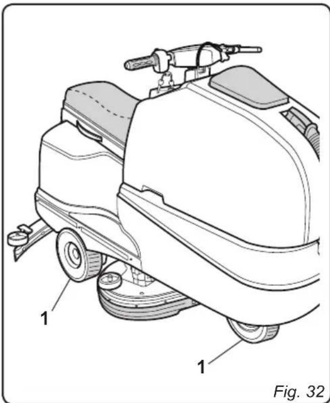
11.1.i - Checking the wear status of the three wheels (Fig. 32)
- Check the wear status of the three wheels (1) periodically; if they appear worn or damaged, contact a technical service centre in order to have them replaced.

DANGER:
Operating the machine with worn or damaged wheels poses a danger to the operator as the machine could have less traction when turning.
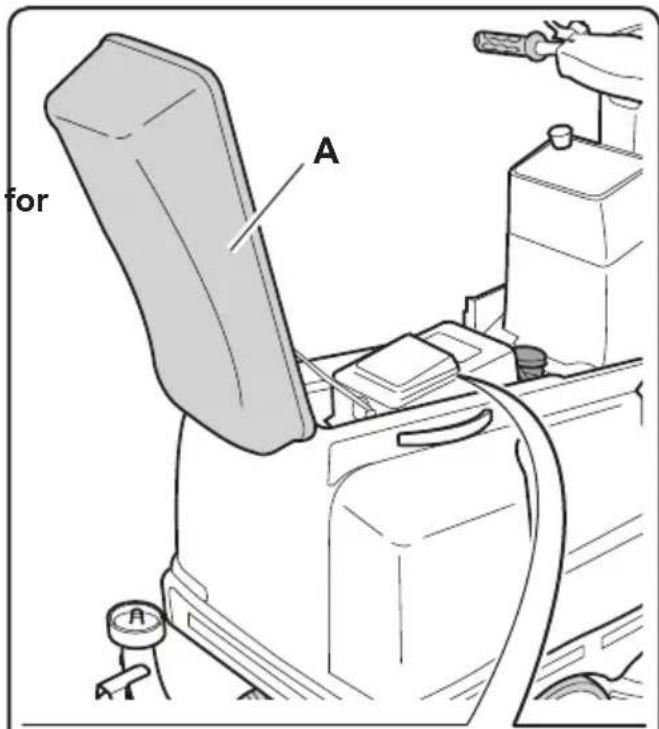
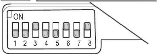
11.1.1 - Battery charger configuration (Fig. 33)

WARNING:
The machine comes pre-configured use with "Sonnenschein" gel batteries.
- Lift the seat (A).
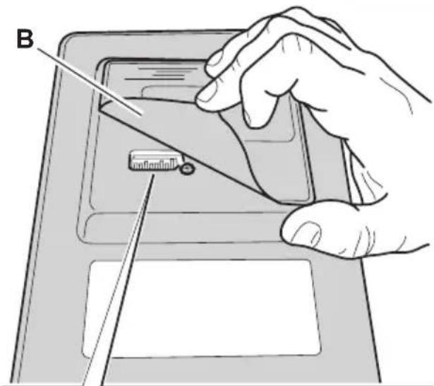
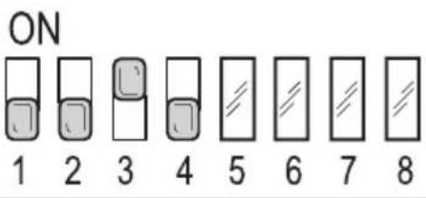
Standard configuration with Sonnenschin gel batteries
- Lift the cover (B) and check that the switches (1 - 2 - 3 - 4) are set to the configuration shown in the diagram (C).
Perform the following operations to modify the configuration:
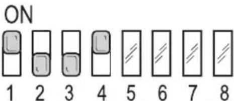
Configuration for gel batteries other than the Sonnenschein typology
- Lift the cover (B) and check that the switches (1 - 2 - 3 - 4) are set to the configuration shown in the diagram (D).
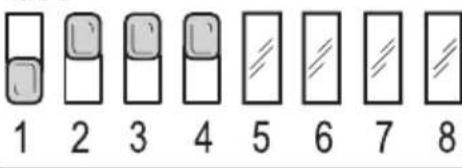
Configuration for acid batteries
- Lift the cover (B) and check that the switches (1 - 2 - 3 - 4) are set to the configuration shown in the diagram (E).

WARNING:
Only modify switches (1 - 2 - 3 - 4); do not alter the positions of switches (5 - 6 - 7 - 8).


ON
Fig. 33
TROUBLESHOOTING
| PROBLEM CAUSE | SE SOLUTION | |
| The machine does not start up when the key is turned. | Low battery. Main fuse blown. | Check that the battery is charged. Replace the fuse found on the battery cable. |
| The brush doesn't turn. Operating speed set to "0" km/h. Movement set to neutral. | Increase the operating speed. Engage forward or reverse movement. | |
| The suction unit does not function. | Recovery tank full. Level sensors dirty. | Empty the tank. Clean the recovery tank's level sensors with a damp cloth. |
| The machine does dry properly, leaving traces of water on the floor. | Aspirator off. Aspiration tube blocked. Recovery tank full. Squeezegee rubber blades worn. | Start up the aspirator. Check and if necessary clean the aspiration tube that connects the squeezegee to the recovery tank. Empty the recovery tank. Replace or turn over the squeezegee rubber blades. |
| No water comes out. | Tank empty. The electric pump activation switch is not set to its on position. Tap closed. Filter clogged. Water flow set to 0 litres/minute. Pump solenoid valve not functioning. | Fill the tank. Turn on the switch. Open the tap beneath the machine. Clean the filter. Increase the water flow. Call technical assistance. |
| PROBLEM CAUSE SOLUTION | ||
| The machine does not move in working conditions. | Operating speed set to “0” km/h. | Increase the operating speed. |
| Operator not properly seated in the driver's seat. | Sit properly in the driver's seat. | |
| Movement direction not engaged. | Use the appropriate control to engage the desired movement direction. | |
| Operator presence sensor disconnected. | Make sure that the sensor's connection cables are properly connected. | |
| Operator presence sensor malfunction. | Call customer service to request replacement. | |
| Insufficient floor cleaning. Unsuitable brushes or detergent. | Brush worn. | Use brushes or detergents which are suitable for the type of floor or dirt to be cleaned. |
| Replace the brush. | ||
WIRING DIAGRAM
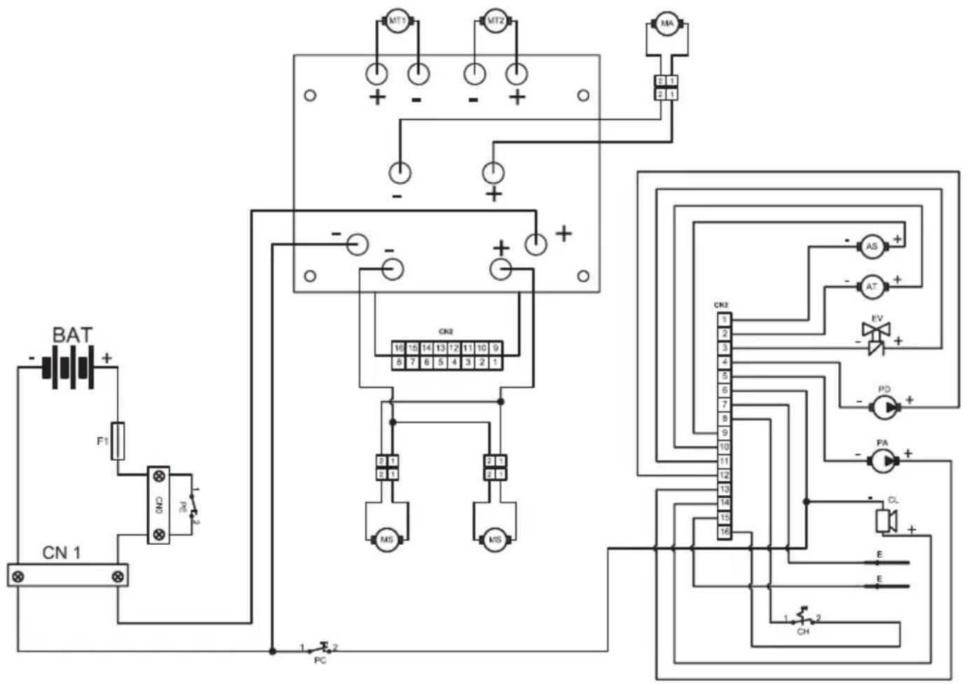
AS Brush actuator
AT Wiper actuator
BAT 24V battery
CL Buzzer
CN1 120A Plug socket
CN2 Card connector
CH Key
E Level sensor
EV H20 Solenoid valve
F1 100A fuse
MA Suction motor
MS Brush motor
MT1 Left drive motor
MT2 Right drive motor
PD Detergent pump
PA .Water pump
PE Emergency button
PC.Horn button
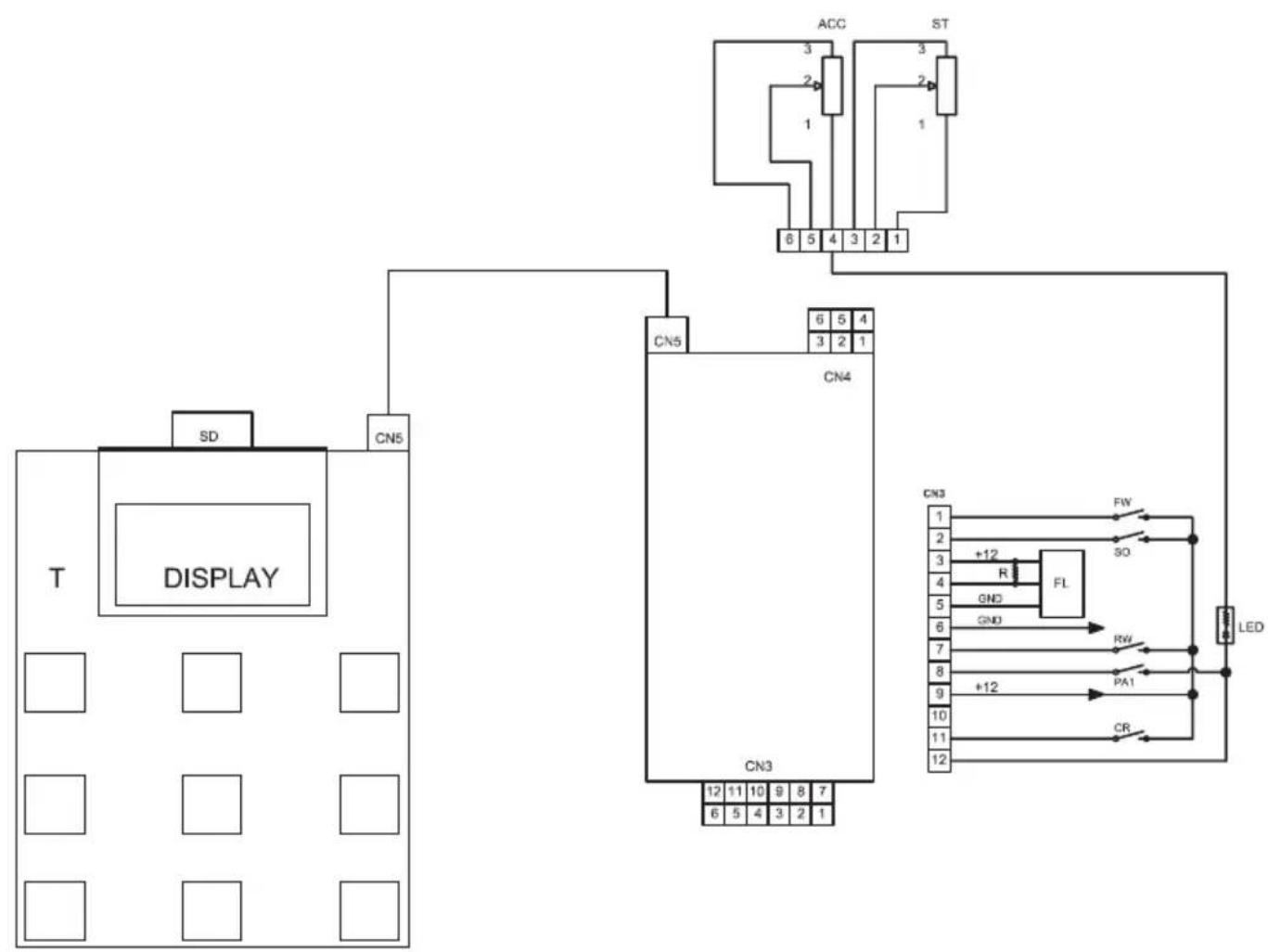
ACC Accelerator
FW .Forward gear
so .Operator presence sensor
RW .Reverse gear
PA1 .Water pump switch
FL . Flowmeter
CR Wheel sensor
ST Steering sensor
CN3 Signals connector
CN4 Handlebars connector
CN5 ......... Button panel connector
R 10Komh resistance
T .Button panel
Cher client,
Avancement. Traction avant/arriere
0 = Affichage desactive.
DIAGRAMA (ESQUEMA) ELETRICOS

AS Actuador escovas
ST Sensor directional
CN3 Conectores de sinais
CN4 Conector Guiador