BelliSlimo Cloud 50 - Boiler Tesy - Free user manual and instructions
Find the device manual for free BelliSlimo Cloud 50 Tesy in PDF.
Frequently Asked Questions - BelliSlimo Cloud 50 Tesy
User questions about BelliSlimo Cloud 50 Tesy
0 question about this device. Answer the ones you know or ask your own.
Ask a new question about this device
Download the instructions for your Boiler in PDF format for free! Find your manual BelliSlimo Cloud 50 - Tesy and take your electronic device back in hand. On this page are published all the documents necessary for the use of your device. BelliSlimo Cloud 50 by Tesy.
USER MANUAL BelliSlimo Cloud 50 Tesy
EN ELECTRIC WATER HEATER 6-9 Instructions for use and storage
natural_image
White TESY water heater with control panel and brand logo (no visible text or symbols on body)ВАЖНИ ПРАВИЛА
-
This technical description and instructions manual was prepared in order to acquaint you with the product and the conditions of proper installation and use. These instructions were also intended for use by qualified technicians, who shall perform the initial installation, or disassembly and repairs in the event of a breakdown.
-
Following the current instructions will primarily be of interest to the consumer, but along with this, it is also one of the warranty conditions, pointed out in the warranty card, so that the consumer can benefit from the free warranty services. The producer is not responsible for damages in the appliance that have appeared as a result of operation and/or installation not corresponding to the instructions here.
-
The electric water heater complies with the requirements of EN 60335-1, EN 60335-2-21.
- This appliance can be used by children aged from 8 years and above and persons with reduced physical, sensory or mental capabilities or lack of experience and knowledge if they have been given supervision or instruction concerning use of the appliance in a safe way and understand the hazards involved.
- Children shall not play with the appliance.
- Cleaning and user maintenance shall not be made by children without supervision.
Attention! Improper installation and connection of the appliance may make it hazardous for the health and life of consumers. It may cause grievous and permanent consequences, including but not limited to physical injuries and/or death. Improper installation and connection of the appliance may also lead to damage to the consumers' property /damage and/ or destruction/, or to that of third persons, as a result of, but not limited to flooding, explosion and/or fire.
Installation, connection to the main water and power supply, and putting into operation must be carried out by certified electricians and technical personnel certified in installation of this category of appliances, who have obtained their license in the state where the installation and commissioning of the appliance are carried out, and in compliance with its local legislation.
All alterations and modifications to the water heater's construction and electrical circuitry are forbidden. If such alterations or modifications are established during inspection, the appliance's warranty shall be null and void. Alterations and modifications shall mean each instance of removal of elements incorporated by the manufacturer, building in of additional components into the water heater, replacement of elements by similar elements unapproved by the manufacturer.
Mounting
- The water heater must only be mounted in premises with normal fire resistance.
- In the event the device is mounted in a bathroom, the selected location must exclude the possibility of water spray contact from the showerhead or portable showerhead attachment.
- The water heater is designed to operate only in closed and heated premises where the temperature is not lower than 4^ C and it is not designed to operate in a continuous protracted regime.
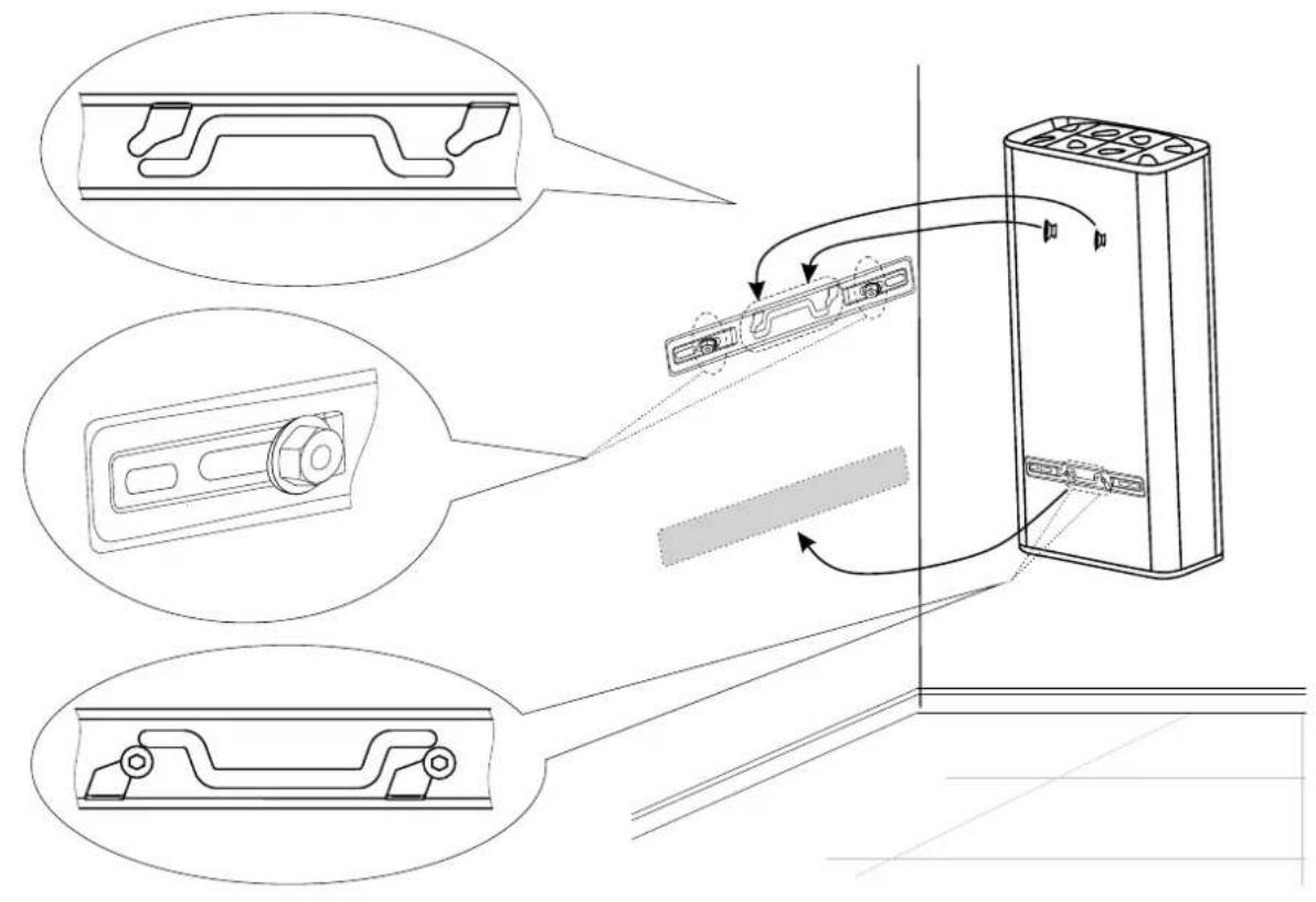
- When mounted on a wall - the device is suspended by means of the M8 bolts attached to the housing, which are installed on brackets pre-mounted and levelled with the wall. The load-bearing brackets and dowels for wall mounting are included in the kit.
Water heater connection
- The appliance is intended to supply hot water to household sites equipped with a piping system working at pressure below 6 bar (0,6 Mpa).
- .The safety return-valve must be mounted on the cold water supply pipe, in observance of the direction arrow stamped on its body, indicating the incoming water's direction. Additional stopcocks must not be mounted between the safety return-valve and the water heater.
Exception: If the local regulations (norms) require the usage of another protection valve or mechanism (in accordance with EN 1487 or EN 1489), then it must be bought additionally. For mechanisms operating in accordance with EN 1487 the announced operational pressure must be no more than 0.7 MPa. For other protection valves, the pressure at which they are calibrated must be 0.1 MPa lower than the one marked on the appliance's sign. In these cases the safety valve which the appliance is supplied with should not be used. - The safety valve and the pipe between the valve and the water heater must be protected from freezing. During hose draining - its free end must be always open to the atmosphere (not to be immersed). Make sure that the hose is also protected from freezing.
- In order to secure the water heater's safe operation, the safety return-valve must undergo regular cleaning and inspections for normal functioning /the valve must not be obstructed/, and for the regions with highly calcareous water it must be cleaned from the accumulated lime scale. This service is not provided under warranty maintenance.
- In order to prevent injury to user and third persons in the event of faults in the system for providing hot water, the appliance must be mounted in premises outfitted with floor hydro insulation and plumbing drainage. Don't place objects, which are not waterproof under the appliance under any circumstances. In the event of mounting the appliance in premises not outfitted with floor hydro insulation, a protective tub with a plumbing drainage must be placed under the appliance.
- During operation – regime of heating the water – water drops through the drainage opening of the protection valve are usual. The protection valve should be left open to the atmosphere. Measures should be taken to lead and collect the leakages in order to prevent damages.
- If the probability exists for the premise's temperature to fall below 0^ C, the water heater must be drained.
In the event you must empty the water heater, first you must cut off its power supply. The inflow of water from the water mains must first be terminated and the hot water tap of the mixing-faucet must be opened. The water tap 7 (fig 5) must be opened to drain the water from water tank. If there is no such tap build in the pipe line, than the water can be drain directly from inlet pipe of water tank after when you disconnect it from water main.
Connection to the electrical network
- Do not switch on the water heater unless you established it was filled with water..
- Upon connecting the water heater to the electric mains care must be taken to connect the safety lead.
- Models without power cord, the circuit has to be supplied with a safety fuse (16A) and with inbuilt device to ensure disconnection of all pole pieces in the conditions of over-voltage from category III.
- If the power supply cord (of models that have one) is damaged, it must be replaced by a service representative or a person with similar qualification, to avoid any risk.
- The power supply conductor insulation from fixed wiring must be protected from direct contact with the flange (in zone under the plastic panel). For example, insulating sleeving having temperature rating higher than 90 °C can be used.
- During the heating the appliance could produce a hissing noise (the boiling water). This is common and does not indicate any damage. The noise gets higher with the time and the reason for this is the accumulation of limestone. To remove the noise the appliance must be cleaned from limestone. This type of cleaning is not covered by the warranty.
Dear Clients,
The TESY team would like to congratulate you on your new purchase. We hope that your new appliance shall bring more comfort to your home.
II. TECHNICAL PARAMETERS
- Nominal volume, litres - see the appliance's rating plate
- Nominal voltage - see the appliance's rating plate
- Nominal power consumption - see the appliance's rating plate
- Nominal pressure - see the appliance's rating plate

This is not the water mains pressure. This is the pressure that is declared for the appliance and refers to the requirements of the safety standards.
- Water heater type – closed type accumulating water heater, with thermal insulation
- Daily energy consumption – see Annex I
- Rated load profile – see Annex I
- Quantity of mixed water at 40°C V40 in litres – see Annex I
- Maximum temperature of the thermostat - see Annex I
- Default temperature settings – see Annex I
- Energy efficiency during water heating – see Annex I
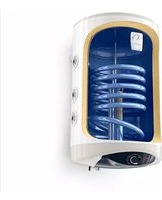
III. DESCRIPTION AND PRINCIPLE OF OPERATION
The appliance consists of a body, flange at the bottom side (for water heaters intended for vertical mounting) or at the sides (for water heaters intended for horizontal mounting), protective plastic panel and a safety-return valve.
- The housing consists of two steel tanks (water tanks) and a casing (outer shell) with heat insulation between them from an environmentally clean high-density polyurethane foam and a housing (outer shell) with thermal insulation placed in-between made of ecologically clean high density polyurethane, and two pipes with thread G½" for cold water supply (marked by a blue ring) and hot water outlet pipe (marked by a red ring).
The inner tanks, depending on the model, may be two types:
- Made of steel protected from corrosion by a special glass-ceramic or enamel coating;
• Made of stainless steel.
2. An electric heater and a magnesium protector are installed on each flange. The electric heater is used for heating the water in the tank and is operated by the thermostat, which automatically maintains the set temperature. The appliance has two built-in devices (for each of the water tanks) for overheat protection (thermoswitches) which switch off the respective heater from the mains when the water temperature raises too much.
3. The safety-return valve prevents the appliance's complete emptying if the cold water supply stops from the water mains. The valve protects the appliance from pressure increases higher than the allowed value during heating mode (an increase of temperature causes water expansion and therefore pressure increase) by releasing the excess pressure through the drainage opening.

The safety-return valve cannot protect the appliance in the event of water mains pressure that is higher than the pressure stated for the appliance.
IV. MOUNTING AND SWITCHING ON
Attention! Improper installation and connection of the appliance will make it hazardous with grave health consequences and may cause even death of users. It may also damage their property, that of third parties, as a result of flooding, explosion, fire. Installation, connection to the water mains and connection to power lines must be carried out by qualified technicians. A qualified technician means a person who has appropriate competencies pursuant to the regulations of the relevant state.
1. Mounting
We recommend the device to be mounted in close proximity to locations where hot water is used in order to reduce heat losses during transportation in the pipelines. If the device is mounted in a bathroom, it should be in such a place so as not to be poured with water from the showerhead or a portable showerhead attachment.
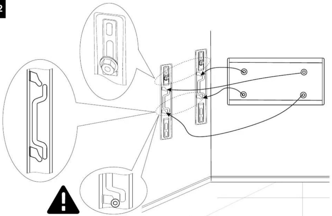
When mounted on a wall - the device is suspended by means of the M8 bolts attached to the housing, which are installed on brackets pre-mounted and levelled with the wall. The load-bearing brackets and dowels for wall mounting are included in the kit.
Vertical installation scheme - Fig. 4.1
Horizontal installation scheme - Fig. 4 2.
In order to prevent injury to the user and/or third persons in the event of faults in the system for hot water supply, the appliance must be installed in premises with floor hydro insulation and drainage to the sewerage. Under no circumstances should you place objects which are not waterproof under the appliance. If the appliance is installed in premises without floor hydro insulation, a protective tub with drainage to the sewerage must be in place under the appliance.

Note: The set does not include a protective tub and it should be chosen/purchased by the user.
2. Connecting the water heater to the water supply system
Fig. 5
Where: 1 - Inlet pipe; 2 - safety valve; 3 - reducing valve (for pressure in the water mains higher than 0.6 MPa); 4 - stop valve; 5 - funnel connected to the sewerage; 6 - hose; 7 - drain water tap.
Upon connecting the water heater to the water mains you must consider the indicative colour markings (rings) affixed to the pipes: blue for cold (incoming) water, red for hot (outgoing) water.

The mounting of the safety return-valve supplied with the water heater is obligatory. The safety return-valve must be mounted on the cold water supply accordance with the direction of the arrow stamped on its body, indicating the position of the incoming water.
Exception: If the local regulations (norms) require the use of another protection valve or device (which conforms to EN 1487 or EN 1489), then it must be purchased additionally. For device operating in accordance with EN 1487 the declared maximum operational pressure must be no more than 0.7MPa . For other protection valves, the pressure at which they are calibrated must be 0.1MPa lower than the one marked on the appliance's plate. In these cases the safety valve which the appliance is supplied with should not be used.

Other type of stopping armature is not allowed between the protection return valve (the protective device) and the appliance.

The presence of other (old) safety return-valves may lead to a breakdown of your appliance and they must be removed.

The attaching of the safety return-valve to threads longer than 10 mm is not allowed; otherwise this may damage the valve and therefore pose danger to appliance.

The safety-return valve and the pipe between the valve and the water heater must be protected from freezing. In case of hose draining its free end must be open to the atmosphere (not to be immersed). Make sure that the hose is also tied from freezing.
To fill the water heater with water first open the hot-water tap of the water-mixing faucet. Then open the cold-water tap of the water-mixing faucet. The appliance is full when a constant stream of water flows from the water-mixing faucet. Then close the hot water tap.
When you have to empty the water heater, first you must cut off its power supply. Then stop feeding water to the appliance. Open the hot-water tap of the water-mixing faucet. Open tap 7 (fig. 5) in order to drain the water from water tank. If there is no such tap built in the pipeline, than the water can be drained directly from the inlet pipe of the water tank, having it disconnected from the water mains prior to this
When removing the flange, it is normal for several litres of water, which have remained in the water tank, to be discharged.

Measures must be taken to prevent damages by the discharged water.
If the pressure in the water mains piping exceeds the value specified in paragraph I above, a pressure-reducing valve must be installed, otherwise the water heater will not be correctly operated. The manufacturer will not bear any liability for problems arising from improper operation of the appliance.
3. Connecting the water heater to the electrical mains

Make sure the appliance is full of water before switching on the electrical power supply.
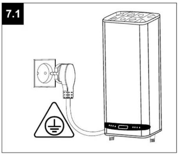
3.1. For models with a power cord with a plug, connection to the electrical mains is done by inserting the plug into an electrical socket.
Disconnection from the electrical mains is done by unplugging the power cord from the socket.

The electrical socket must be properly connected to a separate current loop that is provided with a safety fuse. It must be earthed.
3.2. Water heaters with a power supply cord without a plug
The appliance has to be connected to a separate current loop of the stationary electrical installation, and also it has to be provided with a safety fuse with nominal current of 16A (20A for power >3700W). The connection has to be permanent – with no plug connectors. The current loop has to be provided with a safety fuse and with an inbuilt device which would disconnect all poles in case of category III overvoltage.
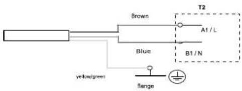
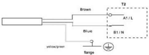
The connecting of the conductors of the supply cord of the appliance has to be carried out in the following way:
• conductor with brown insulation – to the phase conductor of the electrical installation (L)
- conductor with blue insulation – to the neutral conductor of the electrical installation (N)
- conductor with yellow-green insulation – to the safety conductor of the electrical installation (1)
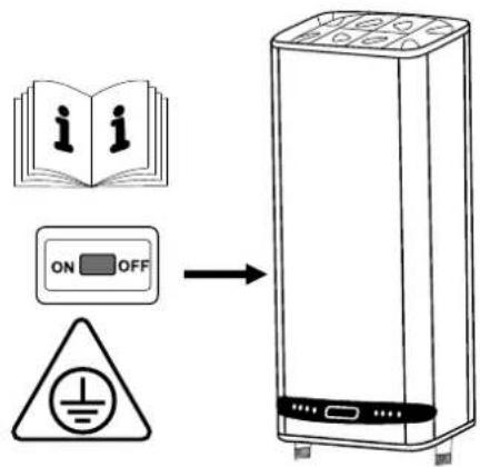
3.3. Water heaters without power cord
The appliance has to be connected to a separate current loop of the stationary electrical installation, provided with a safety fuse with nominal current of 16A (20A for power >3700W). Connection is done using copper single core (rigid) conductors – cable 3 x 2.5 mm ^2 for a total power of 3000W (cable 3 x 4.0 mm ^2 for power >3700W).
In the electrical circuit providing power supply for the appliance there has to an inbuilt device which would disconnect all poles in case of category III overvoltage.
To install the power supply wire to the water heater, remove the plastic cover (Fig.7.3).
Connect the power supply wire in compliance with the marking on the terminals, as it follows:
• the phase – to marking A or A1, L or L1;
• the neutral – to marking N (B or B1 or N1)
- The safety wire must be connected to the screw joint marked with ⊥
After installation, put the plastic cover back in its place!
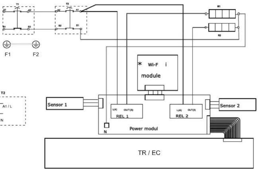
Explanations to Fig. 6:
T1, T2 - thermal circuit breaker; TR/EC - thermal regulator/ electronic control; R1, R2 - heating element; F1, F2 - flange; S1, S2 - sensor; Wi-Fi module (for models with Wi-Fi)
EN
V. ANTI-CORROSION PROTECTION - MAGNESIUM ANODE (FOR WATER HEATERS WITH WATER TANKS COVERED BY GLASS-CERAMIC OR ENAMEL COATING)
The magnesium anode provides additional protection to the water tank's inner surface from corrosion. It is an element undergoing wear and tear and is subject to periodic replacement, which is at the expense of the user. In view of the long-term and accident-free use of your water heater, the manufacturer recommends periodic inspections of the magnesium anode's condition by a qualified technician and replacement whenever required, and this could be performed during the appliance's technical preventive maintenance.
For replacements, please contact the authorized service centres or a qualified technician!
VI. OPERATION.
1. Switch on the electric water heater
Before initial start of the appliance, please make sure that the water heater has been correctly connected to the electrical network and that it is filled up with water. Switching on the water heater is done through the device incorporated in the installation, which is described in sub-item 3.3 of section IV, or by inserting the plug into an electrical socket (for models with cord with a plug).
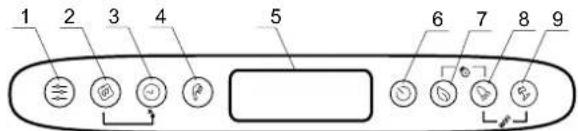
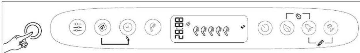
2. Description of the control panel of the appliance
text_image
1 2 3 4 5 6 7 8 9Button and element designation:
1 - Program selection button and activation of programming functions in the "Weekly Programmer" regime
2 - Button for selection of the day of the week.
3 - Time / period selection button in different modes
4 - Handset" button to select number of showers and activate the "Manual control" mode.
5 - LCD display.
6 - Device on / off button - Standby mode.
7 - ECO SMART, ECO NIGHT or ECO COMFORT mode selection button
8 - "BOOST" function selection button
9 - 6n / Off button for Vacation Mode
Possible combinations:
7 + 8 - Ⓛ "locking" of the panel
8 + 9 - ✉ Turning the Wi-Fi Module On or Off (Stand By Mode)
2 + 3 - Ⓧ Copy the status of the current cell
1 + 2 - Vertical to horizontal orientation of the display
3. Switching on the electronic operation of the appliance
Switching on is done by pressing button By doing so the display will show the mode which is to be used and, depending on the type of mode, the symbols described for each mode below.
Switching off the electronic operation is done by pressing button
4. Setting up and operation of the appliance
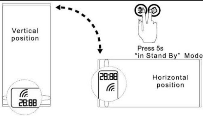
- Switching on and off the Wi-Fi module (for models with Wi-Fi).
Switching on and off the Wi-Fi module is done by simultaneously pressing the buttons + for minimum 10 seconds in stand-by mode, i.e. when the appliance is switched off from button When the Wi-Fi module is on, the display shows the following symbol
- Setting the time and day of the week
In order for the programme modes to work properly you must set the current time and day of the week. Setting up is done in stand-by mode, i.e. when the appliance is not switched on. Hold the button. The day of the week starts blinking in the weekday selection field. Using the button select the current day of the week. Press button to confirm the selection. The first two digits of the timer start blinking. Using the button set the time and confirm with. The second group of digits starts blinking. Again, using button set the minutes and confirm with button
●Vertical to horizontal orientation of the display
In order for the program modes to work correctly when installing the appliance horizontally, it is obligatory to select a "horizontal" mode of operation (horizontal orientation of the display). To switch between horizontal and vertical symbols and vice versa, you need to press and hold the two buttons + for 5 seconds when the water heater is a standby mode.

WARNING: Your TESY electric water heater is of the highest energy class. The class of the appliance in ECO mode is guaranteed only When the display nation is correct.
"Manual control" mode
Using button you can select the "Manual control" operating mode. The symbol and the countdown timer are shown on the display if the appliance is in a warm-up or clock mode, if the appliance is ready for use.
When you turn on the manual mode, the screen shows the last saved preset number of showers. The maximum number of showers that can be selected depends on the model and is shown in table 1.3.
• "Anti-freezing" function
The Anti-freezing function is active with the following modes: Manual control and Weekly Programmer.
To turn the Anti-freezing mode on, you need to press button ⏻ until to display the symbol ✧ appears.

WARNING: The electrical power supply of the device should be switched on. The safety valve and the pipe connecting it to the device must be secured against gter.
• "Weekly programmer" mode
By pressing button you can select one of the three built-in weekly program modes - P1, P2 or P3.
To set up the program you have selected, press and hold button to start setting it.
The device enters programming mode for the selected program. The program indicator (P1, P2 or P3) flashes on the display.
Step 1 - Choose a day of the week
Using button select the day of the week for which you will change the program.
Step 2 - Select the desired time
Using button select the desired time.
Step 3 – Select the desired amount of hot water
With button Select the number of showers to indicate the required amount of hot water for the desired time. You can choose *, 1, 2, ... number of showers by pressing the button
"*" means that the anti-freeze mode is selected, which is displayed with the symbol *.
By using the combination of buttons 📄 + 🕒 you may copy settings (number of showers) from the current hour to the next hour.
To do this, press and hold button and by pressing button move to the next hour (neighbouring cell), copying the selected number of showers.

A cell is provided in the hour chart for each hour of the day. The numbers below are guiding you.
Indication key:
- When the time cell is full there is a requirement for hot water at that time and the water will be heated depending on the number of showers selected.
□- if the time cell is empty, the device has no task set for that time
The changes made are confirmed by pressing button once and the appliance will exit the setup mode.
In case the buttons are not manipulated for a long time, the changes are automatically saved (even if they have not been confirmed).
Program modes - P1 и P2
For programs P1 and P2, you can select which day of the week, at what time what amount of hot water you need. The appliance calculates when to turn on in order to provide the required amount at the set time.
Example:
If you have set that you need to have hot water for 3 people on Wednesday at 18:00, the appliance will maintain that amount for a certain period of time and will then shut down.
Program mode - P3
For P3 programs, you can select the day of the week, the duration of operation of the appliance and the amount of hot water it needs to provide. The appliance switches on and tries to reach the set number of showers.
If you have set that on Wednesday at 18:00 you need to have hot water for 3 showers, the appliance will start heating the water at this time until it reaches the 3 showers set.
• ECO SMART, ECO NIGHT and ECO COMFORT mode
By pressing button you can choose between three modes:
ECO - ECO SMART,
EC1 - ECO COMFORT ((the lowest limit provides 2 showers, the upper limit generates economy).
EC2 - ECO NIGHT (SMART algorithm with night-time heating priority).
The selected mode is displayed on the screen.

Attention! Your TESY electric water heater is of the highest energy class. The class of the appliance is guaranteed only when it operates in ECO mode "Eco" due to the significant energy savings that are generated.
In the "ECO" mode, the water heater produces its own algorithm to ensure energy savings, respectively, to reduce your electricity bill, but to maintain maximum comfort in use.
Principle of operation: after selecting one of the three Eco Smart modes, the appliance will learn your habits and it will elaborate a weekly programme so as to provide the necessary quantity of water in the respective time when you need it and at the same time to save energy and thus to reduce your electricity bill. This principle of operation requires a period of self-training which lasts a week, and after that the Eco Smart mode begins to accumulate energy savings without disturbing your comfort calculated on the basis of your studied habits. The appliance continuously monitors your habits and continuously gets self-trained.
In this mode it is impossible for you to intervene after it has been selected.
In case you often change your habits, the appliance will not be able to elaborate an exact algorithm which to guarantee your comfort and to provide you with hot water exactly when you need it. In this sense, if the operation of the appliance in Eco Smart mode does not satisfy you and does not provide you with the required comfort, and at the same time you want the appliance to keep reducing your costs, by pressing the button ① you can select EC1 mode of operation – for higher level of comfort which again guarantees energy saving, but to a lower extent. EC1 mode of operation is intended for users with frequently changing habits for whom an exact schedule of weekly operation would be difficult to establish.
To generate maximum energy savings, you can select the EC2 mode. This is a SMART algorithm mode with overnight heating priority.

Note: When the power is turned off or off, the appliance keeps the settings for up to 12 hours. You can restart the algorithm only by the On/Off button, and appliance will begin its self-training again.
"LOCK" function
By holding buttons Ⓛ simultaneously, the control panel locks itself and no commands may be given through it. If the panel is locked, the symbol is visualized on the display. If you press a certain symbol while the panel is locked, all buttons light up but the appliance does not accept commands and the symbol flashes 3 times, prompting for unlocking. To unlock the panel once again, you need to press and hold buttons Ⓛ simultaneously for 2 seconds.
"Vacation" mode
If you plan to be away from home for more than a day, you can enable the Vacation mode, so that the electric water heater will "know" when you will be back to provide you with hot water.
To turn the Vacation mode on, you need to press button ③The display visualizes „00“ days and the digits and symbol flashing. If the “00” number of days is not changed, the Vacation mode cannot be activated.
To introduce the number of days, use the ⏻ button. If you touch it once, the counter value is increased by one. If you press and hold the button, the counter value increases automatically at a higher pace. The maximum number of days you can set, is 90. The ⏻ symbol is still blinking. The other two parameters are set as default settings: maximum number of showers at 18:00 on the last vacation day.
To change the time, at which you will need the desired amount of hot water, use the button. To change the number of showers, use the button.
The parameters set are confirmed by pressing the 📣 button, thus activating the Vacation mode. On the display the ⚡ symbol stops blinking and is lit constantly. The number of vacation days, the number of showers and the time when hot water needs to be available, are visualized.
To exit the vacation mode without changes, you may either press 📄, if you do not touch any button for a long time. The symbol disappears.
To exit the Vacation mode, press any of the following buttons: 📄 or 🌐. If you press 🎩 while the Vacation mode is activated, you enter the programming mode and the number of days and the 📋 symbol start blinking again.

The number of days that you enter (the period of your absence) must include the day on which you will be coming back home.
- "BOOST" function (a one-time heating up to maximum temperature and automatic return to the already selected mode of operation)
When the BOOST function is enabled the water heater will heat the water up to max °C without changing the algorithm of operation of the respective mode of
operation. When the maximum temperature has been reached the appliance automatically switches to the previously selected mode of operation. The BOOST function is active with the following modes: Eco Smart, Vacation and Weekly Programmer.
To enable the BOOST function, press continuously (for about 3 seconds) the
To deactivate BOOST, hold the ⓣ button once again.
- "RESTORE FACTORY SETTINGS" function
To enable this function, the appliance must be in Stand-by mode. You can enable it by pressing and holding the button for at least 10 seconds. All symbols on the display will be illuminated which will indicate that you have restored the factory settings of the appliance.
●"Shower" symbol
The Handset symbol provides you with information on the amount of hot water that has already been heated and whether the amount set has been reached in the different modes. The amount of water per shower is calculated on the basis of the average European standards and it may not coincide with your personal comfort.
When the "Handset" symbol is lit constantly, it means that the set amount of hot water is reached. When the "Handset" symbol flashes, this indicates that the appliance is in a warm-up mode. When more than one "showers" are not ready, they flicker one after another continuously. Thus you obtain information about the set amount of hot water and the amount reached at any given time.
Example:
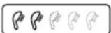
Hot water for 2 showers is ready to use. The third shower is in the process of heating. The final objective is to have hot water equivalent to 3 showers.
In the "Manual control" mode and the "BOOST" mode the screen visualizes a timer counting the estimate time remaining until the set amount of hot water is reached.
Problem log
| Code of error | Name of error |
| Er1 | Sensor 1 – The lower sensor is switched off |
| Er2 | Sensor 1 - The lower sensor is in short circuit |
| Er3 | Sensor 1 – The upper sensor is switched off |
| Er4 | Sensor 1 - The upper sensor is in short circuit |
| Er5 | Sensor 2 – The lower sensor is switched off |
| Er6 | Sensor 2 - The upper sensor is in short circuit |
| Er7 | Sensor 2 – The lower sensor is switched off |
| Er8 | Sensor 2 - The upper sensor is in short circuit |
| Er9 Software error | |
| Er10 The water heater is turned on without any water present (H1) | |
| Er11 The water heater is turned on without any water present (H2) | |
Note: If you see the symbol and any of the above listed errors, please contact an authorized service centre. You can find a list of them in the warranty card.
VII. PERIODIC MAINTENANCE
In the conditions of normal use of the water heater, under the influence of high temperature, limestone (the so-called lime scale) deposits on the surface of the heating element. This worsens the heat exchange between the heating element and the water. The temperature on the surface of the heating element and around it increases. Specific noise can be heard – of boiling water. The thermoregulator begins to switch on and off more frequently. A "deceptive" activation of the thermal protection is possible. Due to these facts, the manufacturer recommends preventive maintenance of your water heater every two years by an authorized service centre or service facility, this service remaining at the customer's expense. This preventive maintenance should include cleaning and examination of the anode protector (for water heaters with glass-ceramic coating), which has to be replaced with a new one, if necessary.
To clean the appliance, use a damp cloth. Do not use abrasive or solvent-containing detergents.
The manufacturer does not bear responsibility for any consequences arising from non-adherence to these instructions.
Instructions for protection of the environment
Old electric appliances contain valuable materials and must not be disposed of with the domestic waste! Please contribute actively for the protection of the resources and the environment and dispose of the appliance in the buy-back centres organized for this purpose (if such are available).
•Das Symbol "Duschkopf"
Vysvetlivka k fig.6:
T1, T2 – termovypínač; TR/EC – termoregulátor/ elektronický blok; S1, S2 – snímač; R1, R2 – ohrievač; F1, F2 – príruba; Wi-Fi (ak ide oWi-Fi).
V. PROTIKORÓZNA OCHRANA - HORČÍKOVÁ ANÓDA
2. Raccordement hydraulique
Explication figure 6:
WARNING: The electrical power supply of the device should be switched on. The safety valve and the pipe connecting it to the device must be secured against g.
- Modus "Weekprogramma"
text_image
1 2 3 4 5 6 7 8 9 ← ↕ ↙ ↗ ↙ ↙ ↙ ↙ ↙ ↙ ↙ ↙ ↙ ↙ ↙ ↙ ↙ ↙ ↙ ↙ ↙ ↙ ↙ ↙ ↙ ↙ ↙ ↙ ↙ ↙ ↙ ↙ ↙ ↙ ↙ ↙ ↙ ↙ ↙ ↙ ↙ ↙ ↙ ↙ ↙ ↙ ↙ ↙ ↙ ↙ ↙ ↙ ↙ ↙ ↘natural_image
Line drawing of a drill bit being inserted into a grid-patterned panel, with no text or symbols present.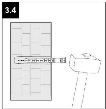
natural_image
Technical line drawing of a mechanical assembly with a bracket and pin, no text or symbols present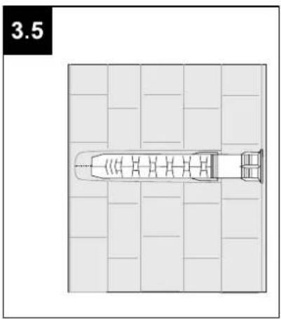
natural_image
Top-down architectural plan of a boat on a grid layout (no text or symbols)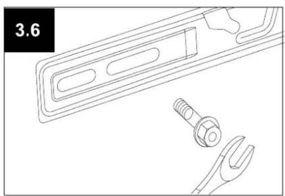
natural_image
Technical line drawing of a mechanical component with a wrench, pliers, and a bracket (no text or symbols)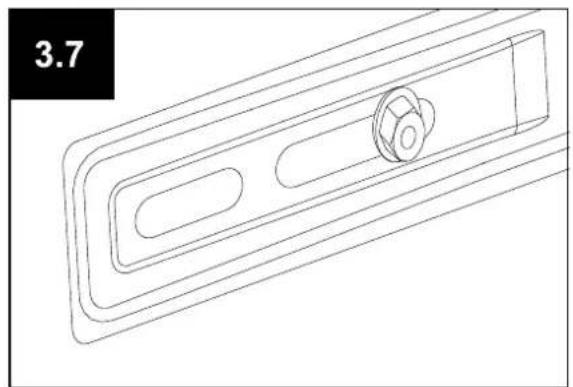
natural_image
Technical line drawing of a mechanical component with a central knob (no text or symbols)
natural_image
Black triangular warning symbol with exclamation mark (no text or numbers)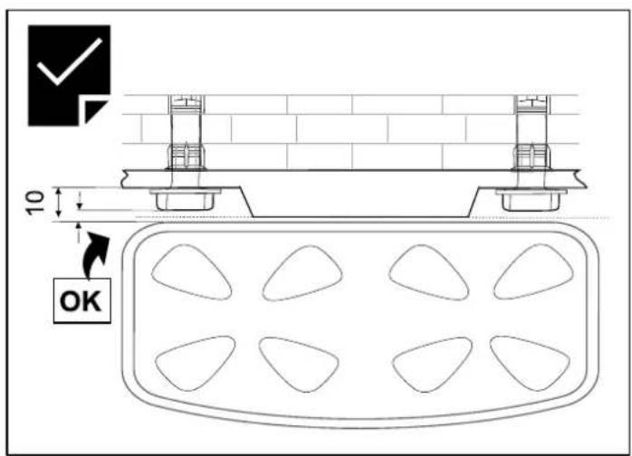
text_image
10 OK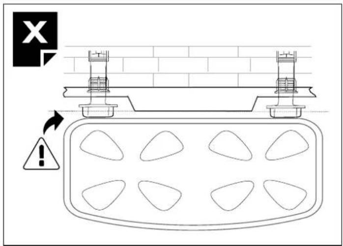
text_image
Technical diagram showing a structural assembly with warning sign and warning triangle, including a warning symbol and X icon.4.1
text_image
Technical diagram showing assembly steps of a device with labeled components and directional arrows indicating motion.4.2
text_image
Technical diagram showing installation of a door panel with labeled components and warning symbol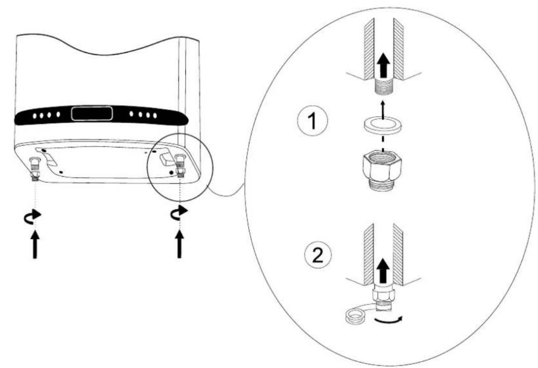
text_image
Diagram showing air conditioner installation steps with numbered instructions for assembly or repair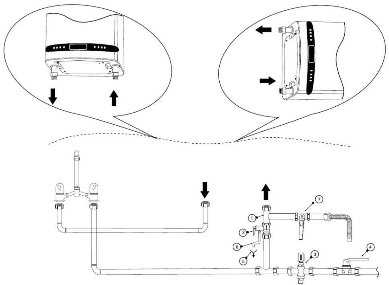
text_image
Technical diagram showing pipe installation and component assembly with numbered parts and directional arrows indicating flow or movement.6.1
Electrical diagrams - Copper heating element
* Wi-Fi module - optional
flowchart
graph TD
    subgraph Power module
        A["Sensor 1"] --> B["L(4) OUT(3) REL 1"]
        C["Sensor 2"] --> D["L(4) OUT(3) REL 2"]
        B --> E["TR / EC"]
        D --> E
    end
    F1 --> G["F1"]
    F2 --> H["F2"]
    I1 --> I1
    I2 --> I2
    I3 --> I3
    I4 --> I4
    I5 --> I5
    I6 --> I6
    I7 --> I7
    I8 --> I8
    I9 --> I9
    I10 --> I10
    I11 --> I11
    I12 --> I12
    I13 --> I13
    I14 --> I14
    I15 --> I15
    I16 --> I16
    I17 --> I17
    I18 --> I18
    I19 --> I19
    I20 --> I20
    style Wi-Fi module fill:#f9f,stroke:#333,stroke-width:2px
text_image
Brown T2 A1 / L Blue B1 / N yellow/green flange6.2
Electrical diagrams - DRY heating element
*Wi-FI module - optional
text_image
Brown T2 A1 / L Blue B1 / N yellow/green flange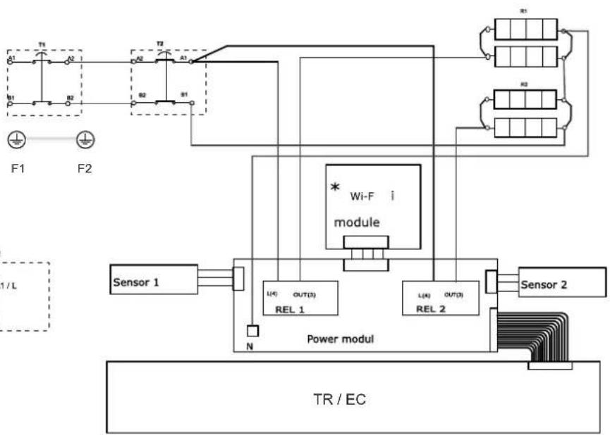
flowchart
graph TD
    subgraph_Power_modul["Power modul"]
        A1["Sensor 1"] --> B1["REL 1"]
        A2["Sensor 2"] --> B2["REL 2"]
        B1 --> C1["Wi-Fi module"]
        B2 --> C2["Wi-Fi module"]
        C1 --> D1["TR/EC"]
        C2 --> D2["TR/EC"]
    end
    subgraph_Control["Control Panel"]
        E1["T1"] --> F1["F1"]
        E2["T2"] --> F2["F2"]
        E3["T3"] --> F3["F3"]
        E4["T4"] --> F4["F4"]
        E5["T5"] --> F5["F5"]
        E6["T6"] --> F6["F6"]
        E7["T7"] --> F7["F7"]
        E8["T8"] --> F8["F8"]
        E9["T9"] --> F9["F9"]
        E10["T10"] --> F10["F10"]
    end
    style Power_modul fill:#f9f,stroke:#333
    style Control fill:#ccf,stroke:#333
6.3
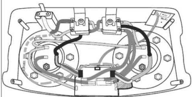
Electrical diagrams - Copper heating element
*Wi-FI module - optional
natural_image
Technical diagram of a vehicle's internal wiring and components (no text or labels)6.4
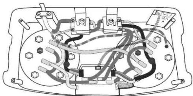
Electrical diagrams - DRY heating element
*Wi-FI module - optional
natural_image
Technical diagram of an electrical or mechanical component with visible wiring and mounting points (no text or symbols)7
text_image
7.1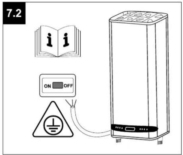
text_image
7.2 ON OFF7.3
text_image
Diagram showing an open book with 'i i' and a warning sign with 'ON OFF' pointing to a battery.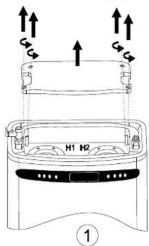
text_image
H1 H2 ①
text_image
H1 H2 ②8
text_image
Diagram showing a hand pressing a button next to icons for weather, phone status, and smart home controls with time and WiFi labels.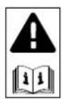
flowchart
graph TD
    A["Vertical position"] --> B["28:00"]
    B --> C["28:00"]
    C --> D["Horizontal position"]
    D --> E["Press 5s "in Stand By" Mode"]
    style A fill:#f9f,stroke:#333
    style B fill:#ccf,stroke:#333
    style C fill:#cfc,stroke:#333
    style D fill:#fcc,stroke:#333
    style E fill:#ffc,stroke:#333
text_image
TESY Default Settings: WiFi AP: TCH XXXXXX IP: http:// 10.0.0.1 H1 H27
TESY
TESY Ltd
Shumen, 9700, 48 Blvd. Madara,
PHONE: +359 54 859 129,
office@tesy.com
ТЕСИ ООД
9701 гр. Шумен, бул. Мадара 48,
PHONE: +359 54 859 129,
office@tesy.com