Pro - Guitar amp FENDER - Free user manual and instructions
Find the device manual for free Pro FENDER in PDF.
| Product Type | Tube Guitar Amplifier |
| Brand | Fender |
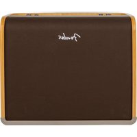
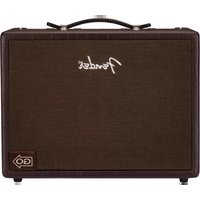
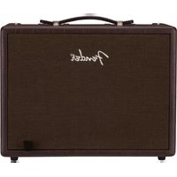
| Model | Pro (Pro Reverb / Concert Reverb) |
| Dimensions (Pro Reverb) | Height: 44.3 cm, Width: 64.7 cm, Depth: 32.8 cm |
| Weight (Pro Reverb) | 34 kg (75 lb) |
| Power Supply | 325 W, depending on version: 120V/60Hz, 230V/50Hz, 240V/50Hz, 100V/50-60Hz |
| Output Power | 50 W RMS (full power) / 12.5 W RMS (1/4 power) |
| Tubes | 2 x 6L6GC, 2 x 12AX7A, 5 x 12AX7WA, 1 x 12AX7A |
| Speakers | Pro Reverb: 1 x 12" Jensen 8 ohms; Concert Reverb: 4 x 10" Fender 8 ohms |
| Included Footswitch | 4 buttons: Channel, Effects Loop, Reverb, Tremolo |
| Main Features | Two channels, spring reverb, tremolo, effects loop, preamp out, power amp in, power selector |
| Maintenance and Cleaning | Unplug the power cord before cleaning; wait for the device to be completely dry before reconnecting |
| Safety | Grounding required; do not expose to moisture or rain; maintenance by qualified personnel only |
| Repairability | Bias and balance adjustment for power tubes; tube replacement (6L6GC, 12AX7); fuses F200, F1, F2 |
| General Information | Construction with birch/maple plywood, Tolex covering; adjustable rear supports |
Frequently Asked Questions - Pro FENDER
User questions about Pro FENDER
0 question about this device. Answer the ones you know or ask your own.
Ask a new question about this device
Download the instructions for your Guitar amp in PDF format for free! Find your manual Pro - FENDER and take your electronic device back in hand. On this page are published all the documents necessary for the use of your device. Pro by FENDER.
USER MANUAL Pro FENDER
Fender amplifiers and loudspeaker systems are capable of producing very high sound pressure levels which may cause temporary or permanent hearing damage. Use care when setting and adjusting volume levels during use.
- Maintain at least 6 inches of unobstructed air space behind the unit to allow for proper ventilation and cooling.


This symbol warns the user of dangerous voltage levels localized within the enclosure.
This symbol advises the user to read all accompanying literature for safe operation of the unit.
ESPANOL - PAGINAS 8-11
To prevent damage, fire or shock hazard, do not expose this unit to rain or moisture.
No user serviceable parts inside, refer servicing to qualified personnel only.
- Do not alter the AC plug.
This unit must be earth grounded.
Unplug the AC power line cord before cleaning the unit's exterior (use a damp cloth only). Wait until the unit is completely dry before reconnecting it to power.
WARNING: Exercise caution when servicing this unit. This unit is not completely disconnected from the power source when the power switch is in the OFF position and the power indicator is not lit. In some applications, the power cord is not polarized and the 'hot' and 'neutral' lines may be reversed in use. Consult qualified service personnel.
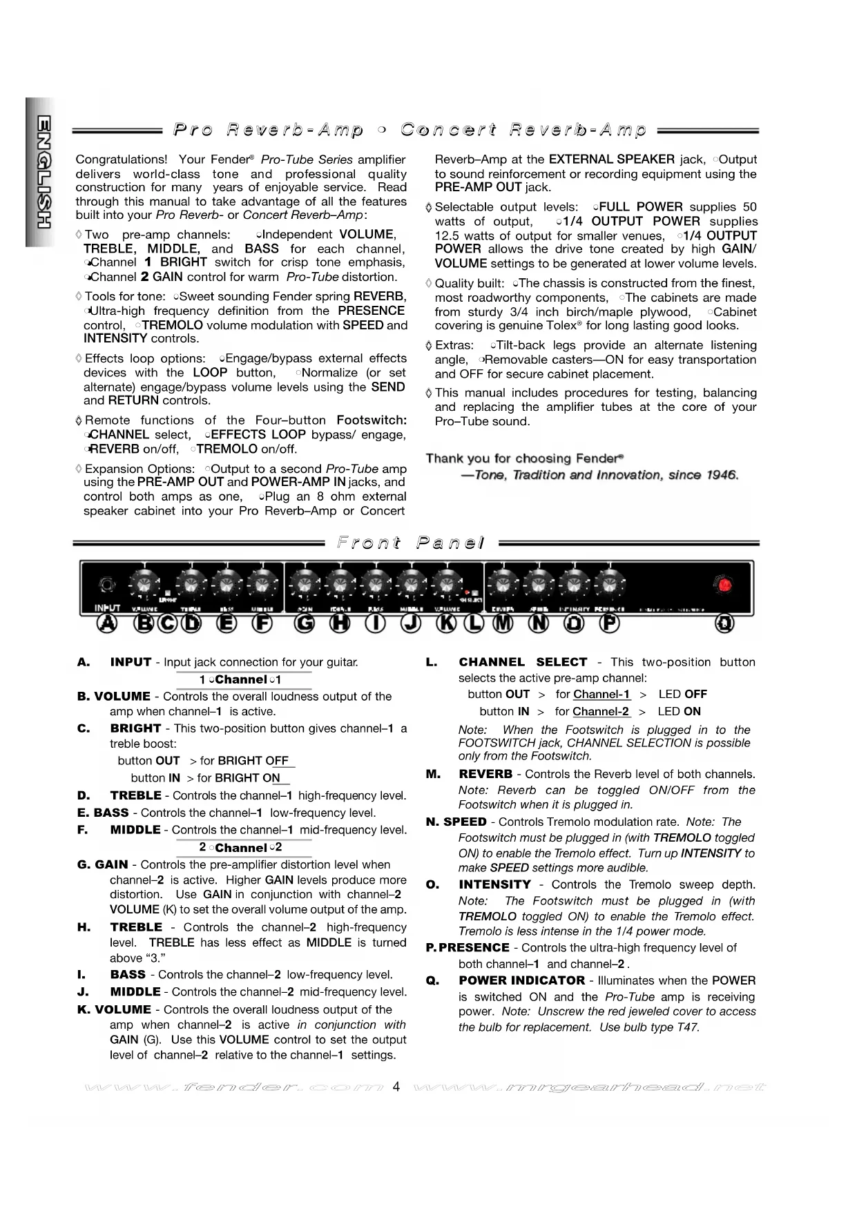
Congratulations! Your Fender® Pro-Tube Series amplifier delivers world-class tone and professional quality construction for many years of enjoyable service. Read through this manual to take advantage of all the features built into your Pro Reverb- or Concert Reverb-Amp:
Two pre-amp channels: Independent VOLUME, TREBLE, MIDDLE, and BASS for each channel, Channel 1 BRIGHT switch for crisp tone emphasis, Channel 2 GAIN control for warm Pro-Tube distortion.
Tools for tone: Sweet sounding Fender spring REVERB, Ultra-high frequency definition from the PRESENCE control, TREMOLO volume modulation with SPEED and INTENSITY controls.
Effects loop options: Engage/bypass external effects devices with the LOOP button, Normalize (or set alternate) engage/bypass volume levels using the SEND and RETURN controls.
Remote functions of the Four-button Footswitch: CHANNEL select, EFFECTS LOOP bypass/ engage, REVERB on/off, TREMOLO on/off.
Expansion Options: Output to a second Pro-Tube amp using the PRE-AMP OUT and POWER-AMP IN jacks, and control both amps as one, Plug an 8 ohm external speaker cabinet into your Pro Reverb-Amp or Concert
Reverb-Amp at the EXTERNAL SPEAKER jack, Output to sound reinforcement or recording equipment using the PRE-AMP OUT jack.
Selectable output levels: FULL POWER supplies 50 watts of output, 1/4 OUTPUT POWER supplies 12.5 watts of output for smaller venues, 1/4 OUTPUT POWER allows the drive tone created by high GAIN/VOLUME settings to be generated at lower volume levels.
Quality built: The chassis is constructed from the finest, most roadworthy components, The cabinets are made from sturdy 3/4 inch birch/maple plywood, Cabinet covering is genuine Tolex for long lasting good looks.
Extras: ^ 念 Tilt-back legs provide an alternate listening angle, Removable casters-ON for easy transportation and OFF for secure cabinet placement.
This manual includes procedures for testing, balancing and replacing the amplifier tubes at the core of your Pro-Tube sound.
Thank you for choosing Fender®
—Tone, Tradition and Innovation, since 1946.
Front Panel
$$ \begin{array}{l} \text {b u t t o n O U T > f o r B R I G H T O F F} \ \text {b u t t o n I N > f o r B R I G H T O N} \end{array} $$
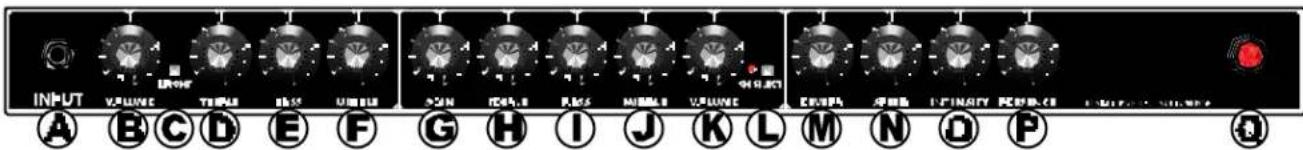
A. INPUT - Input jack connection for your guitar. 1Channel
B. VOLUME - Controls the overall loudness output of the amp when channel-1 is active.
C. BRIGHT - This two-position button gives channel-1 a treble boost:
D. TREBLE - Controls the channel-1 high-frequency level.
E. BASS - Controls the channel-1 low-frequency level.
F. MIDDLE - Controls the channel-1 mid-frequency level. 2 Channel 2
G. GAIN - Controls the pre-amplifier distortion level when channel-2 is active. Higher GAIN levels produce more distortion. Use GAIN in conjunction with channel-2 VOLUME (K) to set the overall volume output of the amp.
H. TREBLE - Controls the channel-2 high-frequency level. TREBLE has less effect as MIDDLE is turned above "3."
I. BASS - Controls the channel-2 low-frequency level.
J. MIDDLE - Controls the channel-2 mid-frequency level.
K. VOLUME - Controls the overall loudness output of the amp when channel-2 is active in conjunction with GAIN (G). Use this VOLUME control to set the output level of channel-2 relative to the channel-1 settings.
L. CHANNEL SELECT - This two-position button selects the active pre-amp channel:
$$ \begin{array}{l} \text {b u t t o n O U T > f o r C h a n n e l - 1 > L E D O F F} \ \text {b u t t o n I N > f o r C h a n n e l - 2 > L E D O N} \end{array} $$
Note: When the Footswitch is plugged in to the FOOTSWITCH jack, CHANNEL SELECTION is possible only from the Footswitch.
M. REVERB - Controls the Reverb level of both channels. Note: Reverb can be toggled ON/OFF from the Footswitch when it is plugged in.
N. SPEED - Controls Tremolo modulation rate. Note: The Footswitch must be plugged in (with TREMOLO toggled ON) to enable the Tremolo effect. Turn up INTENSITY to make SPEED settings more audible.
O. INTENSITY - Controls the Tremolo sweep depth. Note: The Footswitch must be plugged in (with TREMOLO toggled ON) to enable the Tremolo effect. Tremolo is less intense in the 1/4 power mode.
P. PRESENCE - Controls the ultra-high frequency level of both channel-1 and channel-2.
Q. POWER INDICATOR - Illuminates when the POWER is switched ON and the Pro-Tube amp is receiving power. Note: Unscrew the red jeweled cover to access the bulb for replacement. Use bulb type T47.
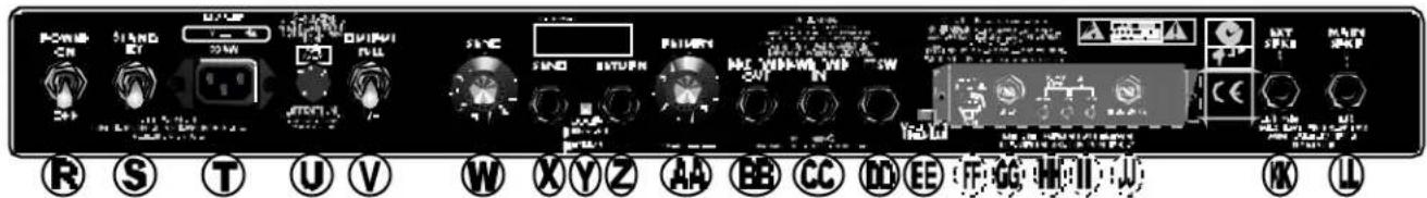
R. POWER - Switches power ON and OFF to the amplifier. (Reduce the "shock" to amplifier tubes at power-up, extending their life span, by turning the amp ON with the STAND BY switch DOWN for the first minute, then UP for normal use.
S. STAND BY - In the DOWN position, this switch puts the amp on stand by. Audio is muted and power is supplied only to the tube filaments. Use STAND BY in place of switching POWER OFF during short breaks (one hour max.). This eliminates the normal warm-up time when STAND BY is switched OFF (UP) when returning to play the amplifier and also extends the life span of your amplifier's tubes.
T. IEC LINE CORD CONNECTOR - Connect the supplied IEC POWER LINE CORD to a grounded AC receptacle in accordance with the voltage and frequency ratings as shown on the rear panel of the amplifier.
U. FUSE - Power Mains fuse, protects the amplifier from electrical faults. Replace a failed fuse only with the proper type and rating (See FUSE F200 under "Specifications"). If a fuse repeatedly fails, consult an authorized Fender service technician.
V. OUTPUT POWER - Selects amplifier output power: ∅FULL (50 watts), or ∅1/4 (12.5 watts).
Note: See "Effects Loop Settings" on the next page for details on the use of items (W-AA).
W. SEND - Controls the SEND jack output level.
X. SEND JACK - Output jack for connection to the input jack of effects devices in an effects loop.
Y. LOOP - This two position button engages/bypasses the effects loop:
button OUT > to BYPASS the effects loop button IN > to ENGAGE the effects loop
*Note: When the Footswitch is plugged into the FOOTSWITCH jack, effects LOOP BYPASS/ENGAGE are possible only from the Footswitch.
Z. RETURN JACK - Input jack for connection to the output jack of an effects device in an effects loop.
AA. RETURN - Controls the RETURN jack input level going into the power amp.
BB. PRE AMP OUT JACK - This output jack supplies an unbalanced, line-level signal (with Reverb) to a recording/sound reinforcement console, or to an external power amplifier such as another Pro-Tube amplifier used as an extension amp.
CC. POWER AMP IN - This input jack connects directly to the power amplifier, automatically disconnecting the preamp signal from the circuit. When using your Pro-Tube as an extension amp, connect the PRE-AMP OUT jack on another Pro-Tube amp, to this jack. Control both units from the source amplifier.
DD. FOOTSWITCH JACK - Connect the supplied 4-button Footswitch at this jack to enable these Footswitching functions:
SELECT Pre-Amp Channel
BYPASS/ENGAGE the Effects Loop
Switch Tremolo ON/OFF
SwitchReverbON/OFF
*Note: When the Footswitch is plugged into the FOOTSWITCH jack, CHANNEL SELECTION and effects LOOP BYPASS/ENGAGE are possible only from the Footswitch.
EE.JJ. (See "Tube Adjustment" on the next page.)
KK. EXTERNAL SPEAKER JACK - Connect an 8 ohm external speaker cabinet at this jack only if another 8 ohm speaker load is connected at the MAIN SPEAKER jack (see MAIN SPEAKER jack and "Speaker Connection Guide" below).
Note: When a plug is inserted in the EXTERNAL SPEAKER jack, the amplifier is automatically switched to handle a 4 ohm speaker load.
LL. MAIN SPEAKER JACK - Keep the internal speakers connected at this jack for normal amplifier operation (8 ohm load).
IMPORTANT: SPEAKERS MUST ALWAYS BE CONNECTED AT THE MAIN SPEAKER JACK WHEN THE AMPLIFIER IS SWITCHED ON TO PREVENT SERIOUS DAMAGE TO THE AMPLIFIER!
Speaker Connection Guide
Connect speakers to MAIN SPKR and EXT SPKR jacks using these configurations:
| MAIN SPEAKERJACK | EXTERNAL SPEAKERJACK | PROPER LOAD | |
| Internal 8 ohm | + | NONE | = 8 ohms |
| External 8 ohm | + | NONE | = 8 ohms |
| Internal 8 ohm | + | External 8 ohm | = 4 ohms2 |
| External 8 ohm | + | External 8 ohm | = 4 ohms2 |
ALWAYS Keep a Speaker Connected to the MAIN SPKR Jack When the Amp is ON!
Note: When a plug is inserted in the EXTERNAL SPEAKER jack, the amplifier is automatically switched to handle a 4 ohm speaker load.
BYPASS and ENGAGE Volume Levels
Use the SEND and RETURN level controls to normalize (make equal) the ENGAGE and BYPASS volume levels. Or, set the two levels unequal to create a preset alternate volume level, selectable from the Footswitch. Note: The alternate volume level will function with or without effects devices plugged into the loop jacks.
Setting effects loop levels.
Turn SEND and RETURN knobs down to "1."
- BYPASS the effects loop from the rear panel or the Footswitch.
- Connect effects device(s) to the rear panel SEND and RETURN jacks (optional for alternate volume level setting).
- Play guitar and set the amp and instrument levels as preferred. This is your bypass level.
- ENGAGE the effects loop.
While playing guitar, turn SEND and RETURN up together* to match the bypass level set above (or to any alternate volume level). This is your engage level.
- By quickly switching between BYPASS and ENGAGE while playing, you can fine tune these settings.
*Hear unwanted distortion? Turning SEND and RETURN up at the same rate is usually a good way of setting levels quickly that will work with an external effects device. But with multiple effects devices or with devices having their own level controls, unwanted distortion may develop. Try reducing the SEND level or the level controls on individual effects devices, (increasing RETURN or MASTER will restore the overall volume level). Listen for improvement after each change. Experiment to find the right settings.
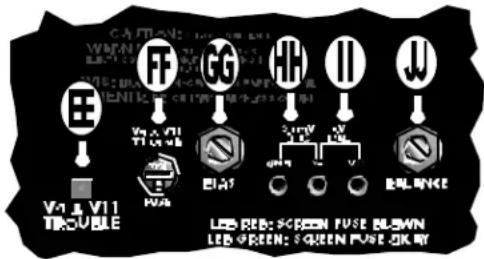
Tube Adjustment
EE. V9 & V11 TROUBLE LED - Functional only with the STAND BY switch in the UP position. This LED glows red when either the V9 or V11 tube has failed.
FF. FUSE V9 & V11 (F1) - Protects the amplifier from damage if the V9 or V11 tube were to fail. If this fuse fails, replace the tubes in locations V9 & V11, this fuse, then set the BIAS and BALANCE.
GG. BIAS ADJUSTMENT - Trim adjustment used in conjunction with BIAS test points to set the proper tube BIAS.
HH. BIAS TEST POINTS - Test points used to measure output tube BIAS.
II. BALANCE TEST POINTS - Test points used to measure the BALANCE between power tube sections.
JJ. BALANCE ADJUSTMENT - Trim adjustment used in conjunction with the BALANCE test points to set the proper tube BALANCE.
The TROUBLE LEDs do not indicate tube wear. Tubes may be "worn" and sound weak even when the TROUBLE LED still glows green. DO NOT WAIT FOR TUBE FAILURE TO REPLACE TUBES, (see "Tube Replacement" on the next page).
Only replace a failed fuse with the proper type as indicated under "Specifications" on the next page. The fuse item F1 is used for tube failure protection. If a fuse repeatedly fails, consult with an authorized Fender service technician.
Visit Fender online at:
ww . w . f e n d e r . c o mww . w . m . g e a r h e a d . n e t
OUTPUT TUBE BIAS & BALANCE ADJUSTMENTS.
- Warm up the Pro-Tube amp for 2 minutes with STAND BY switch DOWN and OUTPUT POWER set to FULL. Set SPEED and INTENSITY to "1" and toggle TREMOLO OFF. Put the STAND BY switch in the UP position.
- Remove the bias controls cover box.
- Set BIAS: With a DC voltmeter measure VDC between "GND" and "V9" test points while adjusting BIAS for .03 VDC (30mVDC).
- Set BALANCE: Measure the VDC between the "V9" and "V11" test points while adjusting BALANCE for zero (0) VDC.
- Replace the bias controls cover box.
IMPORTANT
- Make BIAS and BALANCE adjustments only when necessary. Take your Pro-Tube amp to the nearest authorized Fender Service Center if you are not sure about the settings.
- Always set BIAS first, then BALANCE.
- If the output tubes (6L6GC's) cannot be BALANCED, replace the output tubes (V9 & V11), then set BIAS and BALANCE.
FENRESPACIOVSGVPCETNCTUPOPRIVEMETMUR PRRERMAENTNTTNSIMINTRST2SUS HEPPLCNPNTNFRNGNAQUEMENTNTPSONY
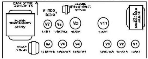
FIG.A
Tube life span depends upon things such as amplifier load and playing style. Power amplifier output tubes have a shorter life span than pre-amplifier tubes and usually need attention first. A simple way to check if your tubes are noticeably worn, is to replace them with a spare new set and listen for any improvement in tone quality:
ALWAYS unplug the amplifier when replacing tubes. Replace tubes ONLY with the proper type (see "Specifications" below).
CAUTION: let tubes cool before handling, they get HOT...
- Replace the OUTPUT tubes (V9, V11 in FIG. A) with a new set. Set BIAS and BALANCE. Listen for any improvement.
- Keep the new OUTPUT tubes in place. Replace the PREAMPLIFIER tubes (V1, V2, V3, V4, V5, V6, V7, V8 in FIG. A) with a new set. Listen for improvement.
- Keep the new PRE-AMPLIFIER tubes in place. Put the original OUTPUT tubes back in the amplifier. Set BIAS and BALANCE. Listen for any improvement.
If there is a noticeable improvement in sound quality after any of the 3 steps above, keep the tube arrangement that sounds the best. Obtain new spare tubes for future testing and tube replacement.
Specifications
MODEL / TYPE
Concert Reverb-Amp / PR 450
Pro Reverb-Amp / PR 448
PART NUMBER 021-5900-000 (120V, 60Hz) USA, 021-5500-000 (120V, 60Hz) USA
021-5960-000 (230V, 50Hz) Europe 021-5560-000 (230V, 50Hz) Europe
021-5940-000 (230V, 50Hz) UK 021-5540-000 (230V, 50Hz) UK
021-5930-000 (240V, 50Hz) Aust 021-5530-000 (240V, 50Hz) Aust
021-5970-000 (100V, 50/60Hz) Japan 021-5570-000 (100V, 50/60Hz) Japan
POWER REQUIREMENTS 325W 325W
POWER OUTPUT 50W RMS (Full Output)
50W RMS (Full Output)
12.5W RMS (1/4 Output)
12.5W RMS (1/4 Output)
1kHz sine into 8 ohms @ <5% THD, (Presence @ "1")
1kHz sine into 8 ohms @ <5% THD (Presence @ "1")
INPUT IMPEDANCE
1M ohm
1M ohm
TUBES
Two 6L6GC (P/N 053980)
Two 6L6GC (P/N 053980)
Two 12AX7A (P/N 023572)
Two 12AX7A (P/N 023572)
Five 12AX7WA (P/N 013341)
Five 12AX7WA (P/N 013341)
One 12AT7 (P/N 023531)
One 12AT7 (P/N 023531)
FUSES
F200: F3A 250V (110V, 120V units)
F3A 250V (110V, 120V units)
(Internal Filament Fuse)
T2A 250V (230V, 240V units)
T2A 250V (230V, 240V units)
F201: T5A 250V (230V, 240V units)
T5A 250V (230V, 240V units)
F1 & F2: T100mA (all units)
T100mA (all units)
SPEAKERS
Four Fender 10 in., 8 ohm, (P/N 048832)
One Jensen 12 in., 8 ohm, (P/N 057065)
FOOTSWITCH
Four-Button: Channel, Loop,
Four-Button: Channel, Loop,
Reverb, Tremolo (P/N 057025)
Reverb, Tremolo (P/N 057025)
DIMENSIONS
Height: 25 3/4 in.
(65.7 cm)
17 3/8 in.
(44.3 cm)
Width: 253/8 in.
(64.7 cm)
25 3/8 in.
(64.7 cm)
Depth: 12 27/32 in.
(32.8 cm)
12 27/32 in.
(32.8 cm)
85 lbs.
(38.6 kg)
75 lbs.
(34 kg)
Product specifications are subject to change without notice.
CONECTOR CONECTOR CARGA MAINSPEAKER EXTERNALSPEAKER TOTAL
Interno 8 ohmios + NINGUNO = 8 ohmios
Externo 8 ohmios + NINGUNO = 8 ohmios
Interno 8 ohmios + Externo 8 ohmios = 4 ohmios²
Externo 8 ohmios + Externo 8 ohmios = 4 ohmios²
FNNNNSNNSNNSNNSNNSNNSNNSNNSNNSNNSNNSNNSNNSNNSNNSNNSNNSNNSNNSNNSNNSNNSNNSNNSNNSNNSNNSNNSNNSNNSNNSNNSNNSNNSNNSNNSNNSNNSNNSNNSNNSNNSNNSNNSNNSNNSNNSNNSNNSNNSN
FIG.A

Interne 8 ohms + AUCUN = 8 ohms
External 8 ohms + AUCUN = 8 ohms
Interne 8ohms + Externe 8ohms = 4 ohms
Externe 8ohms + Externe 8ohms = 4ohms²
MAIN EXTERNAL GESAMT SPEAKER-BUCHSE SPEAKER-BUCHSE LAST
Intern 8 Ohm + KEIN = 8 Ohm
External 8 Ohm + KEIN = 8 Ohm
Intern 8 Ohm + Extern 8 Ohm = 4 Ohm²
External 8 Ohm + External 8 Ohm = 4 Ohm
www.fender.com www.mrgearhead.net