
WSP 300 H - Heating AEG - Free user manual and instructions
Find the device manual for free WSP 300 H AEG in PDF.
| Product type | Electric thermal storage heater for kitchen |
| Brand | AEG |
| Model | WSP 300 H |
| Storage capacity | 24 kWh |
| Charging power | 3.0 kW |
| Additional heating element (option) | 0.5 kW |
| Supply voltage | 3/N/PE ~400 V or 1/N/PE ~230 V |
| Dimensions (H x W x D) | 820 x 445/450 x 570/600 mm (height adjustable 815-840 mm) |
| Weight | Approximately 184 kg |
| Refractory bricks | 8 x SP28 |
| Main functions | Automatic heat storage, fan-assisted heat release, charge regulation, room thermostat |
| Regulation type | Electronic (charge and discharge) with room sensor and core sensor |
| Summer use | Charge and temperature buttons set to MIN |
| Safety | Temperature limiter, safety thermostats, safety switch |
| Maintenance and cleaning | Dust cleaning on fan and air mixing part by an installer; do not use detergent |
| Included accessories | Leveling plates, adjustable feet, protective caps |
| Optional accessories | Full cladding kit (front panel, top plate, side panels), additional heating element |
| Spare parts | Available on request with type and manufacturing number |
| Warranty | Manufacturer's warranty to be claimed in the country of purchase |
| Recycling | Packaging to be disposed of according to national regulations; appliance to be recycled at end of life |
Frequently Asked Questions - WSP 300 H AEG
User questions about WSP 300 H AEG
0 question about this device. Answer the ones you know or ask your own.
Ask a new question about this device
Download the instructions for your Heating in PDF format for free! Find your manual WSP 300 H - AEG and take your electronic device back in hand. On this page are published all the documents necessary for the use of your device. WSP 300 H by AEG.
USER MANUAL WSP 300 H AEG
Electric Storage Heaters
Kitchen Storage Heater
Operating and Installation instructions
WSP 300 H
Français
- Operating Instructions 22
1.1 Technical Description 22
1.2 Operation 22
1.2.1 Heat storage 22
1.2.2 Heat discharge 22
1.2.3 Summer operation 22
1.2.4 Energy saving tips 23
1.3 Important Instructions 23
1.4 Care and Maintenance 24
1.5 Important note 24
1.5.1 General 24
1.5.2 Defects 24
1.6 Trouble Shooting Tips 24
2.Installation instructions 26
2.1 Technical Data 26
2.2 Heater Positioning and Installation 26
2.2.1 Procedures to be followed 26
2.2.2 Choosing the Heater Position 26
2.2.3 Regulations governing heater position 26
2.2.4 Heater dimensions, fitting measurements 27
2.3 Assembly and Electrical Connection 28
2.3.1 Opening the heater 28
2.3.2 Adjusting the heater to working-top height 29
2.3.3 Running in the supply cables 30
2.3.4 Electrical connection 30
2.3.5 Circuit diagram WSP 300 H 31
2.3.6 Installation of heater core and elements 32
2.3.7 Installation of fan compartment and base board 33
2.3.8 Installation of kitchen unit front and adjusting boards 33
2.4 Rating Label 35
2.5 Spare parts 36
2.6 Accessories 36
2.6.1 Full decoration set 36
2.6.2 Day-acting Element 37
2.7 Commissioning the Heater 39
2.8 Re-assembly 39
3.Guarantee 39
3.1 Environment and recycling 39
François
Contenu
1. Operating Instructions
1.1 Technical Description
Storage heaters store electrically generated heat during low-cost electricity tariff periods (depending on the electricity supply company, mainly during the night hours). This is then discharged according to the desired room temperature as hot air by a fan.
1.2 Operation
The heater is operated using the recessable knobs on the top right of the heater. Pressing the knobs gently inwards causes them to spring outwards, further pressure causes them to recess back into the heater. The knobs can be recessed in any set position.
- Left hand knob = Charge control adjustment
- Right hand knob = Room thermostat adjustment
1.2.1 Heat storage
Heat storage takes place automatically. The residual heat left over from the previous day is always taken into account by the charge and discharge control during heater charging.
Automatic charge control
The heater charge adjusting knob should always be set at MAX (fully clockwise). If the charge should be reduced for any reason, this can be done by turning the knob slightly down. Any changes made to the settings will only be noticed on the following day. Do not, therefore, make too bigger changes to the settings.
The heat stored by the complete system is determined by the central charge control (in the distribution box). Please refer to the operating instructions which come with central charge control to adjust these settings.
Manual charging
If the heater is not connected to a central charge control, the amount of heat to be stored can be determined by the infinitely variable charge adjusting knob on the heater itself:
- no heat storage: fully anticlockwise
- full heat storage: fully clockwise
Once the set amount of heat has been stored, the heater switches off independently.
1.2.2 Heat discharge
The heat discharge is controlled by the charge and discharge control. If the room temperature sinks below the set temperature, the heater fan switches on and dissipates warm air into the room until the set temperature has been reached.
Day-acting element heater switch
This switch switches the day-acting element on and off. If no day-acting element is fitted, the switch has no function.
1.2.3 Summer operation
In the summer months, the operating knobs for charge and discharge and for the room temperature should be set to MIN (fully anticlockwise). Do not switch off the central charge control circuit breaker as this could cause the time clock in the central control to go out of synchronisation.
1.2.4 Energy saving tips
- Only heat when necessary.
- Keep the room temperature at 20^ if possible. Each degree above 20^ increases the heating costs by 6 to 7% . Likewise, each degree below 20^ saves the same amount of energy.
- Do not heat only by the radiation from the surfaces of the heater, but use the fan as well. If necessary, turn the heater charge adjusting knob slightly down (anti-clockwise).
- Use an automatic charge control to charge the heater if possible. Then, the heater will only store the amount of heat necessary to cover the heat load for the following day. A correctly adjusted charge control is a pre-requisite for an economic operation of the storage heater at comfortable room temperatures.
- During long periods of absence in the heating season allow the room temperature to sink, but not below 10^ . This saves energy without the risk of the building cooling out so far as to cause freezing of pipes, etc.
- Continuous airing of a building by having the windows ajar is too expensive. Short bursts of strong ventilation by opening windows fully is preferable. During ventilation, turn the room thermostat adjusting knob to MIN (fully anti-clockwise) so that the fan does not run.
- If windows and doors are draughty, improve the draught-excluding seals.
- Close blinds and shutters after dusk, reducing the loss of heat from the windows
- For reasons of fire safety, full-length curtains and blinds are not allowed in front of storage heaters. Apart from that, they reduce the heattransfer into the room, increase the losses via the windows and cause an increase in energy consumption.
- The building fabric (walls, ceilings, etc.) and also the furniture in the rooms absorb heat in a delayed time-frame, store this heat and transfer it back into the room very slowly. This should be taken into account when setting the room thermostat and also any night-time set back.
- Floors, ceilings and walls constitute a storage mass which was taken into account when sizing the heaters. If the night-time temperature set back is too drastic, this could lead to a lack of comfort during the day.
1.3 Important Instructions
- As the surfaces of the heater cabinet get hot in use, flammable or other objects presenting a danger of fire must not be placed on, or near the heater.
Do not, therefore, place any wooden objects, clothes or washing, newspapers, blankets or the like on or over the heater and do not put any pieces of furniture made of inflammable materials, nor spray tubes or similar objects closer than 25cm in front of, or on the heater, especially not in front of the air-outlet grille. - It is important to remember that the surfaces of the heater can reach temperatures in excess of 80^ during operation.
- The storage heater is only to be used in rooms where neither explosive gases (e.g. from floor-sealant), nor inflammable dust is present!
If renovation work causing dust accumulations is taking place the heaters must either be operated without the fans or switched off altogether.
- Electrical appliances conform to valid safety regulations. Repairs and service to electrical appliances must only be carried out by a competent electrician. Improper repair can mean distinct danger to the user
1.4 Care and Maintenance
- AFG heaters have been constructed so that they need only a minimum of maintenance.
- The fans are equipped with self-lubricating bearings. We recommend that the heater be opened from time to time by a qualified installer who can free the heater from any dust which may have accumulated on the fan or in the air-outlet channels.
- Cleaning and maintenance intervals are dependent on the conditions under which the heater works. We recommend that the first check take place at the latest before the beginning of the second heating period. Further maintenance intervals can then be individually set.
- We recommend that the control and regulation elements of the heater also be checked regularly. All safety, control and regulation elements should be checked by a qualified installer at the latest 10 years after initial installation. This can save unnecessary energy costs.
- Do not use soft-scrub or other abrasive substances to clean the surfaces of the heater. Normal household cleaners suffice entirely.
1.5 Important note
1.5.1 General
Please read this instruction carefully. It contains important information on safety, installation, use and maintenance of the heater.
The manufacturer cannot be held responsible for problems occurring when the following instructions are not adhered to. The appliance must only be used for the function intended.
This instruction leaflet must be:
- handed to the heater user after installation. The user is also to be instructed on the way this electric storage heater works.
- read carefully, retained for further use, and handed over to a new owner/user.
given to any maintenance engineer before repair work is carried out.
1.5.2 Defects
If the heater does not function correctly, please check the following points:
Is the heater charge control set to no-charge?
- Is the complete heating system switched off (via main switch)?
- Are the circuit breakers in the distribution box loose or defect?
If the heater cabinet is warm, but the fan is not running: Is the room thermostat working? Are the fuses for the fans in the distributor box loose or defect?
1.6 Trouble Shooting Tips
AEG Storage heaters are equipped with a continuous running charge and discharge control and a charge safety non-resetting limit switch. If the charge and discharge control does not switch off the elements under normal charging conditions, the non-resetting safety limit switches off the power supply to the elements. Problems in this category must only be repaired by a qualified installer (see Chapter "Important Instructions", 2.2.1).
If the heater does not work correctly, the following checks should be undertaken:
1. Heater does not store heat
- Check the circuit breakers and power switches in the control panel.
- Is there line voltage on the electronic charge control B1?
- Is there line voltage on the "SH" terminal of the electronic charge and discharge control B1?
Is the protective resistance R1 (22 Ohm) defective?
Is the thermal relay K1 switching correctly? Note: Switching delay of up to 2 minutes. -
Has the high-temperature safety cut-out F1 activated? The safety cut-out is reactivated by pressing the operating knob. Possible causes for high-temperature safety cut-out are:
-
defective charge thermostat
-
prohibited covering of the appliance causing overheating
-
Check the heating elements.
- Check the charge potentiometer (charge intensity regulator B5) (0 - 47kOhm)
- Check that the core temperature sensor B3 is sitting in the correct position and shows correct resistance values.
- Check the control voltage on terminals A1/Z1 and A2/Z2. The larger the control voltage, the less charge will be taken by the heater.
2. Heater always on full charge
- Does the charge and discharge regulator B1 switch off the thermal relay K1? Check the charge potentiometer (charge intensity regulator B5) and core temperature sensor B3.
Is the jumper bridge "max. charge" correctly positioned on the charge and discharge regulator? In slot IV. - Is the charge and discharge thermostat defective? If the heater is being charged by a charge control (central charge control), check the control voltage on terminals A1/Z1 - A2/Z2. If there is no measurable line voltage on the terminals, the charge control is possibly defective.
3. Appliance does not give out enough heat
- Chosen appliance is too small. Fan or room thermostat is defective. The charge control may possibly need to be adjusted to a higher value. Follow the special instructions in the corresponding charge control manual.
- Is the fan running? Check the room thermostat, fan safety cut-out F3 and if necessary the mechanics of the fan itself.
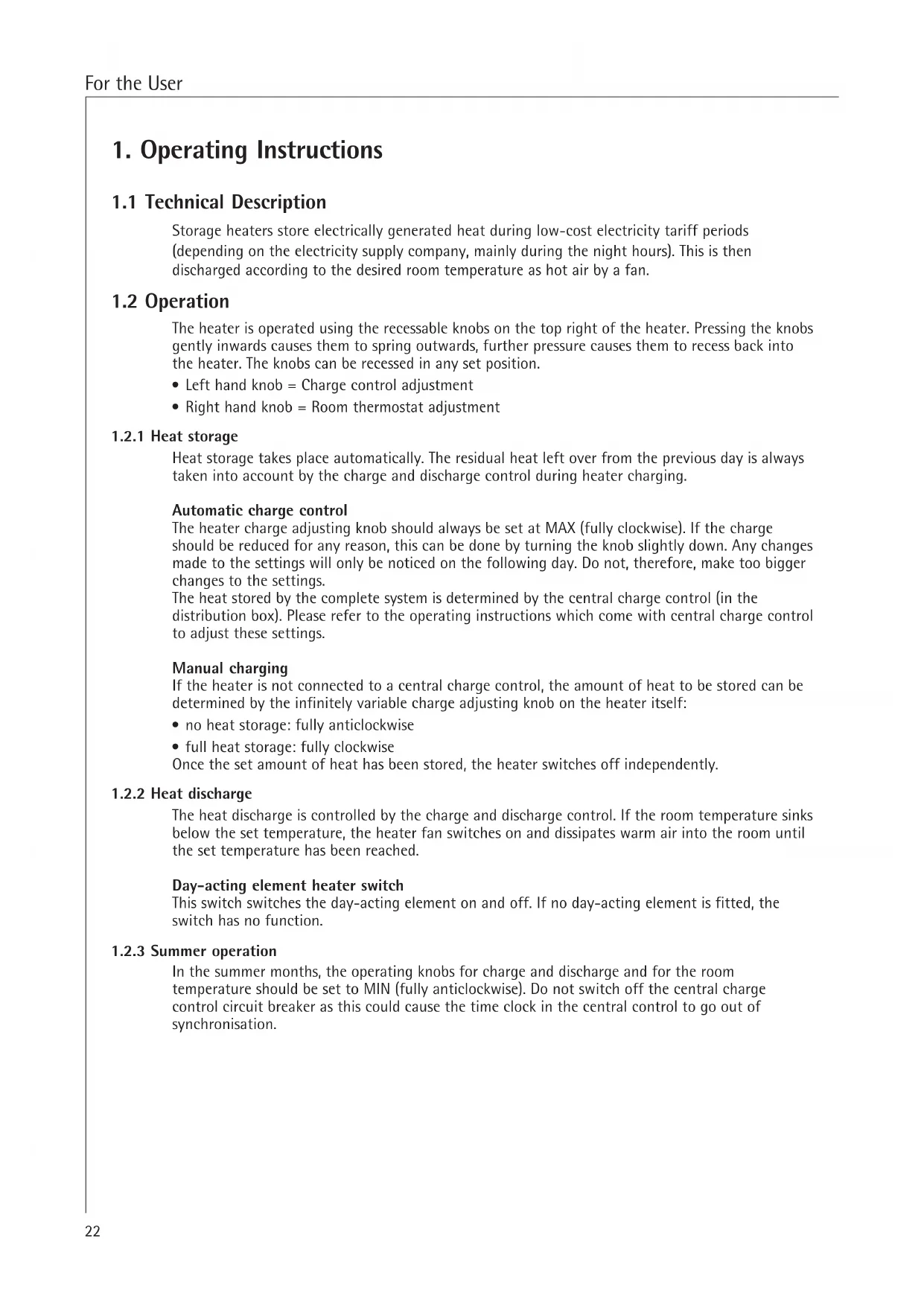
4. Characteristic curve of the core and room temperature sensors
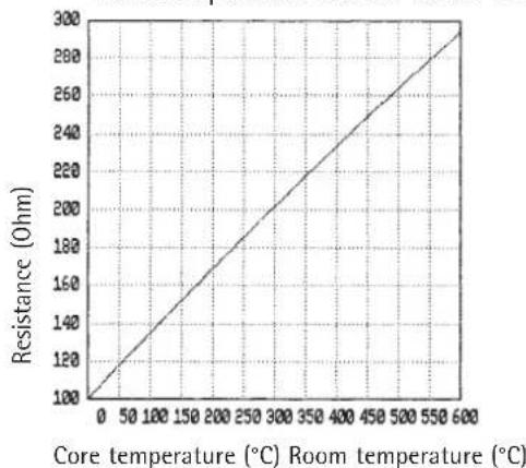
Core temperature sensor Room temperature sensor
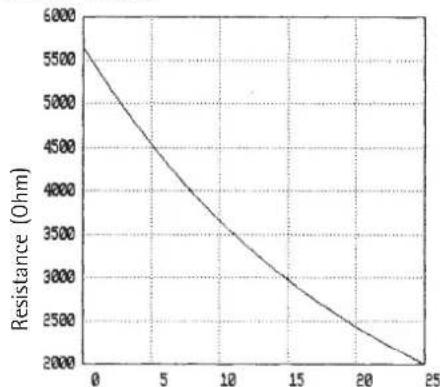
Fig. 1 Fig. 2
2. Installation instructions
2.1 Technical Data
| Model WSP 300 H | |
| Storage Capacity 24 kWh | |
| Rating 3.0 kW | |
| Voltage 3/N/PE ~ 400 V, 1/N/PE ~ 230 V | |
| Dimensions Height: 820 mm Width: 445 mm / 450 mm Depth: 570 | 1) / 850 mm 2) mm / 450 mm 2) mm / 600 mm 2) |
| Weight ca 184 kg | |
| Day-acting element 0.5 kW | |
| Core-brick packs 8 x SP28 |
1) adjustable from 815 - 840 mm
2) with working top
2.2 Heater Positioning and Installation
- The electrical installation of this heater must be approved by your local electricity company.
- The installation must be carried out by a competent electrician.
- Electrical installation and local safety regulations must also be adhered to.
- If heaters are to be installed in commercial or public buildings such as hotels, holiday homes or apartments, schools, administrative buildings etc., a special warning label is to be attached to the top of the heater. This label is available from your local contractor.
2.2.1 Procedures to be followed
All National and Local Safety Codes should be adhered to both at the planning and installation stages.
2.2.2 Choosing the Heater Position
The Kitchen Heater can either be integrated into any fitted kitchen unit or, using the special accessory set, be installed as a free-standing unit.
The floor must be able to take the weight of the heater. Please, therefore, note carefully the weight given in the Technical Data section (see section 2.1) of this instruction. If in doubt, consult a building engineer or architect.
AEG storage heaters generally need no protective underboard when standing on normal flooring, as long as this is flat and smooth and can withstand temperatures of 80^ minimum.
In the case of soft, load-sensitive or non-heat-resistant floors or carpeting, as well as to even out any surfaces, it is advisable to first put down a protective board the size of the underside of the heater. When using high- or thick-pile carpeting a protective board or floor-standing consoles should definitely be used.
2.2.3 Regulations governing heater position
Due to the low surface temperatures of the side panels, the storage heater can be positioned directly beside any other integrated appliance in a fitted kitchen.
It is not advisable, however, to place the heater next to a refrigerator or deep-freeze due to energy-saving considerations. The heater can be placed flush to the rear wall.
The warm air outlet and the cold air inlet must be keep free at all times. Any objects must be placed at least 30cm from the air grilles.
2.2.4 Heater dimensions, fitting measurements
The Kitchen Heater is designed to be built in below the working top. The heater's height is factory-set at 815 - 820mm .
Note: When measuring the height of the heater location recess, make sure that there is a minimum clearance of 8mm between the cover plate of the heater and the underside of the working top!
Dimensions of the heater location recess (nominal dimensions):
- Height: 825 mm
-Width:450mm - Depth: 570 mm (positioned flush to wall)
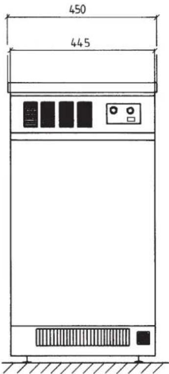
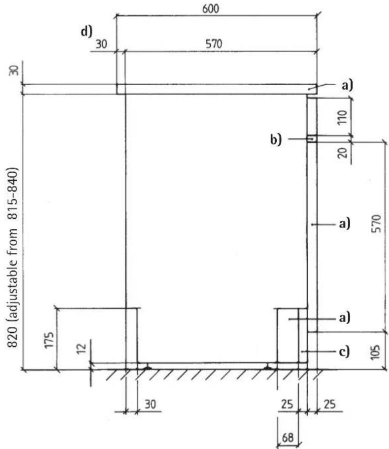
Fig. 3
a) Accessories
(cover plate, front panel, side fascia plates)
b) Factory supplied:
1 equalising fascia plate 10mm and 2 equalising fascia plates 20mm height supplied
c) Plinth cover plate 63mm continuously adjustable to rear of heater
d) Cover plate front or back, mountable with 30mm overhang
2.3 Assembly and Electrical Connection
The heater should be only removed from its packaging near to its place of final assembly. Small cracks or chips in the heater core bricks have no influence on the operation of the heater.
2.3.1 Opening the heater
- Take out the 2 fixing screws at the top right and left of the operating plate.
- Take out the 4 fixing screws on the front cover panel and remove the cover panel forwards. Remove the equalising fascia plates on the rear of the cover panel.
- Push the operating panel upwards, then outwards and remove it sideways.
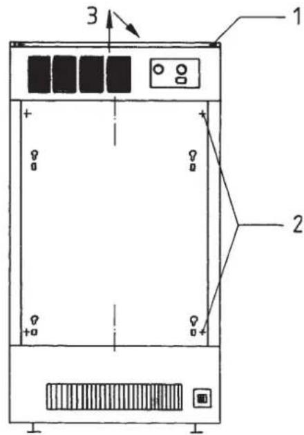
Fig. 4
- Take out the 2 fan compartment fixing screws at the bottom of the inside panel.
Remove the fan wiring from terminals 12 and N, and earth on the connecting panel.
Remove the connecting wires of the room temperature sensor B2 from the charge and discharge control B1 (bottom right, near the fan compartment) (take off the cable with 2 flat spade connectors 2.8 - TF1 and TF2).
Unscrew the thermostat F4 from the inside panel.
If a day acting element (DAE) is installed, remove the switching thermostat F2.1 from the inside panel and take off the DAE connecting wires from the control panel (remove wires to LH, N and earth).
Pull out the fan compartment together with the base board from the front of the heater.
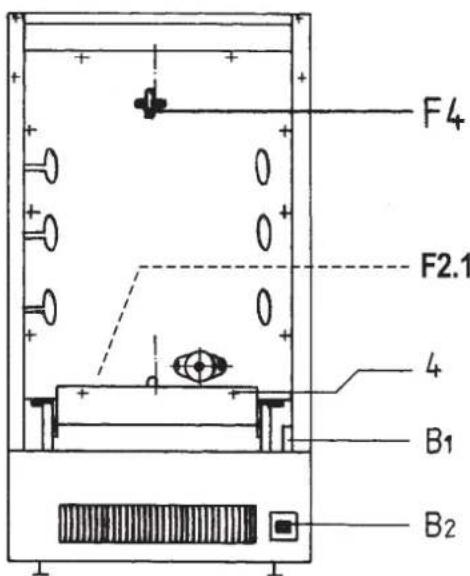
Fig. 5
Note: Make sure that no connecting wires are damaged, removed or taken out of the heater. Run the wires accordingly, so that this does not happen.
- Remove the safety cut-out thermostat F1 from the lower right hand side of the inside panel.
Remove the 8 inside panel fixing screws.
Remove the inside panel: to do this, pull the panel forwards on the right hand side and then remove it obliquely to the right.
Note: The insulation is fixed to the inside panel, handle with care!
- Remove the front insulation, the pack of fittings, heating elements, core cover plate and packaging materials from the core area.
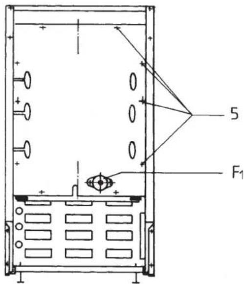
Fig. 6
2.3.2 Adjusting the heater to working-top height
Before the heater can be pushed under the working top, it must be adjusted to the correct height. To do this, place the heater on to the 4 plastic protection caps provided. The heater can then be continuously adjusted from 815 to 840mm using the adjustable feet.
To adjust the feet, loosen the counterscrews M10 on the inside of the heater (SW17 spanner). The height is then adjusted from the outside on the round base feet using an SW13 spanner or from inside the heater using the slot in the end of the winding. Use the steel plate end provided, or any other suitable tool to accomplish this. Retighten the counterscrews.
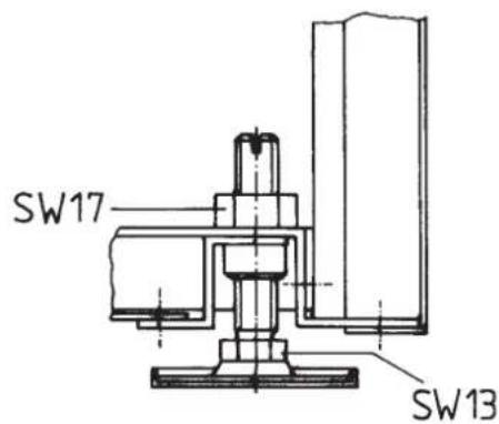
Fig. 7
Note: Using the heater adjustment from inside the appliance, a height adjustment can be made after the heater has been placed in its final position under the working top.
Note: In order to fix or remove the operating panel from the heater when it is position under the working top, a minimum clearance of 8mm must be allowed between the heater cover plate and the bottom of the working top!
2.3.3 Running in the supply cables
When integrating the heater into a built-in kitchen, measure off enough length of low-voltage, high-voltage and charge control supply cable to allow the heater to be electrically connected before integrating it below the working top. It is then possible to pull the heater out of its recess at a later date, for instance for repair work, without having to disconnect the supply cables. Before sliding the heater into its recess, bring in the supply cables from the rear of the heater through the cable feed on the lower left hand side of the rear panel and through the cable ties on the inner left side of the heater into the connecting compartment. Run the cables through the strain relief below the switching panel and clamp them tight. Pull the cable ties on the left side of the heater tight.
Caution: Make sure that the connecting cables run flush to the heater's left side and cannot touch the fan compartment. Hot surfaces!
When sliding the heater into its recess, make sure that the connecting cables are not unduly bent or pinched. The connecting cables must be run so that they have free movement behind the plinth recess.
2.3.4 Electrical connection
The storage heater appliance is connected to a load current (OFF-PEAK tariff) and control cables for the room thermostat and for the charge control (A1/Z1; A2/Z2). The cables A1/Z1 and A2/Z2 are at line-voltage 230V and may thus be run together with a L/N/PE cable for the room thermostat. The heater is suitable for direct connection without a spur, or with a wall socket.

According to regulations every branch circuit must be individually protected, for instance by circuit breakers for all phases. These circuit breakers must have contact openings of at least 3mm .

Each heater must be connected to a separate current carrying cable from the electrical junction box. Running the load current cable from heater to heater is not allowed.

According to the Utilities' Technical Connection Regulations, a single-phase connection is only allowed for heaters up to 2kW rating. To do this, bridge the terminals L1-L2-L3.

When connecting to a charge control with a so-called "single-wire control", bridge the terminals "A2/Z2" and "N".
Make sure the earth wire is correctly and firmly attached.
If the heater is to be used with a connecting rating of only 2kW do not connect the upper heating clement.
The AEG Kitchen Heater is factory-equipped with an electronic charge and discharge control. The charger can be connected to an automatic charging device with an 80% duty cycle (square-wave, digital control signal), e.g. C2100 , C3000 . The discharge side includes the room temperature sensor and the set point adjuster. An external room thermostat is not necessary.
Caution: Terminals L and N must be connected to continuous voltage (ON-PEAK cable). If an external room thermostat is fitted, this must not switch terminal L to a voltage-free state.
If a night-time set-back is required, bridge terminals TA-TA to a time-clock by means of a floating contact. The night-time set-back is fixed at 3K.
2.3.5 Circuit diagram WSP 300 H
Fig. 8
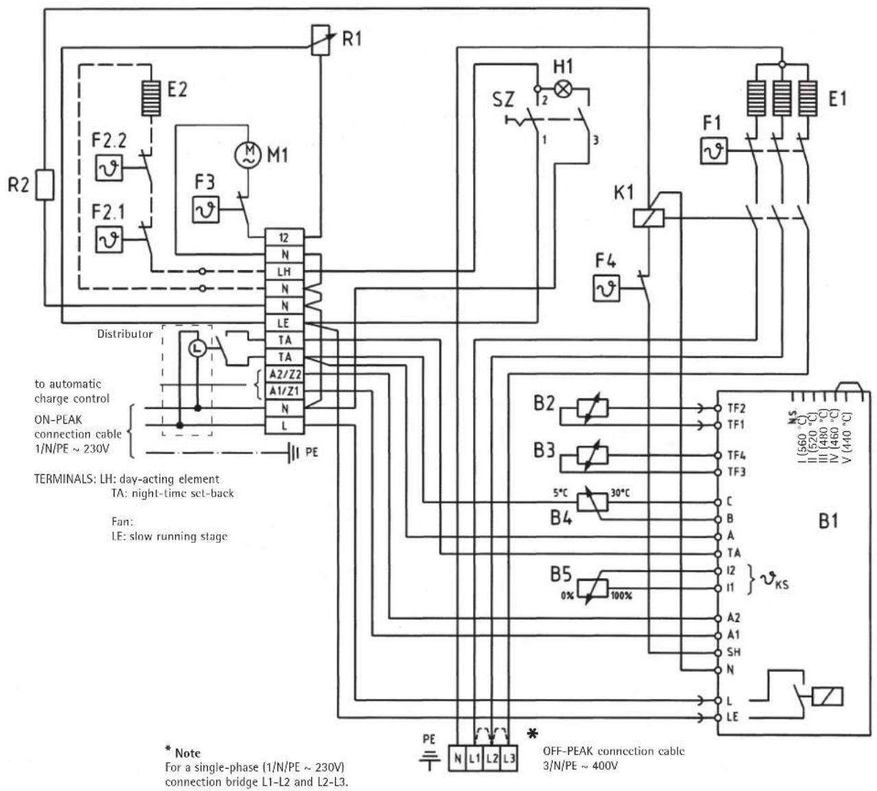
B1 Charge and discharge control
B2 Room temperature sensor
B3 Core sensor PT100
B4 Room temperature adjuster 47 kOhm
B5 Charge intensity adjuster 47 kOhm
E1 Heating elements 3 × 1,0kW
E2 Day-acting element
F1 Non-resetting safety cut-out
F2.1 Day-acting element switching
F2.2 Day-acting element safely cut-out
F3 Fan non-resetting safety cut-out
F4 Charge temperature regulator
H1 Day-acting element signal lamp
K1 Thermal relay
M1 Fan
R1 Fan compensatory resistance 450 Ohm / 25 W
R2 Safety resistance 22 Ohm
SZ Day-acting element switch
Caution! Voltage may still be applied on the high-tariff terminals, especially terminals A1/Z1 and A2/Z2 from the central charge control, even if the heater circuit breakers are switched off.
Caution! There must be a continuous voltage (ON-PEAK connection cable) on terminals L and N in order to supply the electronic charge and discharge control and fan.
2.3.6 Installation of heater core and elements
- Slide the kitchen heater into its recess (move to its final position) and adjust. If necessary, adjust the screw feet.
- Install the storage core bricks so that the openings in the bricks correspond to those in the floor insulation and are flush with the step in the front of the floor insulation (Fig. 9 + 10).
When installing the final layer of bricks, set the core-cover plate (Pos. 6, Fig. 9) with the edge pointing downwards and towards the heater rear and such, that it lies between the storage core and the top insulation. The cover plate can no longer be pulled forwards out of the heater.
- Push the heating element E1 (Fig. 9 + 10) from the front between the storage bricks as far to the rear as it can go.
-
Set the insulation from the front firmly between the ends of the heating elements.
-
Install the inside front panel (Fig. 11): To do this, first push the panel carefully over the heating element ends E1 on the left-hand side and then lift it over the heating element ends on the right-hand side. Fix the inside panel on the side and top with 8 screws (Pos. 7).
- Replace the insulation that has been pushed outwards by the heating elements. The oval-shaped insulating washers provided are then pushed over the ends of the heating elements and twisted so that they are firmly fixed behind the inside panel.
- Replace the high-temperature safety cut-out F1 and Thermostat F4 (Fig. 11).
- The free ends of the safety cut-out F1 cables and the free N-bridge on the switching plate (page 31) are to be connected to the heater elements E1 according to the circuit diagram.
Note: Once the storage core has been installed and the heating elements have been connected, bend the fan resistance R1 with holding bracket on the switching plate to a horizontal position. Make sure that the ends of the heating elements are not in contact with any internal wiring.
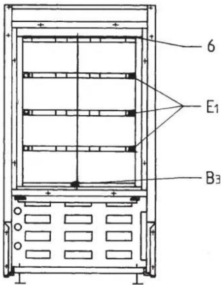
Fig. 9
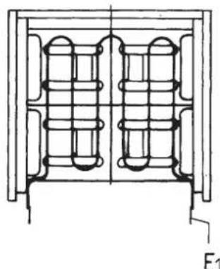
Fig. 10
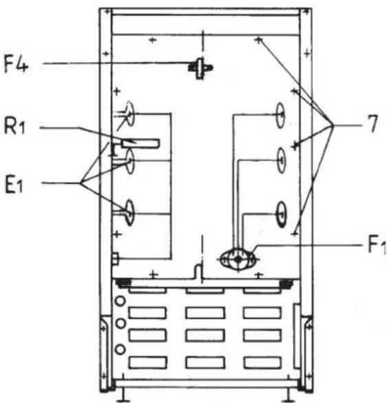
Fig. 11
2.3.7 Installation of fan compartment and base board
- Clean out the base of the kitchen heater before installing the fan compartment (slide-in module).
- Set the fan compartment, along with the base board, back into the heater. Fix the fan compartment with 2 fixing screws on the underside of the inside panel (Pos. 4, Fig. 12).
- Reconnect the fan wires to the switching plate.
- Reconnect the room temperature sensor B2 wires to the charge and discharge regulator B1
- If a Day Acting Element (DAE) has been fitted, replace the DAE release thermostat F2.1 to the inside side panel and reconnect the DAE wiring to the switching plate.
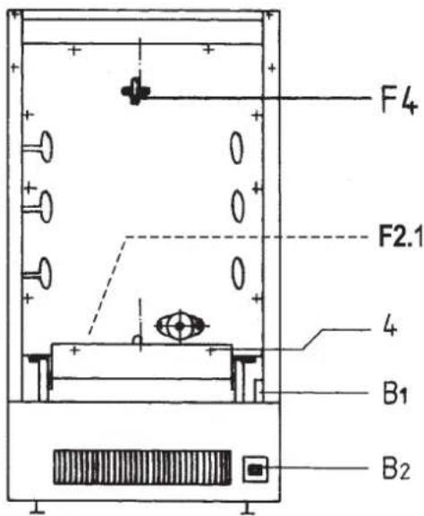
Fig. 12
Caution: Make sure that no wiring is damaged or removed or is touching the fan resistance. Run the wires in such a way that this does not happen.
In order to adjust the black base board to the respective fitted base recess, remove both pressure screws at the left and right hand front side of the fan compartment (Pos. 8, Fig.13).
- Adjust the base board to the respective base recess. Re-fix the pressure screws.
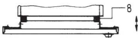
Fig. 13
Note: The black base board (with insert for air outlet) can also be individually removed from the heater. This is necessary, for instance, when a day-acting element is to be fitted. To do this, remove the room temperature sensor B2 connecting wires from the charge and discharge regulator B1. Remove the pressure screws on the fan compartment and pull the base board outwards from the heater.
2.3.8 Installation of kitchen unit front and adjusting boards
Measure the dimension "H" from the floor to the recess in the side panel (Fig. 14).
- Measure the dimension "S" from the floor to the lower surface of the kitchen unit front (Pos.9, Fig. 14).
Calculate dimension "X" (= H - S)
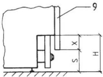
Fig. 14
- Drill four tapping holes 0.5mm , 8mm deep (see Fig. 15) on the rear of the kitchen unit front according to the sketch Fig. 16.
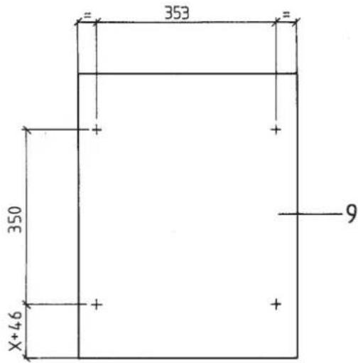
Fig. 15
- Hammer in the expanding spring sleeve M4 (Pos. 10, Fig. 16) flush into the tapping holes in the kitchen unit front.
- Prefix the threaded pin M4 x 18 (Pos. 11) with 1 each moulding bolt (Pos. 12), 2 washers (Pos. 13) and 1 nut (Pos. 14) and screw them completely into the expanding spring sleeve.
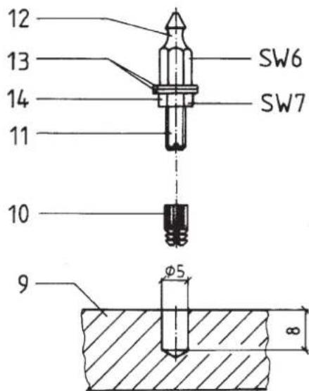
Fig. 16
- Mount the adjusting board(s) 10mm or 20mm , whichever necessary and fix them with the M4 screws (Pos. 15, Fig. 17) and nuts (Fig. 18) onto the operating plate (Pos. 17) according to the height of the kitchen unit base board.
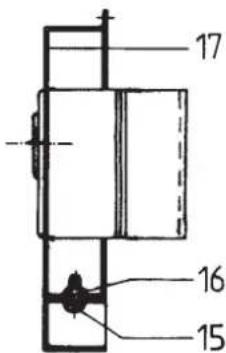
Fig. 17
Caution: Before replacing the front cover panel, make sure that the core temperature sensor B3 (see Fig. 6, Page 32) is firmly sitting in its sleeve (sensor tip at end of sleeve).
- Position the spring clips (Pos. 18, Fig. 18) from the rear into the 4 square holes in the front cover panel. Replace the cover panel onto the heater and fix with the screws.
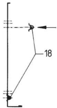
Fig. 18
Caution: Make sure that the spring clips cannot come into contact with the fan compensatory resistance. Bend the compensatory resistance into a horizontal position. Electrical safety!
- Replace and fix the operating plate. Place the kitchen unit front in position.
Note: The kitchen unit front can also be fixed with locking screws. Screw holes for these are already cut into the front cover panel. However, the kitchen unit front panel must be fixed before the operating panel is replaced.
2.4 Rating Label
The rating label contains technical data specific to the type of appliance. The rating label is found at the bottom left of the black base board.
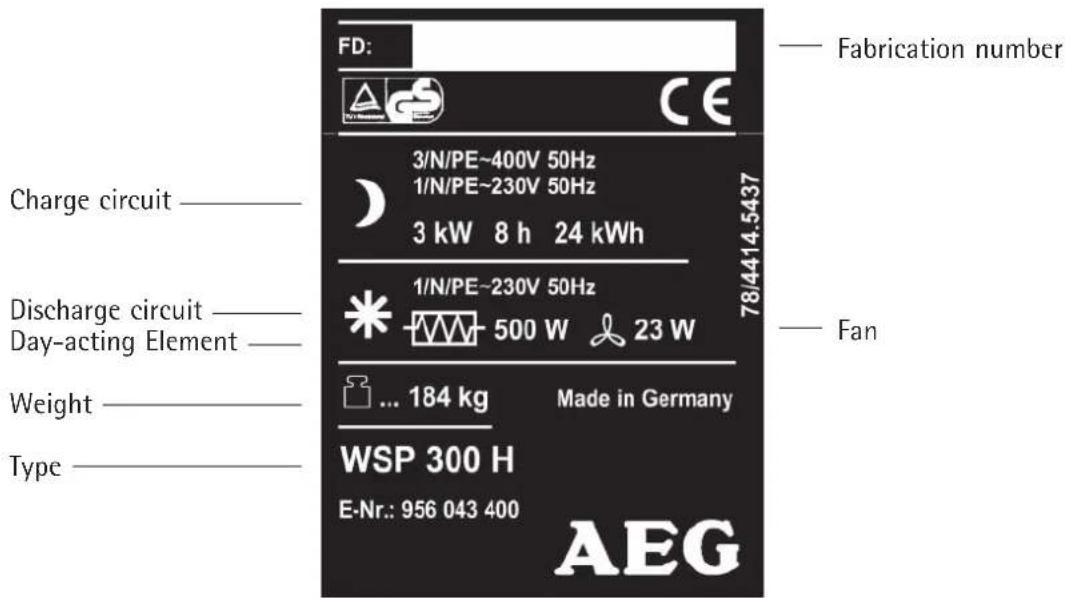
Fig. 19
2.5 Spare parts
When ordering spare parts, always give the type and fabrication number which is printed on the rating label.
We recommend writing the fabrication number here whilst installing the heater:
Type number: WSP 300 H
Fabrication number:
2.6 Accessories
2.6.1 Full decoration set
The full decoration set allows the kitchen heater to stand alone, without integration into a built-in kitchen unit.
The set consists of a front panel, cover panel with working top and 2 side panels.
Installation
- Remove the operating panel and front cover panel (see Steps 1 - 3, page 28).
- Remove the black base board (with fitted airoutlet):
To do this, remove the connecting wires of the room temperature sensor B2 from the charge and discharge regulator B1 (see Fig. 12 + 13, page 33). Loosen the pressure screws (Pos. 8) on the fan compartment and pull the base board forwards out of the heater.
Fix the side panels (Pos. 19, Fig. 20) to the bottom of the left and right side panels.
- Offer up the cover panel, placing the key-holes in its fixing rail over the countersunk screws (Pos. 20) in the heater cover plate. Push the cover panel back so far, that it overhangs ca. 30mm on the front or rear side. Screw the cover plate in position from below through the heater cover panel in the fixing holes (Pos. 21). Use the screws provided to do this.
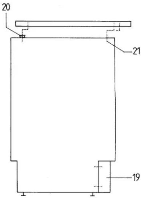
Fig. 20
Fix an adjusting panel 20mm in height to the operating panel (Pos. 23, Fig. 21).
- Replace the base board flush to the side panels. Replace the room temperature sensor B2 connecting cables to the charge and discharge regulator B1. Re-fix the pressure screws.
Caution: Before replacing the front cover panel, make sure that the core temperature sensor B3 (see Fig. 6, page 32) is firmly sitting in its sleeve (sensor tip at end of sleeve).
- Replace and fix the front cover panel.
- Place the front panel with the key-holes over the 4 countersunk screws (Pos. 22) in the side panels and push downwards until they click into place.
- Replace and fix the operating plate (Pos. 23).
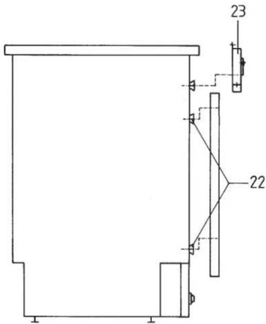
Fig. 21
2.6.2 Day-acting Element
Using the day-acting element the heater can give off warmth immediately even if it is not charged at all. The day-acting element works on the ON-PEAK Tariff.
The day-acting element is operated by the integrated rocker switch. The rocker switch lights up when the day-acting element is operating.
The day-acting element may only be installed by an authorised electrician.
Installation
- Cut off all power supplies to the kitchen heater.
- Remove the operating panel and front cover panel (see Steps 1 - 3, page 28).
- Remove the black base board (with fitted air-outlet): To do this, remove the connecting wires of the room temperature sensor B2 from the charge and discharge regulator B1 (see Fig. 12 + 13, page 33). Loosen the pressure screws (Pos.8) on the fan compartment and pull the base board forwards out of the heater.
Fix the "switching thermostat" F2.1 (Fig. 22) above the fan compartment (Pos. 24) by screwing it in the holes provided in the lower left hand side of the inside panel.
Fix the "safety cut-out" F2.2 (Fig. 23) by screwing it in the holes provided on the fan compartment (slide-in fan module).
Note: The "switching thermostat" and "safety cut-out" are identical components.
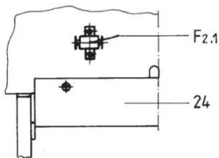
Fig. 22
- Remove the screws (Pos. 25, Fig. 23) from the top part of the slide-in fan module.
- Remove the tape covering the cable conduit hole and insert the cable conduit from the outside (Pos, 26).
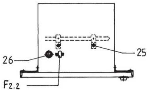
Fig. 23
- Position the day-acting element E2 (Fig. 24) from the rear into the slide-in fan module, threading the cable ends to the outside. Position the element holding lugs accordingly and fix them with the screws provided.
- Screw the earth wire (Pos. 27) into position on the front left hand side of the slide-in fan module.
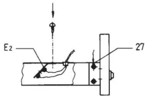
Fig. 24
- Replace the base board. Reconnect the room temperature sensor B2 cables to the charge and discharge regulator B1. Retighten the pressure screws.
- Connect the earth wire to the switching panel. Connect up the cables from the "switching thermostat", the "safety cut-out" and the day-acting element according to the circuit diagram (page 31).
Caution: Make sure that no wiring is damaged or removed or is touching the fan resistance. Run the wires accordingly, so that this does not happen.
Caution: Before replacing the front cover panel, make sure that the core temperature sensor B3 (see Fig. 6, page 32) is firmly sitting in its sleeve (sensor tip at end of sleeve).
- Replace the front cover panel and the operating panel.
- Reconnect the power supplies and check the function of the day-acting element.
2.7 Commissioning the Heater
Following tests must be carried out before commissioning the heater:
Insulation test with a voltage of at least 500V The dielectric resistance must be at least 0,5 MOhm.
- The electrical installer must measure the power draw of the elements. This can be done using a kW and time measurement or alternatively by measuring the cold element resistance. The value is to be compared with that of the rating label or in the "Technical Data" Section.
Note:
During the first charging periods the machine oils various used in manufacture, as well as dust particles accumulated during manufacture and storage burn off, causing an unpleasant odour.
Make certain the room is well ventilated.
2.8 Re-assembly
Heaters that have already been in operation or have been taken apart and repositioned must be reinstalled according to these instructions. The commissioning tests described on this page must also be carried out.
The first charging cycle after re-assembly must be monitored by the installer until the charge control switches off the elements.
Any insulation parts which are, or seem to be, damaged or have changed properties which could influence their function and safety, must be replaced.
3. Guarantee

For guarantee please refer to the respective terms and conditions of supply for your country.
The installation, electrical connection and first operation of this appliance should be carried out by a qualified installer.
The company does not accept liability for failure of any goods supplied which are not installed in accordance with the manufacturer's instructions.
3.1 Environment and recycling
Please help us to protect the environment by disposing of the packaging in accordance with the national regulations for waste processing.
2.5 Reservenderdelen


- Electric Storage Heaters
- WSP 300 H
- François
- Contenu
- Operating Instructions
- Technical Description
- Operation
- Heat storage
- Automatic charge control
- Manual charging
- Heat discharge
- Day-acting element heater switch
- Summer operation
- Energy saving tips
- Important Instructions
- Care and Maintenance
- Important note
- General
- This instruction leaflet must be:
- Defects
- Trouble Shooting Tips
- Heater does not store heat
- Heater always on full charge
- Appliance does not give out enough heat
- Characteristic curve of the core and room temperature sensors
- Installation instructions
- Technical Data
- Heater Positioning and Installation
- Procedures to be followed
- Choosing the Heater Position
- Regulations governing heater position
- Heater dimensions, fitting measurements
- Assembly and Electrical Connection
- Opening the heater
- Adjusting the heater to working-top height
- Running in the supply cables
- Electrical connection
- Circuit diagram WSP 300 H
- Installation of heater core and elements
- Installation of fan compartment and base board
- Installation of kitchen unit front and adjusting boards
- Rating Label
- Spare parts
- Accessories
- Full decoration set
- Installation
- Day-acting Element
- Commissioning the Heater
- Note:
- Re-assembly
- Guarantee
- Environment and recycling
- Reservenderdelen
Brand : AEG
Model : WSP 300 H
Category : Heating