Infra Fix Performant - Heating BARBECOOK - Free user manual and instructions
Find the device manual for free Infra Fix Performant BARBECOOK in PDF.
Frequently Asked Questions - Infra Fix Performant BARBECOOK
User questions about Infra Fix Performant BARBECOOK
0 question about this device. Answer the ones you know or ask your own.
Ask a new question about this device
Download the instructions for your Heating in PDF format for free! Find your manual Infra Fix Performant - BARBECOOK and take your electronic device back in hand. On this page are published all the documents necessary for the use of your device. Infra Fix Performant by BARBECOOK.
USER MANUAL Infra Fix Performant BARBECOOK
natural_image
Line drawing of a portable outdoor heater with a cylindrical base and top-mounted dish (no text or symbols)NOMAD FIX SPIDER
natural_image
Simple line drawing of a vertical outdoor lamp with a canopy and base (no text or symbols)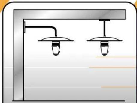
natural_image
Diagram of two ceiling-mounted lighting fixtures with hanging lights and a pipe (no text or symbols)IT ISTRUZIONI DI USO E MONTAGGIO
FR MODE D'EMPLOI ET INSTRUCTIONS
DE GEBRAUCHSANLEITUNG UND DIE AUFBAUANLEITUNG
NL HANDLEIDING EN GEBRUIKSAANWIJZING
ES MODO DE EMPLEO E INSTRUCCIONES
UK USER MANUAL AND ASSEMBLY INSTRUCTIONS
PT AS INTROÇÕES DE MONTAGEM E FONCIONAMENTO
NO BRUKS-OG MONTERINGSANVISNING
SE MONTERINGS- OCH BRUKSANVISNING
FI PAKKAUKSESSA ON GRILLIN
IS BAEKLINGUR OG SAMSETNINGAR LEI_BEININGAR

text_image
Fig. A INFRA SPIDER CLASSIC/PERFORMANT (CI+B1) INFRA FIX CLASSIC/PERFORMANT (C+B+A1) INFRA FIX CLASSIC/PERFORMANT (C+B+A2) INFRA NOMAD CLASSIC/PERFORMANT (C+B+A3) INFRA FIX CLASSIC INFRA NOMAD CLASSIC/PERFORMANT (C+B+A4) INFRA FIX CLASSIC INFRA NOMAD CLASSIC/PERFORMANT (C+B+A5) INFRA FIX CLASSIC INFRA NOMAD CLASSIC/PERFORMANT (C+B+A6) INFRA FIX CLASSIC INFRA NOMAD CLASSIC/PERFORMANT (C+B+A7) INFRA FIX CLASSIC INFRA NOMAD CLASSIC/PERFORMANT (C+B+A8) INFRA FIX CLASSIC INFRA NOMAD CLASSIC/PERFORMANT (C+B+A9) INFRA FIX CLASSIC INFRA NOMAD CLASSIC/PERFORMANT (C+B+A10) INFRA FIX CLASSIC INFRA NOMAD CLASSIC/PERFORMANT (C+B+A11) INFRA FIX CLASSIC INFRA NOMAD CLASSIC/PERFORMANT (C+B+A12) INFRA FIX CLASSIC INFRA NOMAD CLASSIC/PERFORMANT (C+B+A13) INFRA FIX CLASSIC INFRA NOMAD CLASSIC/PERFORMANT (C+B+A14) INFRA FIX CLASSIC INFRA NOMAD CLASSIC/PERFORMANT (C+B+A15) INFRA FIX CLASSIC INFRA NOMAD CLASSIC/PERFORMANT (C+B+A16) INFRA FIX CLASSIC INFRA NOMAD CLASSIC/PERFORMANT (C+B+A17) INFRA FIX CLASSIC INFRA NOMAD CLASSIC/PERFORMANT (C+B+A18) INFRA FIX CLASSIC INFRA NOMAD CLASSIC/PERFORMANT (C+B+A19) INFRA FIX CLASSIC INFRA NOMAD CLASSIC/PERFORMANT (C+B+A20) INFRA FIX CLASSIC INFRA NOMAD CLASSIC/PERFORMANT (C+B+A21) INFRA FIX CLASSIC INFRA NOMAD CLASSIC/PERFORMANT (C+B+A22) INFRA FIX CLASSIC INFRA NOMAD CLASSIC/PERFORMANT (C+B+A23) INFRA FIX CLASSIC INFRA NOMAD CLASSIC/PERFORMANT (C+B+A24) INFRA FIX CLASSIC INFRA NOMAD CLASSIC/PERFORMANT (C+B+A25) INFRA FIX CLASSIC INFRA NOMAD CLASSIC/PERFORMANT (C+B+A26) INFRA FIX CLASSIC INFRA NOMAD CLASSIC/PERFORMANT (C+B+A27) INFRA FIX CLASSIC INFRA NOMAD CLASSIC/PERFORMANT (C+B+A28) INFRA FIX CLASSIC INFRA NOMAD CLASSIC/PERFORMANT (C+B+A29) INFRA FIX CLASSIC INFRA NOMAD CLASSIC/PERFORMANT (C+B+A30) INFRA FIX CLASSIC INFRA NOMAD CLASSIC/PERFORMANT (C+B+A31) INFRA FIX CLASSIC INFRA NOMAD CLASSIC/PERFORMANT (C+B+A32) INFRA FIX CLASSIC INFRA NOMAD CLASSIC/PERFORMANT (C+B+A33) INFRA FIX CLASSIC INFRA NOMAD CLASSIC/PERFORMANT (C+B+A34) INFRA FIX CLASSIC INFRA NOMAD CLASSIC/PERFORMANT (C+B+A35) INFRA FIX CLASSIC INFRA NOMAD CLASSIC/PERFORMANT (C+B+A36) INFRA FIX CLASSIC INFRA NOMAD CLASSIC/PERFORMANT (C+B+A37) INFRA FIX CLASSIC INFRA NOMAD CLASSIC/PERFORMANT (C+B+A38) INFRA FIX CLASSIC INFRA NOMAD CLASSIC/PERFORMANT (C+B+A39) INFRA FIX CLASSIC INFRA NOMAD CLASSIC/PERFORMANT (C+B+A40) INFRA FIX CLASSIC INFRA NOMAD CLASSIC/PERFORMANT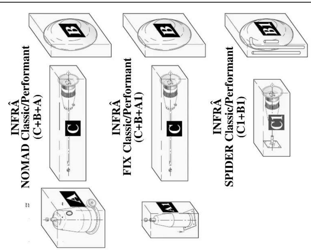
text_image
INFRA SPIDER CLASS/Perform (C1+B1) INFRA FIX CLASS/Perform (C+B+A1) INFRA ONMAD CLASS/Perform (C+B+A)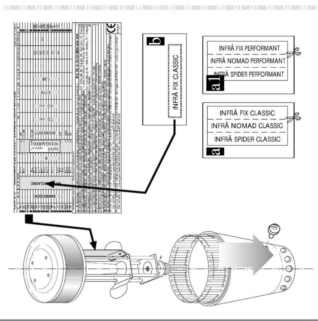
text_image
INFRÄ FIX PERFORMANT INFRÄ NOMAD PERFORMANT INFRÄ SPIDER PERFORMANT INFRÄ FIX CLASSIC INFRÄ NOMAD CLASSIC INFRÄ SPIDER CLASSIC INFRÄ FIX CLASSIC INFRÄ NO. 10000000000000000000000000000000000000000000000000000000000000000000000000000000000000000000000000000 a1 b c d e f g h i j k l m n o p q r s t u v w x y z a1 b1 c1 d1 e1 f1 g1 h1 i1 j1 k1 l1 m1 n1 o1 p1 q1 r1 s1 t1 u1 v1 w1 x1 y1 z1 a2 b2 c2 d2 e2 f2 g2 h2 i2 j2 k2 l2 m2 n2 o2 p2 q2 r2 s2 t2 u2 v2 w2 x2 y2 z2 a3 b3 c3 d3 e3 f3 g3 h3 i3 j3 k3 l3 m3 n3 o3 p3 q3 r3 s3 t3 u3indice/index
UK USER MANUAL AND ASSEMBLY INSTRUCTIONS pag. 58
text_image
MIN 2 m MAX 2310mm h MAX 2180mm Class h MAX 2245mm h MIN 2115mm MIN 2 m MIN 2 m MIN 0.5m Ø 855mm MIN 0.5m MIN 1.5m Fig. 1 B NOMAD C SPIDER Rmax = 2.5m MIN 2m Ø 530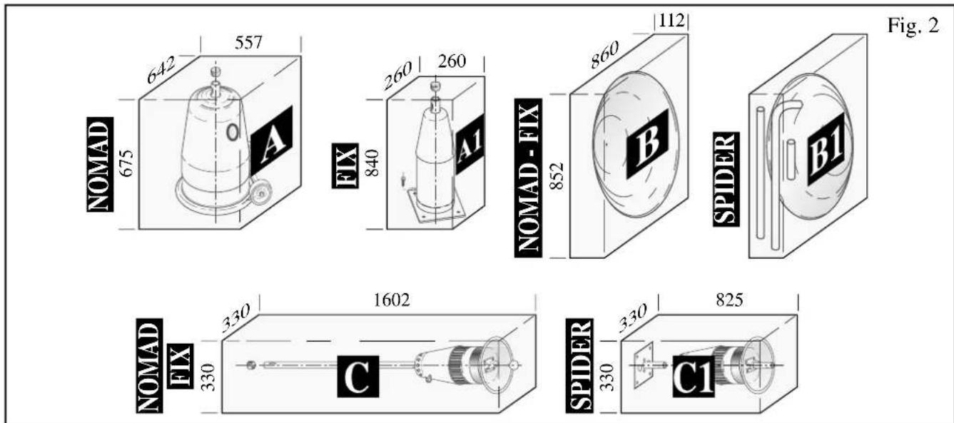
text_image
Fig. 2 642 557 675 A FIX 260 260 840 B 112 860 852 SPIDER B1 NOMAD-FIX NOMAD FIX 330 330 1602 C SPIDER 330 825 C1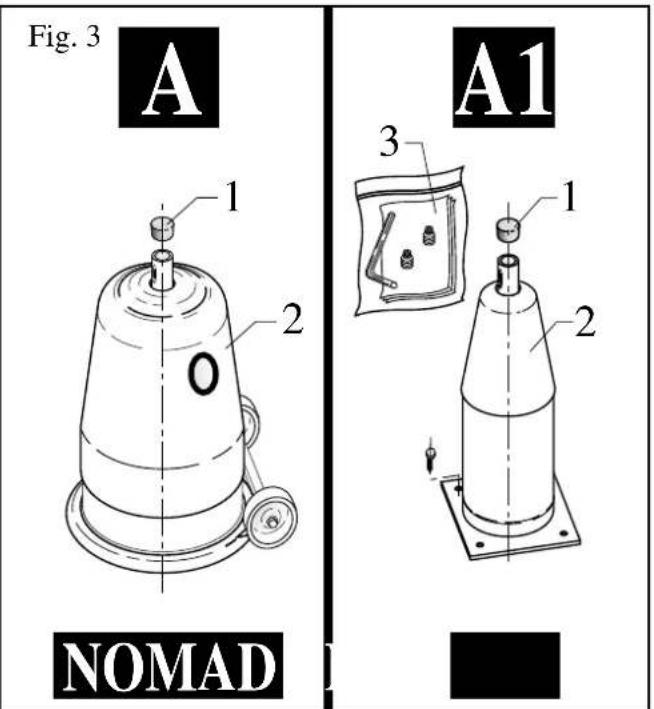
text_image
Fig. 3 A 1 2 0 A1 3 1 2 NOMAD
text_image
B FIX NOMAD B1 Fig. 4 SPIDERFig. 5

NOMAD - FIX - SPIDER
text_image
Technical diagram of a mechanical device with numbered components and a close-up inset showing internal structure.Fig. 6
NOMAD

text_image
Technical diagram showing a mechanical assembly with labeled parts and directional arrows indicating motion or assembly.
text_image
Technical diagram of a mechanical device with labeled parts and directional arrows indicating assembly or motion.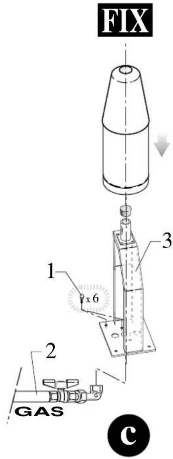
text_image
FIX 1 x 6 2 GAS cFig. 7
NOMAD

text_image
LPG GPLNOMAD

text_image
1 2 3 GPL LPGa
DMAD - FIX
text_image
5 1 4 3 2 b1 3SPIDER
text_image
Technical diagram of a mechanical device with labeled components and assembly stepsFig. 8
Fig. 9
NOMAD
text_image
1 OA
The image is too blurry to recognize any text content.

text_image
Technical diagram showing a mechanical assembly with labeled components and directional arrows indicating motion or assembly.A1
SPIDER

text_image
1 2 3 a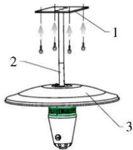
text_image
1 2 3b
C1
text_image
Fig. 10 1 2 A NOMAD 1 2 A1
text_image
NOMAD 1 2 3
text_image
NOMAD Fig. a = 210mm b = 367mm C_MAX = 695mm C_MIN = 568mm
text_image
13 a = 80mm b = 169mm c = 695mm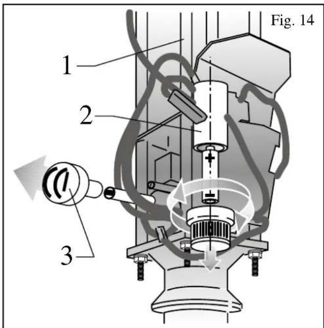
text_image
Fig. 14 1 2 3
flowchart
graph TD
    A["MIN"] -->|OFF| B["MAX"]
    B --> C["PUSH"]
    C --> D["MAX"]
    D --> E["MIN OFF"]
    E --> F["Switch"]
    style A fill:#f9f,stroke:#333
    style B fill:#ccf,stroke:#333
    style C fill:#cfc,stroke:#333
    style D fill:#fcc,stroke:#333
    style E fill:#cff,stroke:#333
    style F fill:#ffc,stroke:#333
| SAEY N.V. INDUSTRIELAAN 4 B-8 50 1 KORTRIJK-HEULE BELGIUM - MADE IN ITALY - | |||||||||||||||
| A | B C D E F G | H | kW | l kW | L m3/h | M ∅ mm | N ∅ mm | O G20 mbar | P G25 mbar | Q | |||||
| ● AT | - | INFRÄ FIX CLASSICINFRÄ SPIDER CLASSIC | 12H | - | - | 20 - AT | ● | ||||||||
| ● BE | - | 12E+ | - | - | 20 25 BE | ● | |||||||||
| ○ CH | - | - | - | - | - | - | - | ○ | |||||||
| ○ CZ | - | - | - | - | - | - | - | ○ | |||||||
| ● DE | - | 12E | - | - | 20 20 DE | ● | |||||||||
| ● DK | 12H | - | 20 | - | ● DK | ||||||||||
| ● ES | 12H | - | 20 | - | ● ES | ||||||||||
| ● FI | 12H | - | 20 | - | ● FI | ||||||||||
| ● FR | 12E+ | - | 20 | 25 | ● FR | ||||||||||
| ● GB | 12H | A | - | 20 | - | ● GB | |||||||||
| ● GR | 12H | - | 20 | - | ● GR | ||||||||||
| ○ HU | - | - | - | - | ○ HU | ||||||||||
| ● IE | 12H | - | 20 | - | ● IE | ||||||||||
| ● IS | - | - | - | - | ● IS | ||||||||||
| ● IT | 12H | - | 20 | - | ● IT | ||||||||||
| ● LU | - | 12E | - | - | 20 - LU | ● | |||||||||
| ● NL | - | 12L | - | - | - | - | - | - | - | - | 25 | ● NL | |||
| ● NO | - | 12H | - | - | 20 - NO | ● | |||||||||
| ● PT | - | 12H | - | - | 20 - PT | ● | |||||||||
| ● SE | - | 12H | - | - | 20 - SE | ● | |||||||||
| LEGENDA colonne: - Columnes esplication | |||||||||||||||
| A...Q: Sigla Paese - Land identification - désignation du pays - Landesbezeichnung - Indicacao do pais - Land van bestemming ● SI, YES, JA, OUI ○ NO, NEEN, NEIN, NON | |||||||||||||||
| B: serie apparecchio - appliance serial- serie de l'appareil- Serie des Geräts - série aparelho - serie aparato - Merk | |||||||||||||||
| C: modello apparecchio - appliance model - serie aparato - Modell des Geräts -modelo aparelho - modelo aparato - Model | |||||||||||||||
| D: categoria gas - gas categories - type de gaz - Gaskategorie - categoria de gas - categoria de gas - Gascategorie | |||||||||||||||
| E: tipo apparecchio - appliance type - type d'appareil - Typ des Geräts - tipo do aparelho - version aparato - Toesteltype | |||||||||||||||
| F: codice apparecchio - appliance code - code appareil - Kode Geräts - código aparelho - aparato código - Serienummer | |||||||||||||||
| G: numero codice PIN - NIP number - numero de code PIN - PIN-Kodenummer - numero de código PIN - numero de codificacion PIN - PIN code | |||||||||||||||
| H: portata termica nominale - nominal heat input - débit calorifique nominal - Nennbelastung - carga nominal - carga nomina - Nominale belasting | |||||||||||||||
| I: portata termica ridotta - reduced heat input - débit calorifique minimal - Mindestbelastung - carga minima - carga minima - Minimum belasting | |||||||||||||||
| L: consumo orario gas - gas consonction - consommation de gaz - Gasverbrauch - consumo de gas - consumo de gas - Consumptie | |||||||||||||||
| M: diametro ugello - injector diameter - diamètre du gicleur - Durchmesser Einspritzdüse - diametro do injector - diametro inyector - Diameter inspuiter | |||||||||||||||
| N: diametro diaframma - diafragme diameter - diamètre du diaphragme - é Durchmesser Blende - Diâmetro do diafragma - diâmetro diafragma - Diameter diafragma |  | ||||||||||||||
| O: press. alim. METANO G20 - inlet gas pressure NATURAL GAS G20 - pression de gaz entrante GAZ NATUREL G20 - Eintrittsgasdruck ERDGAS G20 - pressão do gas de entrada GAS NATURAL G20 - presión gas entrante GAS NATURAL G20 - Gasdruk inlaat METHANE G20 | |||||||||||||||
| P: press. alim. METANO G25 - inlet gas pressure NATURAL GAS G25 - pression de gaz entrante GAZ NATUREL G25 - Eintrittsgasdruck ERDGAS G25 - pressão do gas de entrada GAS NATURAL G25 - presión gas entrante GAS NATURAL G25 - Gasdruk inlaat METHANE G25 | 0 6 9 4 /00 | ||||||||||||||
0694/00
Tab.1
| SAEY N.V. INDUSTRIELAAN 4B-8501 KORTRIJK-HEULE BELGIUM - MADE IN ITALY | ||||||||||||||
| A | B C | D E F G | H | kW | I kW | L g/ h | M ∅ mm | N ∅ mm | O Q30 mbar | P G31 mbar | Q | |||
| ● AT | - | INFRÄ NOMAD CLASSIC INFRA FIX CLASSIC INFRA SPIDER CLASSIC | ■BB/ P | - | - | - | - | - | - | - | 1,40 | 50 | 50 | ● AT |
| ● BE | - | ■3+ | - - - - - - - - - - - - - - - - - - - - - - - - - - - - - - - - - - - - - - - - - - - - - - - - - - - - - - - - - - - - - - - - - - - - - - - - - - - - - - - - - - - - - - - - - - - - - - - - - - - - - | |||||||||||
| ○ CH | - | - | - | - | - | - | - | - | - | - | - | - | ○ | |
| ○ CZ | - | - | - | - | - | - | - | - | - | - | - | - | ○ | |
| ● DE | - | ■BB/ P | - | - | - | - | HS | - | - | 1,40 | 50 | 50 | ● DE | |
| ● DK | - | ■BB/ P | - | - | - | - | HS | - | - | - | 30 | 30 | ● DK | |
| ● ES | - | ■3+ | - | - | - | - | HS | - | - | - | 28.30 | 37 | ● ES | |
| ● FI | - | ■BB/ P | - | - | - | - | HS | - | - | - | 30 | 30 | ● FI | |
| ● FR | - | ■3+ | - | - | - | - | HS | - | - | - | 28.30 | 37 | ● FR | |
| ● GB | - | ■3+ | - | - | - | - | HS | - | - | - | 28.30 | 37 | ● GB | |
| ● GR | - | ■3+ | - | - | - | - | HS | - | - | - | 28.30 | 37 | ● GR | |
| ○ HU | - | - | - | - | - | - | HS | - | - | - | - | - | ○ HU | |
| ● IE | - | ■3+ | - | - | - | - | HS | - | - | - | 28.30 | 37 | ● IE | |
| ● IS | - | ■3B/ P | - | - | 0694BL2877 | 7,5 (Hs) | 4,0 (28-30/37 mbar) | G30: 545 G31: 536 | 1,30 | - | 30 | 30 | ● IS | |
| ● IT | - | ■3+ | - | - | - | - | HS | 4,5 (50 mbar) | - | - | 28.30 | 37 | ● IT | |
| ● LU | - | ■3P | - | - | - | - | HS | - | - | 1,40 | - | 50 | ● LU | |
| ● NL | - | ■BB/ P | - - - - - - - - - - - - - - - - - - - - - - - - - - - - - - - - - - - - - - - - - - - - - - - - - - - - - - - - - - - - - - - - - - - - - - - - - - - - - - - - - - - - - - - - - - - - - - - - - - | |||||||||||
| ● NO | - | ■BB/ P | - - - - - - - - - - - - - - - - - - - - - - - - - - - - - - - - - - - - - - - - - - - - - - - - - - - - - - - - - - - - - - - - - - - - - - - - - - - - - - - - - - - - - - - - - - | |||||||||||
Tab.1b
| SAEY N.V. INDUSTRIELAAN 4 B-8501 KORTRIJK-HEULE BELGIUM - MADE IN ITALY - | ||||||||||||||||
| A | B C D E F G | H | kW | I kW | L m3/h | M ∅ mm | N ∅ mm | O G20 mbar | P G25 mbar | Q | ||||||
| ● AT | - | INFRÄ FIX PERFORMANTINFRA SPIDER PERFORMANT | 12H | --- | ---- 20 - AT | ● | ||||||||||
| ● BE | - | 12E+ | --- | ---- 20 25 BE | ● | |||||||||||
| ○ CH | - | - | - | - | - | - | - | ○ | ||||||||
| ○ CZ | - | - | - | - | - | - | - | ○ | ||||||||
| ● DE | - | 12E | --- | ---- 20 20 DE | ● | |||||||||||
| ● DK | BARBECOOK | 12H | - | 20 | ● | DK | ||||||||||
| ● ES | 12H | - | - | 20 | - | ● | ES | |||||||||
| ● FI | 12H | - | - | 20 | - | ● | FI | |||||||||
| ● FR | 12E+ | - | - | 20 | 25 | ● | FR | |||||||||
| ● GB | 12H | A | 15 (Hs) | 1,428 | 20 | ● | GB | |||||||||
| ● GR | 12H | - | - | 20 | - | ● | GR | |||||||||
| ○ HU | - | - | - | - | ○ | HU | ||||||||||
| ● IE | 12H | - | 7,0 (Hs) | - | 20 | ● | IE | |||||||||
| ● IS | - | - | - | - | ● | IS | ||||||||||
| ● IT | 12H | - | - | 20 | ● | IT | ||||||||||
| ● LU | - | 12E | --- | ---- 20 - LU | ● | |||||||||||
| ● NL | - | 12L | - | - | - | - | - | - | - | - | - | 25 | ● | NL | ||
| ● NO | - | 12H | --- | ---- 20 - NO | ● | |||||||||||
| ● PT | - | 12H | --- | ---- 20 - PT | ● | |||||||||||
| ● SE | - | 12H | --- | ---- 20 - SE | ● | |||||||||||
| LEGENDA colonne: - Columnes esplication | ||||||||||||||||
| A....Q: Sigla Paese - Land identificaton - désignation du pays - Landesbezeichnung - Indicacao do pais - Land van bestemming ● SI, YES, JA, OUI ○ NO, NEEN, NEIN, NON | ||||||||||||||||
| B: serie apparecchio - appliance serial- serie de l'appareil- Serie des Geräts - série aparelho - serie aparato - Merk | ||||||||||||||||
| C: modello apparecchio - appliance model - serie aparato - Modell des Geräts -modelo aparelho - modelo aparato - Model | ||||||||||||||||
| D: categoria gas - gas categories - type de gaz - Gaskategorie - categoria de gas - categoria de gas - Gascategorie | ||||||||||||||||
| E: tipo apparecchio - appliance type - type d'appareil - Typ des Geräts - tipo do aparelho - version aparato - Toesteltype | ||||||||||||||||
| F: codice apparecchio - appliance code - code appareil - Kode Geräts -código aparelho - aparato códigio - Serienummer | ||||||||||||||||
| G: numero codice PIN - NIP number - numero de code PIN - PIN-Kodenummer - numero de códigio PIN - numero de codificación PIN - PIN code | ||||||||||||||||
| H: portata termica nominale - nominal heat input - débit calorifique nominal - Nennbelastung - carga nominal - carga nomina - Nominale belasting | ||||||||||||||||
| I: portata termica ridotta - reduced heat input - débit calorifique minimal - Mindestbelastung - carga minima - carga minima - Minimum belasting | ||||||||||||||||
| L: consumo orario gas - gas conuction - consommation de gaz - Gasverbrauch - consumo de gas - Consumptie | ||||||||||||||||
| M: diametro ugello - injector diameter - diamètre du gicleur - Durchmesser Einspritzdüse - diametro do injector - diametro inyector - Diameter inspuiter | ||||||||||||||||
| N: diametro diaframma - diafragme diameter - diamètre du diaphragme - é Durchmesser Blende - Diâmetro do diafragma - diâmetro diafragma - Diameter diafragma |  | |||||||||||||||
| O: press. alim. METANO G20 - inlet gas pressure NATURAL GAS G20 - pression de gaz entrante GAZ NATUREL G20 - Eintrittsgasdruck ERDGAS G20 - pressão do gas de entrada GAS NATURAL G20 - presión gas entrante GAS NATURAL G20 - Gasdruk iniaat METHANE G20 | ||||||||||||||||
| P: press. alim. METANO G25 - inlet gas pressure NATURAL GAS G25 - pression de gaz entrante GAZ NATUREL G25 - Eintrittsgasdruck ERDGAS G25 - pressão do gas de entrada GAS NATURAL G25 - presión gas entrante GAS NATURAL G25 - Gasdruk iniaat METHANE G25 | 0694/00 | |||||||||||||||
Tab.1c
| SAEY N.V. INDUSTRIELAAN 4B-8501 KORTRIJK-HEULE BELGIUM - MADE IN ITALY | |||||||||||||||
| A | B C | D E F G | H | kW | I kW | L g/h | M ∅ mm | N ∅ mm | O G30 mbar | P G31 mbar | Q | ||||
| ● AT | - | INFRÄ NOMAD PERFORMANTINFRA FIX PERFORMANTINFRÄ SPIDER PERFORMANT | |3B/ P | - | - | - | - | - | - | - | 2,00 | 50 | 50 | ● AT | |
| ● BE | - | |3+ | - | - | - | 37 | BE | ● | |||||||
| ○ CH | - | - | - | - | - | - | - | - | - | - | - | - | ○ | ||
| ○ CZ | - | - | - | - | - | - | - | - | - | - | - | - | ○ | ||
| ● DE | - | |3B/ P | - | - | 2,00 | 50 50 | DE | ● | |||||||
| ● DK | BARBECOOK | |3B/ P | - | - | (15) | 1,0 Hs | 1,090G31:1072 | ● DK | |||||||
| ● ES | - | |3+ | - | - | 30 | 30 | ● ES | ||||||||
| ● FI | - | |3B/ P | - | - | 28-30 | 37 | ● FI | ||||||||
| ● FR | - | |3+ | - | - | 30 | 30 | ● FR | ||||||||
| ● GB | - | |3+ | - | - | 28-30 | 37 | ● GB | ||||||||
| ● GR | - | |3+ | - | - | 28-30 | 37 | ● GR | ||||||||
| ○ HU | - | - | - | - | - | - | ○ HU | ||||||||
| ● IE | - | |3+ | - | - | 28-30 | 37 | ● IE | ||||||||
| ● IS | - | |3B/ P | - | - | 30 | 30 | ● IS | ||||||||
| ● IT | - | |3+ | - | - | 28-30 | 37 | ● IT | ||||||||
| ● LU | - | |3P | - | - | 2,00 - 50 | LU | ● | ||||||||
| ● NL | - | |3B/ P | - | 30 30 NL | ● | ||||||||||
| ● NO | - | |3B/ P | - | 30 30 | NO | ● | |||||||||
| ● PT | - | |3+ | - | - | 37 PT | ● | |||||||||
| ● SE | - | |3B/ P | - | - | SE | ● | |||||||||
Tab.1d
| DiaframmaDiafragmeDiaphragme | BlendeDiafragma | GAS G31 - 50 mbar |
| Modello apparecchioAppliance modelSerie aparatoModell des GerätsModelo aparelhoModelo aparatoModel | Diametro diaframmaDiafragme diameterDiamètre du diaphragmeé Durchmesser BlendeDiâmetro do diafragmadiâmetro diafragmaDiameter diafragma | n° di scanalaturenumber of groovesnombre de rainuresantal rillern° de ranurasnúmero de ranhurasaantal groeven |
| INFRAClassic7,5 kW | mm∅ 1,40 |  |
| INFRAPerformant15 kW | mm∅ 2,00 |  |
Tab. 2
text_image
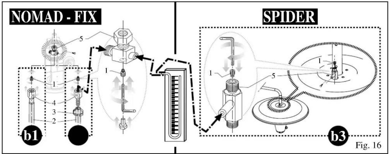
NOMAD - FIX b1 SPIDER b3 Fig. 16IT - ISTRUZIONI PER IL MONTAGGIO DEL DIAFRAMMA (vedi Tab. 2 e Fig. 16)
ATTENZIONE! NON MONTARE il diaframma sugli apparecchi alimentati a gas G30/ G31 29÷37 mbar.
IMPORTANTE! MONTARE il diaframma solo nel caso in cui sia previsto il funzionamento con pressione di alimentazione a 50 mbar (Austria, Germania, Lussemburgo).
Verificare quindi, la tipologia corretta come specificato e illustrato nella Tab. 2.
FR - INSTRUCTIONS POUR LE MONTAGE DU DIAPHRAGME (voir Tab. 2, Fig. 16)
ATTENTION! NE PAS MONTER de diaphragme sur les appareils à gaz G30/ G31 29 : 37 mbar.
IMPORTANT! NE MONTER le diaphragme qu'à condition que l'appareil soit supposé fonctionner à une pression d'alimentation de 50 mbar (Autriche, Allemagne, Luxembourg).
Vérifiez donc le type exact mentionné et illustré au Tab. 2.
DE - ANWEISUNGEN FÜR DIE MONTAGE DER MEMBRAN (Se Tab. 2, Abb. 16)
WICHTIG ! KEINE MEMBRANEN auf mit Gas angetriebenen Geräte montieren (G30/ G31 29:37mbar).
WICHTIG ! MEMBRAN nur montieren nachdem nachgeprüft wurde, ob das Gerät mit einem Speisungsdruck von 50 mbar funktioniert (Österreich, Deutschland, Luxemburg).
Kontrollieren Sie also zuerst den richtigen Typ in der Tabelle 2.
NL - INSTRUCTIES VOOR DE MONTAGE VAN HET DIAFRAGMA (zie Tab. 2, Fig. 16)
OPGELET! MONTEER GEEN diafragma op de toestellen op gas G30/ G31 29 : 37 mbar.
UK - DIAPHRAGM ASSEMBLY INSTRUCTIONS (see Tab. 2, Fig. 16)
ATTENTION! DO NOT INSTALL a diaphragm on the gas-run appliances G30/ G31 29 : 37 mbar.
IMPORTANT! Only INSTALL the diaphragm if the appliance is supposed to function with a supply pressure of 50 mbar (Austria, Germany, Luxembourg).
So, check the correct type mentioned and illustrated in Tab. 2.
PT - INSTRUÇÕES PARA A MONTAGEM DO DIAFRAGMA (veja Tabela 2, Fig. 16)
CAUTELA! NÃO MONTAR diafragma nos aparelhos a gás G30/ G31 29 : 37 mbar.
- Barbecook INFRÂ - - IT -
Indice
- Barbecook INFRÂ - - FR -
Table des matières
- DESCRIPTION GENERALE page 18
- MONTAGE page 19
- MISE EN MARCHE page 23
- EXTINCTION page 25
- ENTRETIEN page 25
- PROBLEMES page 26
- RANGEMENT page 26
- GARANTIE page 26
CONSERVEZ SOIGNEUSEMENT CE MANUEL TANT QUE VOUS DISPOSEZ DE VOTRE APPAREIL ! DEMANDEZ UN AUTRE EN CAS DE PERTE OU DE DÉGTS !
1 - DESCRIPTION GENERALE
- Barbecook INFRÂ - - DE -
Inhaltsverzeichnis
- Barbecook INFR - - NL -
inhoudsopgave
- Barbecook INFRÂ - - ES-
Índice
- Barbecook INFRÂ - - UK -
Contents
- GENERAL DESCRIPTION page 59
- ASSEMBLY page 60
- TURNING THE HEATER ON page 64
- TURNING THE HEATER OFF page 65
- MAINTENANCE page 66
- TROUBLESHOOTING page 66
- STORAGE page 67
- GUARANTEE page 67
CAREFULLY KEEP THIS MANUAL DURING THE ENTIRE SERVICE LIFE OF THE APPLIANCE! ASK FOR A COPY IF THE ORIGINAL MANUAL IS DAMAGED OR LOST!
1 - GENERAL DESCRIPTION
Thanks to its direct and reflected irradiation, the Barbecook INFRA can heat an area of approximately 20/25m² (Fig.1), naturally only in areas with sufficient ventilation such as terraces, pergolas, restaurants, bars and pubs that install the INFRA outdoors (in gardens, on pavements, etc).
The INFRA is very easy to use, was built in conformity with the European safety standards and has been tested and approved and is checked by the Notified Body that is entrusted with most of the manufacturer's certifications for products on gas.
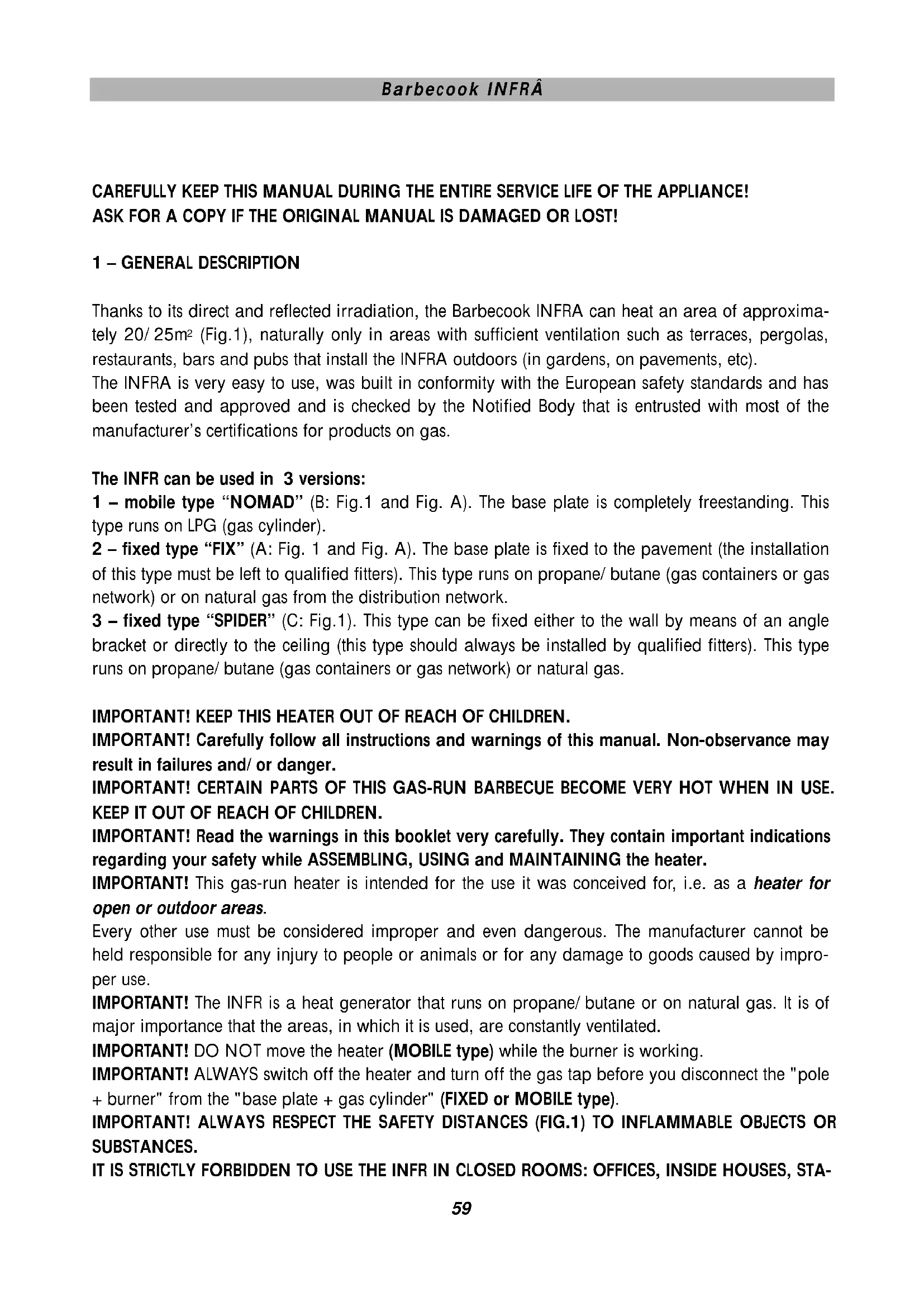
The INFR can be used in 3 versions:
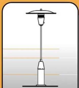
1 – mobile type “NOMAD” (B: Fig.1 and Fig. A). The base plate is completely freestanding. This type runs on LPG (gas cylinder).
2 – fixed type “FIX” (A: Fig. 1 and Fig. A). The base plate is fixed to the pavement (the installation of this type must be left to qualified fitters). This type runs on propane/ butane (gas containers or gas network) or on natural gas from the distribution network.
3 – fixed type “SPIDER” (C: Fig.1). This type can be fixed either to the wall by means of an angle bracket or directly to the ceiling (this type should always be installed by qualified fitters). This type runs on propane/ butane (gas containers or gas network) or natural gas.
IMPORTANT! KEEP THIS HEATER OUT OF REACH OF CHILDREN.
IMPORTANT! Carefully follow all instructions and warnings of this manual. Non-observance may result in failures and/or danger.
IMPORTANT! CERTAIN PARTS OF THIS GAS-RUN BARBECUE BECOME VERY HOT WHEN IN USE. KEEP IT OUT OF REACH OF CHILDREN.
IMPORTANT! Read the warnings in this booklet very carefully. They contain important indications regarding your safety while ASSEMBLING, USING and MAINTAINING the heater.
IMPORTANT! This gas-run heater is intended for the use it was conceived for, i.e. as a heater for open or outdoor areas.
Every other use must be considered improper and even dangerous. The manufacturer cannot be held responsible for any injury to people or animals or for any damage to goods caused by improper use.
IMPORTANT! The INFR is a heat generator that runs on propane/ butane or on natural gas. It is of major importance that the areas, in which it is used, are constantly ventilated.
IMPORTANT! DO NOT move the heater (MOBILE type) while the burner is working.
IMPORTANT! ALWAYS switch off the heater and turn off the gas tap before you disconnect the "pole + burner" from the "base plate + gas cylinder" (FIXED or MOBILE type).
IMPORTANT! ALWAYS RESPECT THE SAFETY DISTANCES (FIG.1) TO INFLAMMABLE OBJECTS OR SUBSTANCES.
IT IS STRICTLY FORBIDDEN TO USE THE INFR IN CLOSED ROOMS: OFFICES, INSIDE HOUSES, STA-
BLES, FARMS, PLACES SITUATED CLOSE TO GAS DAMPS OR INFLAMMABLE AND/ OR EXPLOSIVE DUST, ETC.
IMPORTANT! DURING THE ASSEMBLY, COMPLY WITH THE FIRE AND ACCIDENT PREVENTION REGULATIONS OF THE COUNTRY IN WHICH THE HEATER IS INSTALLED.
IMPORTANT! DO NOT use the heater in basements if it is pre-set to run on LPG.
2 - ASSEMBLY
Take all the parts out of their package. Be especially careful with the burner (C: Fig.2).
Check whether the contents of the packages is complete and in compliance with the list below (Fig.2). Follow the regulations in force when throwing away the packages.
Inspection of the PACKAGES' contents:
A: Fig.3= bell-shaped cylinder protection and base (FIX)
A1: Fig.3= clock, base and set of two diaphragms for use on LPG, umbraco spanner + instruction notice (FIX).
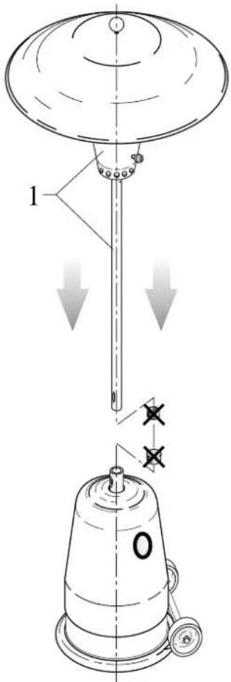
B: Fig.4 = parabolic hood (NOMAD and FIX)
B1: Fig.4 = parabolic hood and tubes (SPIDER)
C: Fig.5 = pole + burner and fixing knob for the hood (models NOMAD and FIX)
C1: Fig.5 = flanged support + burner and fixing knob, set of 2 diaphragms, umbraco spanner and instruction notice (model SPIDER)
IMPORTANT! DO NOT PROCEED WITH THE ASSEMBLY IF ONE OF THE PARTS IS DAMAGED!
IMPORTANT! In the MOBILE appliances (NOMAD), check whether the supplied hose connection meets the regulations in force in the country where it will be used, before making the connection.
2.1 STEP-BY-STEP ASSEMBLY type "NOMAD" (MOBILE type with LPG cylinder):
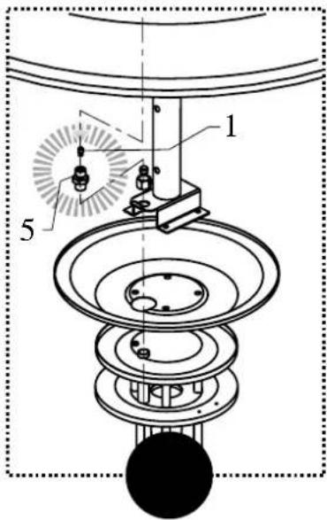
IMPORTANT! Before assembling the appliance, check whether its parts are appropriate for use in combination with the gas type and the gas pressure foreseen and whether they meet the regulations in force. Before assembling the heater, remove the two protection plugs (1: Fig.3A and 5: Fig.5). Make sure you do not lose them (they serve as protection when the heater needs to be dismantled).
IMPORTANT! In compliance with the regulations of the EC Certification, the “INFRA NOMAD CLASSIC” or “INFRA FIX CLASSIC” label shall be apposed in column C of the identification plate of the appliance at the inside of the clock that is mounted on the pole + burner (see drawing fig. A2).
1 – Put the "base plate + the structure" on the ground and remove the bell-shaped cylinder protection (2: Fig.3A) in order to facilitate the next steps of the assembly.
2 – Fix the upper, “adjustable” part of the A-shaped structure (1: Fig.6A and 6B) to the “fixed” part of the base plate at the desired height (“low” gas cylinder, A: Fig.6 or "high" gas cylinder, B: Fig.6 and Fig. 13), using the 4 nuts and screws supplied together with the structure (2: Fig.6A and 6B).
3 - Put the gas cylinder on the base plate and fasten it by inserting the belt (supplied) in the openings of the A-shaped structure and by winding it around the handles of the gas cylinder (Fig.7).
4 – Install the pressure regulator (NOT supplied, 2: Fig.8A and 6: Fig.5)) on the gas cylinder in accordance with the plates TECHNICAL DATA AND GAS TYPE on the appliance.
If the heater runs on butane or propane. The CE label on the heater indicates which type of gas can be used (G30 = butane; G31 = propane; G20 and G25 = natural gas). The tables 1 and 1b contain the appropriate gas pressures for each gas type and also indicate which type of pressure regulator must be used in each country.
5 – Buy a connection and a rubber connecting hose. Make sure their type and material are in conformity with the regulations of the country in which the heater is installed. (in case the supplied items should not fit).
To the threaded final part of the quickfit you can:
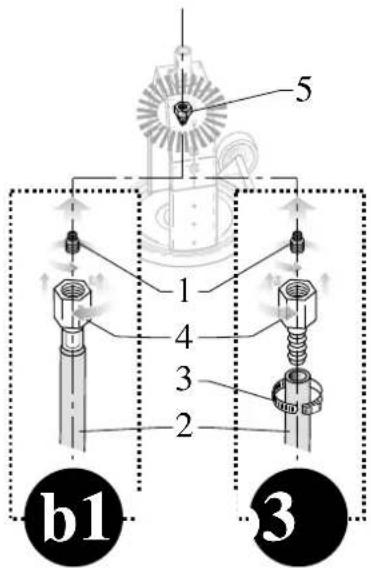
IN CASE A (B1: Fig.8): (1/4" gas turning to the left, 5: Fig.8) install the rubber hose (2) equipped with the appropriate threaded hose connection (4) (NOT SUPPLIED) (this solution is valid in the following countries: GERMANY, AUSTRIA, AND LUXEMBURG,
IN CASE B (B2: Fig.8): (1/4" gas turning to the right,, 5: Fig 8) fit the hose-end fitting (4) you have bought ((in case the supplied item should not fit)NOT SUPPLIED) directly to the threaded connection of the final part of the quickfit. Then fit the rubber hose (2) using the appropriate clip (3). ) (maximum length = 1,5 m).
IMPORTANT! Always make sure the rubber hose and the connection you have bought, are in conformity with the regulations that are in force in the country in which the heater is installed.
6 – Fix the bottom part of the connecting hose to the pressure regulator on the gas cylinder (3: Fig.8A). Connect the other end of the hose to the "quickfit" (3: Fig.8B) (already installed on the A-shaped structure) (NOT supplied, B1 and B2: Fig.8).
7 – Before you make the connection, check, by means of Table 1, whether it is necessary to install the gas diaphragm (supplied) (1: Fig.8B) on the inlet connection of the "quickfit" (only necessary in AUSTRIA and GERMANY).
8 – Take hold of the "pole + burner" and insert them in the quickfit on the base by pushing them slightly downwards (1: Fig.9A) until you hear a click.
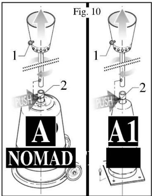
NOTE: To dismantle the heater, turn the pole of the burner until the ignition knob (1: Fig.10A-1) coincides with the release button (2: Fig.10A-1) of the quickfit on the base. Release the pole by pushing the round button. Lift the pole using both hands.
9 – Slightly tilt the heater to the side equipped with the wheels, put the parabolic hood (2: Fig.11) on top of the burner (3: Fig.11) and fix it immediately by means of the round knob (1: Fig.11). Finally put the heater in its vertical position.
IMPORTANT! The area, in which the heat generator will be used, must have a volume of at least 20 m³ per kW nominal power and must be well ventilated. If you want to use the INFRA at its maximum power, you must consequently have a volume of approximately 150 m³ for a INFRA Classic model, and a volume of 300 m³ for a INFRA Performant model.
IMPORTANT! ALWAYS insert the appropriate protection plug (5: Fig.5) before putting the quickfit of the "pole + burner" on the ground. This way you will avoid damaging the seals or obstructing the gas tubes.
IMPORTANT! It is strictly forbidden to MAKE ALTERATIONS to the heater, except in the cases provided for by the manufacturer (for example transformation gas).
2.2 STEP-BY-STEP ASSEMBLY type "FIX" (FIXED type for floor or ground fixing - using gas containers or gas network):
IMPORTANT! Before assembling the appliance, check whether its parts are appropriate for use in combination with the gas type and the gas pressure foreseen and whether they meet the regulations in force.
In case you should want to use the appliance with LPG 50 mbar (Germany, Austria and Luxemburg) you must install the diaphragm that fits the model (CLASSIC or PERFORMANT). The installation is represented in fig.8 and explained in the instructions you find in the set of diaphragms, on the type shield of the appliance and in tables 1a or 1c.
Before assembling the heater, remove the two protection plugs (1: Fig.3A and 5: Fig.5). Make sure you do not lose them (they serve as protection when the heater needs to be dismantled).
1 – Put the "base plate + the structure" on the ground and remove the bell-shaped gas inlet tube protection (2: Fig.3A1) and indicate the position of the 6 fixing holes on the ground (1: Fig. 6C).
2 - Centre the "base plate + the structure" with respect to the gas inlet tube (2: Fig.6C).
3 - Fix the structure to the ground using the 6 fastening screws supplied together with the structure (1: Fig.6C).
4 – Check whether the gas type and gas pressure match the ones mentioned on the identification plate (see Table 1). If necessary, install the pressure regulator/ reducer (NOT supplied, 2: Fig.8A).
5 - Buy a connection and a rubber connecting hose. Make sure their type and material are in conformity with the regulations of the country in which the heater is installed.
The threaded final part of the quickfit (1/4" gas turning to the right) can: by means of a rigid or flexible metal tubing be connected directly to a connection as foreseen in:
CASE A (B1: Fig.8): Install the rubber tubing (2) equipped with the appropriate threaded connection (4) (NOT SUPPLIED).
CASE B (B2: Fig.8): Screw the bought tubing connection (4) (in case the supplied connection should not be appropriate) directly to the threaded final part of the quickfit (1/4" gas) and subsequently fit the rubber hose (2) (maximum length = 1,5 m) by means of an appropriate bracket (3).
The treaded final part of the quickfit (1/4" gas turning to the right, 5: Fig.8) can, after having assembled the transition piece (1/4" gas turning to the right-turning to the left 6/ Fig.8), be connected to a flexible tubing as foreseen in:
IMPORTANT: Always make sure the rubber hose and the connection you have bought, are in conformity with the regulations that are in force in the country in which the heater is installed.
6 - Fix the gas inlet tube to the bottom part of the "quickfit" (already installed on the A-shaped structure).
7 – Check, before making the connection, by means of Table 1 and/or (1: Fig.8B and 6: Fig.5) whether it is necessary to install the gas diaphragm on the supply opening of the "quick coupling" (only necessary for LPG in AUSTRIA, GERMANY and Luxemburg).
8 – Put the parabolic hood (2: Fig.11) on top of the burner (3: Fig.11) and fix it immediately by means of the round knob (1: Fig.11).
9 – Take hold of the "pole + burner" and insert them in the quickfit on the base by pushing them slightly downwards (1: Fig.9A1) until you hear a click.
NOTE: To dismantle the heater, turn the pole of the burner until the ignition knob (1: Fig.10A-A1) coincides with the release button (2: Fig.10A-A1) of the quickfit on the base. Release the pole by pushing the round button. Lift the pole using both hands.
IMPORTANT! The area, in which the heat generator will be used, must have a volume of at least 20
m^3 per kW nominal power and must be well ventilated. If you want to use the INFRA at its maximum power, you must consequently have a volume of approximately 150 m^3 for a INFRA Classic model, and a volume of 300 m^3 for a INFRA Performant model.
IMPORTANT! ALWAYS insert the appropriate protection plug (5: Fig.5) before putting the quickfit of the "pole + burner" on the ground. This way you will avoid damaging the seals or obstructing the gas tubes.
IMPORTANT! It is strictly forbidden to MAKE ALTERATIONS to the heater, except in the cases provided for by the manufacturer (for example transformation gas).
2.3 STEP-BY-STEP ASSEMBLY type "SPIDER" (fixed type for wall or ceiling-installation with LPG gas cylinders or gas network)
IMPORTANT! Before assembling the appliance, check whether its parts are appropriate for use in combination with the gas type and the gas pressure foreseen and whether they meet the regulations in force. In case you should want to use the appliance in combination with liquid petroleum gas.
(LPG), you must install the diaphragm that fits the model (CLASSIC or PERFORMANT). The installation is represented in fig.8 and explained in the instructions you find in the set of diaphragms, on the type shield of the appliance and in tables 1a or 1c.
Remove the protective hood (4: Fig.9-A2) before the assembly. Make your you do not lose it (you will need it as protective hood when the appliance shall have to be disassembled again).
1 – Put the flange against the wall or the ceiling and mark the spots of the 4 fixing holes (1: Fig. 6D). Make the holes and insert the plugs.
2 - Fix the flange by means of the 4 supplied plugs (1: Fig.9-A2).
Attention : check whether the wall or the ceiling are fit to hang the appliance on the wall or to suspend it from the ceiling with the supplied plugs. In case the wall or ceiling should not be strong enough to install the Spider, the wall or the ceiling must be reinforced.
3 – Put the parabolic hood on the burner group (3:Fig 9-A2) and immediately fix it with the 4 supplied screws. Install and fix, if foreseen, the elongation pieces of the bracket or the support, after having adapted them to the required length, if so desired. Use the supplied fixing elements for the installation (2:Fig. 9-A2).
4 – Install the parabolic hood (2: Fig.11) on the burner (3: Fig. 11) and immediately fix it with the supplied round knob (1: Fig.11).
5 – If the appliance is equipped to run on LPG 50 mbar, (1: Fig.8-B3) install the supplied diaphragm corresponding to the value indicated in table 1C (see Tab. 2, Fig. 16).
6 - Connect the inlet coupling piece to the gas supply tubing. The upper threaded final part (1/4" gas turning to the right, 5: Fig.8-B3) can be connected directly to a rigid metal tubing.
7 – Check whether the type of gas and/or the gas pressure correspond to the type and pressure mentioned on the label (see Tab. 1). If so desired, install the pressure regulator/ pressure reducer (NOT supplied, 2: Fig.8A).
8 – Buy a connection and a connection hose that meet the type and material regulations in force in the country in which the appliance will be installed.
IMPORTANT! The area, in which the heat generator will be used, must have a volume of at least 20 m³ per kW nominal power and must be well ventilated. If you want to use the INFRA at its maximum power, you must consequently have a volume of approximately 150 m³ for a INFRA Classic model, and a volume of 300 m³ for a INFRA Performant model.
IMPORTANT! NEVER uncover the open end of the burner's connective piece and NEVER place it on the ground either. Protect it by means of the special protective hood (5: Fig.5) before making the connection. In that way, you avoid strange substances from penetrating into the appliance and from damaging the sealings or obstructing the gas supply.
IMPORTANT! It is strictly forbidden to make ALTERATIONS to the appliance, except in the cases provided for by the manufacturer.
2.4 – Installing the battery for the electronic ignition of the pilot flame:
- Remove the ignition/ adjustment knob (3: Fig.14).
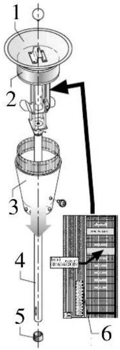
- Unscrew and lower the ring that supports the perforated bell (3: Fig.5) and that protects the burner's inner structure (1: Fig.14).
- Carefully lower the perforated bell + the steel cylinder.
- Find the battery holder (2: Fig.14). Unscrew the little cover and insert the 1.5V battery. Pay attention to the poles (Fig.14).
- Refit the cover and all the other parts you have previously removed.
3 - TURNING THE HEATER ON
IMPORTANT! Remove, the protective film, if any, of the plastic parts.
IMPORTANT! Before putting the appliance into operation, check whether the pressure regulator and/or the pressure relieve valve and the type of gas used correspond to the data in tables 1a and 1b and to the data on the identification plate of the appliance and so comply with the regulations that are in force in the country in which the appliance is used.
IMPORTANT! When using LPG cylinders, take into account the dimension of the cylinder recess (model NOMAD) (Fig.13).
DO NOT USE the heater in areas with combustible and/or explosive dust, gas damps, liquid fuels and inflammable material.
IMPORTANT! Repeated restarting: to avoid bursts of flame caused by gas accumulation, always wait 1 minute before restarting the heater.
IMPORTANT! ALWAYS fit the parabolic hood and the bell-shaped cylinder models NOMAD and FIX) before starting the heater. DO NOT cover the parts of the burner that emit heat completely or partially. DO NOT cover the heater shortly after turning it off. Wait until it has cooled down.
Put the heater on a flat surface to avoid it from turning over (slope < 10%). The surface must also be non-inflammable (wooden floor, linoleum, synthetic floor, etc).
IMPORTANT! DO NOT use the heater in basements if it is pre-set to run on LPG.
WHEN YOU TURN THE HEATER ON FOR THE FIRST TIME, AN OPERATION YOU SHOULD CARRY OUT OUTDOORS OR IN A WELL-VENTILATED ROOM, THE HEATER WILL EMIT FUMES FOR A SHORT PERIOD OF TIME.
IMPORTANT! Use soapy water or equivalent means to ensure that the tubings, the connections and the quickfit of the appliance (MODELS NOMAD and FIX) are LEAKPROOF. Also check the connec-
tions to the gas cylinder or the gas installation for leaks.
.
3.1 - Ignition
1 - Check whether the regulating knob is switched off (0: full point, Fig.15) and open the gas supply tap.
2 - Press the ignition knob and turn it anticlockwise (Fig.15). This way sparks are automatically discharged and gas is supplied for the ignition of the pilot. Once the pilot burns, you must continue to press the button for approximately 1 to 2 minutes (Fig.15) to allow the thermocouple to heat and to keep the valve open. Now you only have to adjust the burner's power (from MIN to MAX, Fig.15) according to your needs.
NOTE: when you turn the heater on for the first time, the pilot has the tendency to go out because of the air in the tubes. You must wait a bit longer for the flame to stabilise!
- If the pilot should accidentally go out, the incorporated safety device will automatically interrupt the gas supply.
- If the flame goes out for want of gas, the gas flow is interrupted (for example when the gas cylinder is empty).
- In both cases, you must wait a few minutes before restarting the heater. Then repeat the operations mentioned in points 1 and 2.
- Do not try to restart the heater time and again; if the heater does not work, you should check whether ALL operations have been carried out correctly.
IMPORTANT! WAIT A FEW MINUTES BETWEEN EACH RESTART TO AVOID THE ACCUMULATION OF GAS AROUND THE BURNER AS THIS MAY CAUSE SUDDEN BURSTS OF FLAME!
IMPORTANT! DO NOT TOUCH the burner or the hood while the burner is working or has only just been turned off as their temperature may cause burns. The heater can also be adjusted (MIN and MAX) when it is turned on. If the LPG-run heater is used outdoors and the temperature is below 2°C, we recommend the use of propane.
4 - TURNING THE HEATER OFF
1 - Turn the knob clockwise until it is on "0".
2 – Insert your hand in the lateral opening of the bell-shaped cylinder protection and turn off the gas tap.
IMPORTANT! IF YOU WILL NOT USE THE APPLIANCE FOR SOME TIME, REMOVE THE IGNITION BATTERY FROM ITS HOLDER TO AVOID CAUSTIC SUBSTANCES FROM LEAKING OUT OF THE BATTERY THUS DAMAGING THE APPLIANCE.
5 - MAINTENANCE
IMPORTANT! Regularly check with soapy water or equivalent means to ensure that the tubings, the connections and the quickfit of the appliance (MODELS NOMAD and FIX) are LEAKPROOF.
Also check the connections to the gas cylinder or the gas installation for leaks.
Before carrying out maintenance operations, make sure the gas tap and/or the knob of the burner are turned off.
- Maintenance comprises:
- Cleaning the outside of the heater (use a soft cloth and neutral detergents. Do not put any detergent straight onto the parts that require cleaning).
- Inspecting or replacing the rubber hose (Lmax=1.5m), when damaged and at the intervals and according to the methods provided for in the laws and regulations that are in force in the country in which the heater is installed.
- Checking whether the parts of the quick coupling are still intact and cleaning these parts. Only use original spare parts when replacing worn parts.
- Replacing the battery for the electronic ignition.
ALL other maintenance operations or alterations must be carried out by qualified fitters.
IMPORTANT! Regularly check the connections to the gas cylinder or the gas supply tube on leaks with a soap solution or a similar product.
5.1 REPLACING THE GAS JET (Only to be carried out by qualified fitters)
1 - Remove the ignition/ adjustment knob (1: Fig.12).
2 – Unscrew and lower the ring that supports the perforated bell that protects the burner's inner structure (2: Fig.12).
3 - Carefully lower the perforated bell + the steel cylinder.
4 – Find the gas jet (3: Fig. 12). Unscrew the gas jet from its housing under the venturi tube. Replace it. BE SURE NOT TO DAMAGE THE THREADED PARTS when tightening the gas jet.
5 – Refit the cover and all the other parts you have previously removed.
6 - TROUBLESHOOTING
IMPORTANT! Before carrying out repairs, always TURN OFF the gas tap.
If there is no flame when the heater is switched on, this can be caused by:
1 – an insufficient gas flow (bad LPG gasification or filth in the installation), a blocked or faulty pressure regulator.
2 - a sudden gust of wind (more than 3 m/ sec.).
3 - a lack of gas (empty gas cylinder or interrupted gas supply) or a faulty pressure regulator.
4 - an interrupted thermocouple.
5 - a faulty electromagnetic valve.
6 - filth in the gas circuit.
7 - gas leaks.
8 - an empty battery.
9 - insulation electrodes and/ or faulty cables.
7 - STORAGE
If you foresee that you will not use the heater for a while (change of season or another reason), store it in a dry place where it cannot get damaged (models NOMAD and FIX).
ALWAYS put the protection plugs on both parts of the quickfit and ALWAYS cover the burner and the base to avoid obstructions (cobwebs, dust) or damages (bruises, weather influences; etc.).
Model SPIDER: ALWAYS cover the burner with cloths (after that it cooled down completely) to avoid obstructions (cobwebs, dust) or damages (bruises, etc.).
IMPORTANT! Do not store one or more gas cylinders together with the heater. Gas cylinders should be stored outdoors, in conformity with the rules and regulations in force.
8 - Guarantee
The Barbecook® comes with a one year guarantee on production flaws, from the date of purchase and to the extent the use corresponds with the present instructions for use. The receipt mentioning the date of purchase counts as guarantee card.
This Barbecook® is not suited for professional use.
Wear, corrosion, deformation and discoloration (especially of the stainless steel) of the parts that are directly exposed to the fire is quite normal and will therefore in no event ever be considered as a production flaw: it is the logical result of their use.
Moreover, it is quite normal that the irongrid and the worn parts have to be replaced after a long period of use.
- BARBECOOK INFRÂ - - PT -
Índice
- Barbecook INFR - - NO -
innhold
- GENERELL BESKRIVELSE side 79
- MONTERING side 80
- START side 84
- SLUKKING side 85
- VEDLIKEHOLD side 85
- PROBLEMER side 86
- OPPBEVARING side 86
- GARANTI side 87