
DD 9663 - Range hood AEG-ELECTROLUX - Free user manual and instructions
Find the device manual for free DD 9663 AEG-ELECTROLUX in PDF.
| Product type | Built-in flat visor hood |
| Brand | AEG-Electrolux |
| Model | DD 9663 |
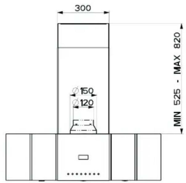
| Width (mm) | 900 |
| Minimum distance from cooking surface (mm) | 650 |
| Power supply | 220-240 V ~ 50 Hz |
| Motor power (W) | 200 |
| Lighting | 1 x halogen 20 W |
| Suction speeds | 3 + intensive (5 min) |
| Automatic shut-off | Yes (10 / 15 / 30 min according to speed) |
| Air outlet diameter (mm) | 150 / 120 |
| Grease filters | Metal, dishwasher safe |
| Activated carbon filter | Optional, replaceable every 4 months |
| Approximate weight (kg) | 12 |
| Controls | Touch controls with LED |
| Key lock | Yes (long press on button G) |
| Filter saturation alarm | Yes, adjustable for activated carbon |
| Noise level (dB) | Not specified |
Frequently Asked Questions - DD 9663 AEG-ELECTROLUX
User questions about DD 9663 AEG-ELECTROLUX
0 question about this device. Answer the ones you know or ask your own.
Ask a new question about this device
Download the instructions for your Range hood in PDF format for free! Find your manual DD 9663 - AEG-ELECTROLUX and take your electronic device back in hand. On this page are published all the documents necessary for the use of your device. DD 9663 by AEG-ELECTROLUX.
USER MANUAL DD 9663 AEG-ELECTROLUX
Built-In- Flat-Screen Fume Extractor Hood
Installation and Operating Instructions
Instructions Manual INDEX
RECOMMENDATIONS AND SUGGESTIONS 18
CHARACTERISTICS 19
INSTALLATION 21
USE 24
MAINTENANCE 25
RECOMMENDATIONS AND SUGGESTIONS
The Instructions for Use apply to several versions of this appliance. Accidingly, you may find descriptions of individual features that do not apply to your specific appliance.
INSTALLATION
- The manufacturer will not be held liable for any damages resulting from incorrect or improper installation.
- The minimum safety distance between the cooker top and the extractor hood is 650~mm .
- Check that the mains voltage corresponds to that indicated on the rating plate fixed to the inside of the hood.
- For Class I appliances, check that the domestic power supply guarantees adequate earthing.
Connect the extractor to the exhaust flue through a pipe of minimum diameter 120mm . The route of the flue must be as short as possible.
- Do not connect the extractor hood to exhaust ducts carrying combustion fumes (boilers, fireplaces, etc.).
- If the extractor is used in conjunction with non-electrical appliances (e.g. gas burning appliances), a sufficient degree of aeration must be guaranteed in the room in order to prevent the backflow of exhaust gas. The kitchen must have an opening communicating directly with the open air in order to guarantee the entry of clean air.
USE
- The extractor hood has been designed exclusively for domestic use to eliminate kitchen smells.
- Never use the hood for purposes other than for which it has been designed.
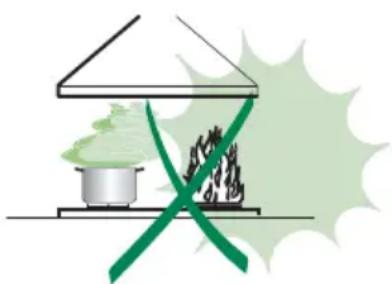
- Never leave high naked flames under the hood when it is in operation.
- Adjust the flame intensity to direct it onto the bottom of the pan only, making sure that it does not engulf the sides.
- Deep fat fryers must be continuously monitored during use: overheated oil can burst into flames.
- Do not flambe under the range hood; risk of fire
- This appliance is not intended for use by persons (including children) with reduced physical, sensory or mental capabilities, or lack of experience and knowledge, unless they have been given supervision or instruction concerning use of the appliance by a person responsible for their safety.
- Children should be supervised to ensure that they do not play with the appliance.
MAINTENANCE
- Switch off or unplug the appliance from the mains supply before carrying out any maintenance work.
- Clean and/or replace the Filters after the specified time period.
- Clean the hood using a damp cloth and a neutral liquid detergent.
The symbol on the product or on its packaging indicates that this product may not be treated as household waste. Instead it shall be handed over to the applicable collection point for the recycling of electrical and electronic equipment. By ensuring this product is disposed of correctly, you will help prevent potential negative consequences for the environment and human health, which could otherwise be caused by inappropriate waste handling of this product. For more detailed information about recycling of this product, please contact your local city office, your household waste disposal service or the shop where you purchased the product.
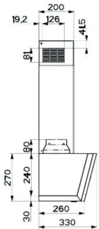
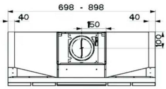
CHARACTERISTICS
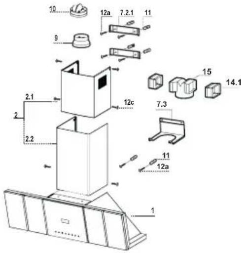
Components
Ref. Q.ty Product Components
1 1 Hood Body, complete with: Controls, Light, Blower, Filters
2 1 Telescopic Chimney comprising:
2.1 1 Upper Section
2.2 1 Lower Section
9 1 Reducer Flange 150-120 mm
10 1 Damper 0 150
14.1 2 Air Outlet Connection Extension
15 1 Air Outlet Connection
Ref. Q.ty Installation Components
7.2.1 2 Upper Chimney Section Fixing Brackets
7.3 1 Air Outlet Connection Support
11 6 Wall Plugs
12a 6 Screws 4,2 x 44,4
12c 6 Screws 2,9 x 9,5
Q.ty Documentation
1 Instruction Manual
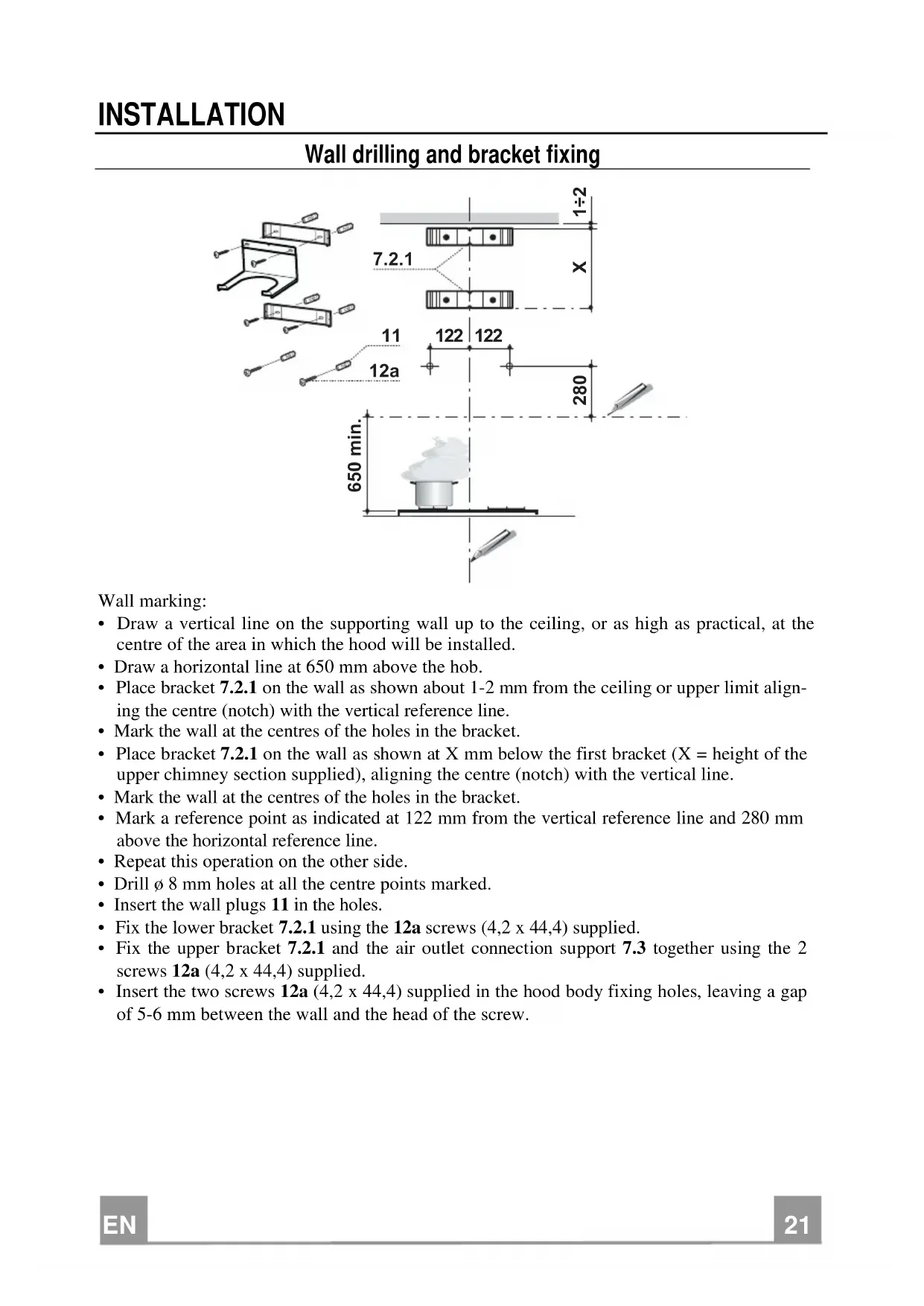
Wall drilling and bracket fixing
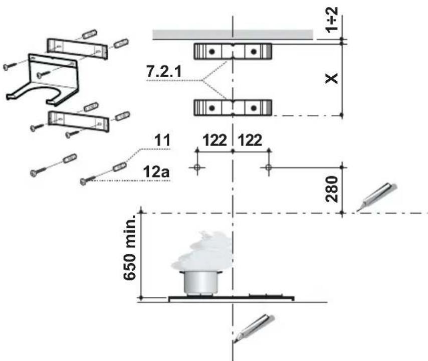
Wall marking:
- Draw a vertical line on the supporting wall up to the ceiling, or as high as practical, at the centre of the area in which the hood will be installed.
- Draw a horizontal line at 650mm above the hob.
- Place bracket 7.2.1 on the wall as shown about 1 - 2mm from the ceiling or upper limit aligning the centre (notch) with the vertical reference line.
- Mark the wall at the centres of the holes in the bracket.
- Place bracket 7.2.1 on the wall as shown at X mm below the first bracket ( X = height of the upper chimney section supplied), aligning the centre (notch) with the vertical line.
- Mark the wall at the centres of the holes in the bracket.
- Mark a reference point as indicated at 122mm from the vertical reference line and 280mm above the horizontal reference line.
- Repeat this operation on the other side.
- Drill 8mm holes at all the centre points marked.
- Insert the wall plugs 11 in the holes.
Fix the lower bracket 7.2.1 using the 12a screws (4,2× 44,4) supplied.
Fix the upper bracket 7.2.1 and the air outlet connection support 7.3 together using the 2 screws 12a (4,2 x 44,4) supplied. - Insert the two screws 12a (4,2 x 44,4) supplied in the hood body fixing holes, leaving a gap of 5 - 6mm between the wall and the head of the screw.
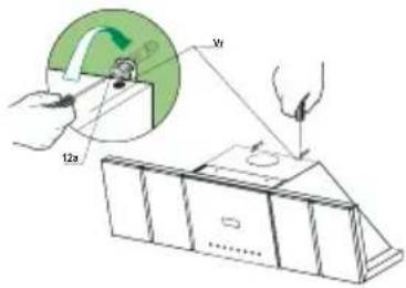
Mounting the hood body
- Before attaching the hood body, tighten the two screws Vr located on the hood body mounting points.
- Hook the hood body onto the screws 12a.
- Fully tighten support screws 12a.
- Adjust screws Vr to level the hood body.
Connections
DUCTED VERSION AIR EXHAUST SYSTEM
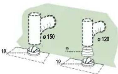
When installing the ducted version, connect the hood to the chimney using either a flexible or rigid pipe 150 or 120mm the choice of which is left to the installer.
To install a 0 150
To install the dumper 10
Fix the pipe in position using sufficient pipe clamps (not supplied).
To install a 0 120
- To install a 120mm air exhaust connection, insert the reducer flange 9 on the dumper 10.
Fix the pipe in position using sufficient pipe clamps (not supplied). - Remove any activated charcoal filters.
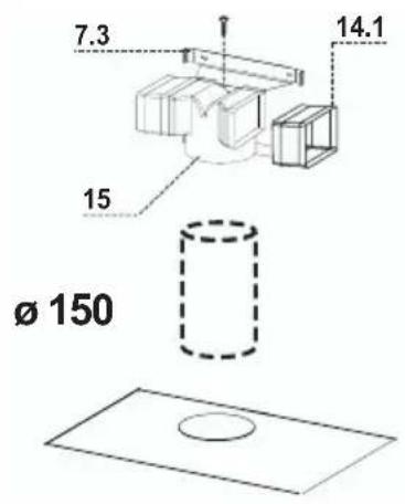
RECIRCULATION VERSION AIR OUTLET
- Insert the connection extension pieces laterally 14.1 in connection 15
- Insert the Connector 15 into the Support bracket 7.3 and fix it with a screw.
- Make sure that the outlet of the extension pieces 14.1 is horizontally aligned with the chimney outlets.
- Connect the air outlet connection 15 to the hood body outlet using either a flexible or rigid pipe 150mm , the choice of which is left to the installer.
- Ensure that the activated charcoal filters have been inserted.
ELECTRICAL CONNECTION
- Connect the hood to the mains through a two-pole switch having a contact gap of at least 3mm .
- Remove the grease filters (see paragraph Maintenance) being sure that the connector of the feeding cable is correctly inserted in the socket placed on the side of the fan.
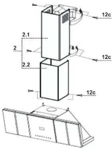
Flue assembly
Upper exhaust flue
- Slightly widen the two sides of the upper flue and hook them behind the brackets 7.2.1, making sure that they are well seated.
- Secure the sides to the brackets using the 4 screws 12c (2,9 x 9,5) supplied.
- Make sure that the outlet of the extensions pieces is aligned with the chimney outlets.
Lower exhaust flue
- Slightly widen the two sides of the flue and hook them between the upper flue and the wall, making sure that they are well seated.
Fix the lower part laterally to the hood body using the 2 screws 12c (2,9× 9,5) supplied.
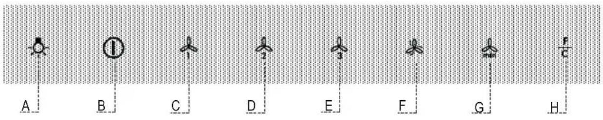
Control panel
| Button | Function Led | |
| A Turns the Lighting System on and off. On or Off. | ||
| B Turns the Motor on and off. On or Off | ||
| C Activates speed one. On. | ||
| D Activates speed two. On. | ||
| E Activates speed three. On. | ||
| F Activates intensive speed from any other speed, including motor off. This speed is timed to run for 5 minutes, after which the system will return to the speed that was previously set. Suitable to deal with severe cooking fumes.It is deactivated by pressing the button or turning the motor off. | On. | |
| G Activates delayed automatic shutdown of the motor and the lighting system after 10' if speed three is set, after 15' if speed two is set, and after 30' if speed one is set.Suitable to complete the elimination of residual odours, it is deactivated by pressing the button of turning the motor off.Enables Keyboard Lock mode if pressed and held for 5 seconds.It is disabled by pressing the button for 5 seconds. | On.All the Leds flash twice and during Keyboard Lock the Leds light up in sequence.All the Leds flash once. | |
| H Perform a Reset of the Filter saturation alarm when the button is pressed for approximately 2 seconds with the hood turned off.If pressed and held for 5 seconds with the hood turned off, it:enables the Activated Charcoal Filter Alarm.disables the Activated Charcoal Filter Alarm. | After 100 hours operation the Led lights up continuously to indicate saturation of the Metal Grease Filters.After 200 hours operation the Led flashes to indicate saturation of the Activated Charcoal Filters.2 Flashes1 Flash | |
Metal grease filters
CLEANING THE SELF-BEARING METAL GREASE FILTERS
Resetting the alarm signal
- Turn the Lights and the Suction motor off.
- Press button H and hold for at least 2 seconds, confirmation is provided by the fact that the Led goes out.
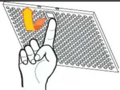
Cleaning the Filters
- These filters can be washed in a dishwasher, and need to be cleaned when the Led on Button H lights up in a continuous manner or at least once every approximately two months' use, or more frequently in the case of particularly intensive use.
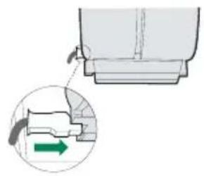
- Remove the Filters one at a time, supporting them with one hand while you pull the lever down with the other.
- Wash the Filters without bending them, and leave them to dry before replacing them.
- Replace the filters, taking care to ensure that the handle is facing outwards.
Activated charcoal filters (Recirculation Version)
This filter cannot be washed or regenerated, and must be replaced when the Led on Button H starts to flash, or at least every 4 months. The alarm can only be seen when the Suction motor is turned on.
Enabling the alarm signal
- For Recirculation Version Hoods, the Filter saturation alarm must be enabled on installation or at a later date.
- Turn the Lights and the Suction motor off.
-
Press button H and hold for at least 5 seconds until the Led gives confirmation as follows:
-
Led flashes twice - Activated Charcoal Filter Alarm ENABLED.
- Led flashes once - Activated Charcoal Filter Alarm DISABLED.
Changing the Activated Charcoal Filter
Resetting the alarm signal
- Turn the Lights and the Suction motor off.
- Press button H and hold for at least 2 seconds, confirmation is provided by the fact that the Led goes out.
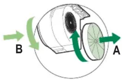
Changing the Filter
- Open the glass panel on the hood by pulling downwards.
- Remove the saturated activated charcoal filters as shown (A).
- Fit the new filters, as indicated (B).
- Close the glass panel.
Lighting
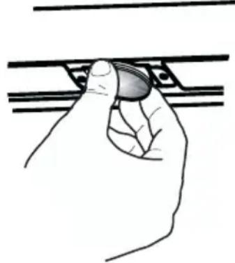
LIGHT REPLACEMENT
20 W halogen light.
- Extract the lamp from the lamp holder by pulling gently.
- Replace with another of the same type, making sure that the two pins are properly inserted in the lamp holder socket holes.
ADVIEZEN EN SUGGESTIES
REEMPLACEMENT LAMPES


- Instructions Manual INDEX
- RECOMMENDATIONS AND SUGGESTIONS
- INSTALLATION
- USE
- MAINTENANCE
- CHARACTERISTICS
- Components
- Wall drilling and bracket fixing
- Wall marking:
- Mounting the hood body
- Connections
- DUCTED VERSION AIR EXHAUST SYSTEM
- To install a 0 150
- To install a 0 120
- RECIRCULATION VERSION AIR OUTLET
- ELECTRICAL CONNECTION
- Flue assembly
- Upper exhaust flue
- Lower exhaust flue
- Metal grease filters
- CLEANING THE SELF-BEARING METAL GREASE FILTERS
- Resetting the alarm signal
- Cleaning the Filters
- Activated charcoal filters (Recirculation Version)
- Enabling the alarm signal
- Changing the Activated Charcoal Filter
- Changing the Filter
- Lighting
- LIGHT REPLACEMENT
- W halogen light.
- ADVIEZEN EN SUGGESTIES
- REEMPLACEMENT LAMPES
Brand : AEG-ELECTROLUX
Model : DD 9663
Category : Range hood