Argus 300 - Motion detector Merten - Free user manual and instructions
Find the device manual for free Argus 300 Merten in PDF.
| Product type | Motion detector |
| Brand | Merten |
| Model | Argus 300 |
| Power supply | 230 V AC ±10%, 50 Hz |
| Max. switching current | 16 A, cos φ = 0.6 |
| Rated power (incandescent lamps) | 3000 W |
| Rated power (halogen lamps) | 2500 W |
| Rated power (fluorescent) | 1200 W (uncompensated) |
| Power consumption | < 1 W |
| Indoor detection zone | 360°, radius 4 m |
| Medium detection zone | 300°, radius 7 m |
| Outdoor detection zone | 300°, field 16 m x 20 m |
| Max. range | 16 m |
| Mounting height | 2 m to 3 m (optimal 2.5 m) |
| Sensitivity | Continuously adjustable |
| Brightness threshold | Adjustable from 3 to 1000 lux |
| Switch-on time | Adjustable from 1 s to 8 min |
| Protection rating | IP 55 |
| Connection terminals | For conductors 1.5 or 2.5 mm² |
| Extension possible | Yes (ref. 554395/554399) |
| Zone masking | Masking segments (60°) |
| Cleaning | Clean the lens with a soft dry cloth |
| Safety | Installation by a qualified electrician, compliance with standards |
Frequently Asked Questions - Argus 300 Merten
User questions about Argus 300 Merten
0 question about this device. Answer the ones you know or ask your own.
Ask a new question about this device
Download the instructions for your Motion detector in PDF format for free! Find your manual Argus 300 - Merten and take your electronic device back in hand. On this page are published all the documents necessary for the use of your device. Argus 300 by Merten.
USER MANUAL Argus 300 Merten
D GB NL E F I S

Operating instructions 12
What you can do with the ARGUS 300
What you can do with the ARGUS 300
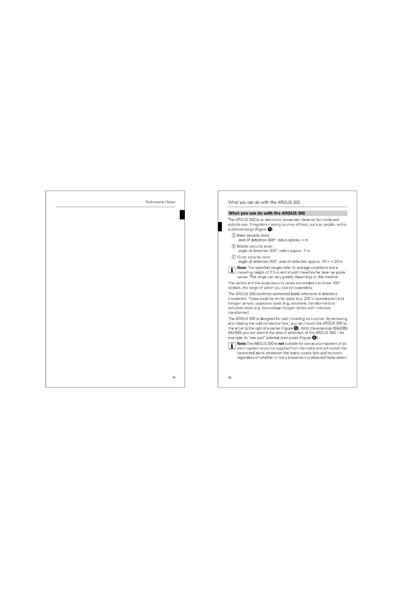
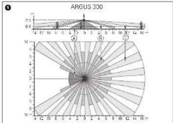
The ARGUS 300 is an electronic movement detector for inside and outside use. It registers moving sources of heat, such as people, within a defined range (Figure 1):
Inner security zone: area of detection 360^ , radius approx. 4 m.
Middle security zone
angle of detection 300^ radius approx.7 m
Outer security zone
angle of detection 300^ area of detection approx. 16m× 20m

Note: The specified ranges refer to average conditions and a mounting height of 2.5m and should therefore be taken as guide values. The range can vary greatly depending on the weather.
The central and the outer security zones are divided into three 100^ sectors, the range of which you can set separately.
The ARGUS 300 switches connected loads whenever it detects a movement. These could be ohmic loads (e.g. 230V incandescent and halogen lamps, capacitive loads (e.g. electronic transformers) or inductive loads (e.g. low-voltage halogen lamps with inductive transformer).
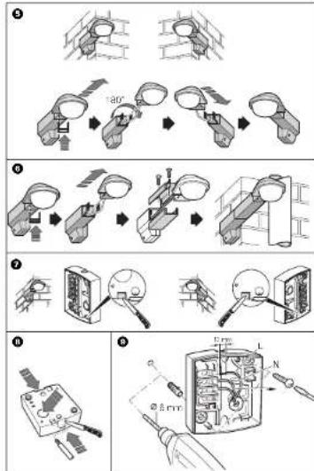
The ARGUS 300 is designed for wall mounting on a corner. By removing and rotating the wall connection box, you can mount the ARGUS 300 to the left or to the right of a corner (Figure 6). With the extension (554395/554399) you can extend the area of detection of the ARGUS 300 – for example, to 'see past' external drain pipes (Figure 6).
Note:The ARGUS 300 is not suitable for use as a component of an alarm system since it is supplied from the mains and will switch the connected alarm whenever the mains supply fails and recovers, regardless of whether or not a movement is detected (false alarm).
12
How to choose an installation site
How to choose an installation site
Figure 2
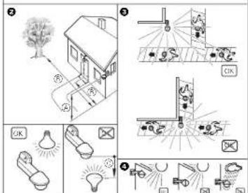
Mounting height: between 2 m and 3 m, optimal is 2.5 m on a solid and flat surface.
Distance from sources of optical interference: approx. 5-6 m
If the luminaire to be switched is located within the area of detection of the ARGUS 300, there should be a distance of at least 5m between the ARGUS and the light. Mount the luminaire above the ARGUS, not below it. Otherwise, use the segments provided to shade it (see the section "How to mask individual areas").
For optimum movement detection, mount the ARGUS 300 sideways to the direction of motion (Figure 5).
The ARGUS 300 is in protection class IP 55 and is therefore also suitable for outdoor use. To make sure that the lighting is not switched on by environmental influences, you should ensure that the ARGUS 300 is sheltered from rain and direct sunlight (for example, raindrops running down the lens could cause the movement detector to be switched) (Figure 4).
Further information can be found in the 'Merten Technical Information', in the section 'ARGUS movement detector'.
How to mount the ARGUS 300
Risk of electrocution
The ARGUS may only be installed and connected by skilled electricians. Please observe the relevant regulations in your own country.
Caution: If installation is not carried out correctly, water can penetrate into the ARGUS and damage it. Always mount the ARGUS with the spherical head pointing downwards.
13
How to mount the ARGUS 300
To rotate the wall connection box:
The ARGUS 300 is supplied ready for mounting on the wall to the left of a corner. To mount on a wall to the right of a corner (Figure ①):
Press in the u-shaped release clip directly behind the sensor head from underneath until it reaches the stop in both openings.
② Remove the sensor head.
Rotate the wall bracket by 180^ and then put the sensor head back on.
To install the extension (554395/554399):
Figure 6:
Press in the u-shaped release clip directly behind the sensor head from underneath until it reaches the stop in both openings.
② Remove the sensor head.
③ Place the two halves of the extension around the connection cable, so that the screws are at the top. Then screw them together.
Refit the sensor head.
To open the hole for condensation water:
Depending on whether it is installed to the left or right of a corner, you must open the lower of the two openings in the wall connection box (Figure ①):
Use a knife to cut open the rubberised condensation water opening from behind.
See also the sticker inside the wall connection box.
Fitting the connection cable:
You can feed the connection cable from behind, from below or from above, into the wall connection box:
Cut out the rubberised cable entry as required with a knife (Figure 6).
Feed in the connection cable and mount the wall connection box (Figure 0).
14
How to install the electrical connection
How to install the electrical connection
Figure 9
① Strip 13 mm of the connecting cable insulation.
(2) Insert the live conductor into terminal "L"
Insert the neutral conductor into terminal N
Insert the switched live conductor into terminal
'Through-wiring' to other loads is permitted.
i Note When switching inductive loads such as transformers, relays, contactors or fluorescent lamps, spikes occur which could lead to the load being switched on again I maintained light effect). Connect a capacitor (542895) in parallel to the inductive load to reduce these spikes.
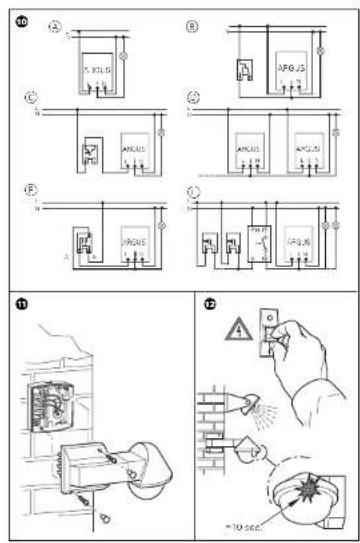
Installation options (Figure 10)
ARGUS constantly connected to the mains: ARGUS monitors its area constantly.
ARGUS combined with two-way switch: depending on the switch position, either maintained light or automatic mode.
ARGUS combined with break contact: ARGUS is always ready for operation. By pressing the push-button (the power is briefly disconnected for 2-3 seconds), the ARGUS is switched on for the set period. Every further movement increases the switching duration.
ARGUS in parallel: Several ARGUS devices can switch a lamp group provided the maximum switching capacity of one device is not exceeded. To achieve this, you must reduce the sensitivity of the devices. For technical and functional reasons, we do not advise using more than four ARGUS devices in one group.
15
How to put the ARGUS into operation
ARGUS combined with serial switch: depending on the switch position, either manual, automatic mode or OFF'. In position A, the luminaire is switched on by the ARGUS automatic and in position B, it is switched on continuously (manual).
ARGUS in parallel with a staircase timer: either the ARGUS or the staircase timer switches the luminaires on for a certain period.
Mounting the top section of the ARGUS:
Figure 11
Place the upper section of the ARGUS onto the connection box and fasten it using the two screws provided.
Note: Wait until you have made all the necessary settings before fitting caps to the screw openings, since removing them can cause damage.
How to put the ARGUS Into operation
Figure 12
Connect the supply voltage
The load is switched on for approx. 10 s or for the set period. The functional display lights up for approx. 10 s.
Using operating elements
All settings are made using the ARGUS 300 operating elements which are located under the protective cover of the sensor head. To open:
Pull the cap on the sensor head at an angle of 45^ about 1 cm diagonally upwards (Figure 19).
16
How to put the ARGUS into operation
ARGUS displays and operating elements:
Figure 14:
To set the sensitivity
To set the brightness threshold
To set the switching duration
Functional display: lights up whenever movement is detected
(Brightness sensor: must not be covered)
F1 Range of the front 100^ sector (side adjusters F2 and F3 see Figure
16)
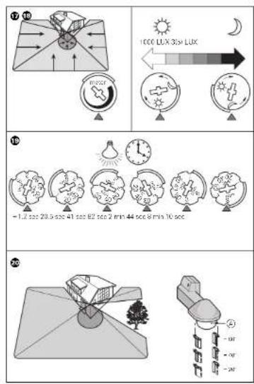
Setting the ARGUS for the function test:
Set the brightness threshold (Figure 10) to daytime operation (sun symbol/right-hand stop).
② Set the switching duration (Figure 14(c)) to 1 s (left-hand stop).
③ Set range adjusters F1, F2 and F3 to "max" ("max" at the top, "min" at the bottom).
Aligning the ARGUS:
① Figure 16. Align the sensor head with the area to be monitored (change the direction of rotation when you have turned it as far as the stop).
Step from the edge of the detection area into it (Figure 3) to check whether the ARGUS switches the load and the functional display as required.
Set the range of the 100^ sectors:
Using the adjusters F1, F2 and F3 (Figure 10) you can reduce the range of each sector from 100% ('max' at bottom) to 60% 'min' at bottom).
① Set the range.
17
How to put the ARGUS into operation
Setting the sensitivity:
Here (Figure 10) you can set the distance up to which ARGUS detects movements. I can be set continuously up to a maximum of 16m .
Set the sensitivity (Figure 1)
Setting the brightness threshold:
Here (Figure 16) you can continuously adjust the ambient brightness level at which movements should be detected and switching triggered.
Set the brightness threshold (Figure 18):
- Right stop (sun symbol): Day and night operation (approx. 1000 lux), all movements in the area of detection will be detected, independent of the external brightness.
- Left stop (moon symbol): Night operation (polar white: approx. 3 lux, dark blue: approx. 5 lux), movements are only detected in the dark.
Setting the switching duration:
Here (Figure 19) you can set how long the loads connected to the ARGUS remain switched on. When the ARGUS detects a movement, the load is switched on and stays switched on until the set period has elapsed. Every further movement restarts the switching duration.
Note: The ARGUS ignores the light-sensitive switch after the load has been switched on. If the movement detector does not switch off again, the reason is probably that the ARGUS has detected further movements and has restarted the switching duration several times.
Setting the switching duration (Figure 19).
- Left stop: switching duration approx. 1 s
-Right stop: switching duration approx. 8 min
18
How to mask individual areas
How to mask individual areas
If there are sources of interference in the area monitored by the ARGUS, e.g. trees, shrubs or light sources, and these accidentally trigger the switching of the load, you can mask these areas using the segments supplied (Figure 20). Each segment blocks an area of 60^ and can be broken off in 20^ sections.
Place the inserts exactly on those areas of the sensor head which should be masked from detection and press them firmly onto the sensor head from underneath.
Note:The twilight sensor 已 at the front must not be covered by segments, since this reduces the light sensitivity.
Technical data
Caution! Operation only possible with sinusoidal mains voltages. Phase control dimmers or inverters with square-wave or trapezoidal voltage curves will damage the device.
Mains voltage: AC 230 V ±10%, 50 Hz
Max. switching current: 16 A, AC 230 V, cos φ = 0.6
Nominal power:
Incandescent lamps
AC 230 V: max. 3000 W
Halogen Jamps AC 230 V; max. 2500 W
Fluorescent lamps
AC 230 V: max. 1200 W, uncompensated
Capacitive load: max. 140 F
Power consumption: < 1 W
Connecting terminals: for 2 × 1.5 ~mm or 2 × 2.5 ~mm rigid
conductors, snipped length 13 mm
External diameter of a
cable: max. 14.5 mm
Area of detection: 300^
19
Technical data
Range: max. 16 m
Number of levels: 7
Number of zones: 123 with 492 switching segments
Minimum mounting
height: 17 m
Recommended mounting
height:
Sensitivity: continuouslyadjustable
Light sensor continuouslyadjustable
564319:approx.3-1000lux
Switching duration:
Neutral conductor:
Possible settings for
sensor head:
Type of protection:
EC guidelines:
20
Technical data
21
Comment monter I'ARGUS 300?
Comment monter l'ARGUS 300?
Charge capacitive: max. 140 μ
directive CEM 89/336/CEE.
51
564319: circa 3-1000 Lux,
564315:circa 5-1000 Lux
Glodlampor 230V AC: max. 3000 W
Halogenlampor 230V AC: max. 2500 W
Halogenlampor 230V AC: max. 1200 W, okompenserat
Kapacitiv last: max. 140 uF
Kanslighat: Steglost instalbar