Cavalry - Binoculars CELESTRON - Free user manual and instructions
Find the device manual for free Cavalry CELESTRON in PDF.

Frequently Asked Questions - Cavalry CELESTRON
User questions about Cavalry CELESTRON
0 question about this device. Answer the ones you know or ask your own.
Ask a new question about this device
Download the instructions for your Binoculars in PDF format for free! Find your manual Cavalry - CELESTRON and take your electronic device back in hand. On this page are published all the documents necessary for the use of your device. Cavalry by CELESTRON.
USER MANUAL Cavalry CELESTRON
natural_image
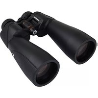
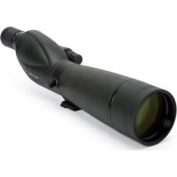
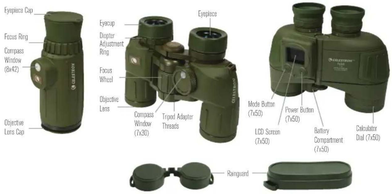
Collection of green CELESTRON binoculars with no visible text or symbols on the devices themselves.CAVALRY
BINOCULARS | JUMELLE
BINOCULARES | FERNGLAS
BINOCOLI
ENGLISH ....1
FRANÇAIS ......21
ESPAÑOL 41
DEUTSCH 61
ITALIANO....81
ENGLISH
CAVALRY
BINOCULARS
CELESTRON® CAVALRY BINOCULARS AND MONOCULAR
Thank you for purchasing a Celestron Cavalry binocular/monocular. We trust this binocular/monocular will provide you with years of enjoyment and faithful service. Please read the instructions carefully before using your binocular/monocular to ensure proper use and care.

WARNING: Viewing the Sun may cause permanent eye damage. Do not view the Sun with your binoculars/monocular or even with the naked eye.
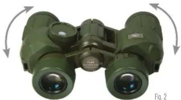
ADJUSTING THE INTERPUPILLARY DISTANCE (IPD)
The interpupillary distance, or the distance between the pupils, varies from person to person. The binocular must be correctly aligned (adjusted) to the distance between your pupils to achieve a single, clear image. To adjust this distance, lift the binocular up to your eyes (using both hands) and look through them at an object in the distance. Move the two barrels (halves) of the binocular closer together or further apart until you see a single, clear image (Fig. 2). Check that the interpupillary distance is set correctly every time you use your binocular.
natural_image
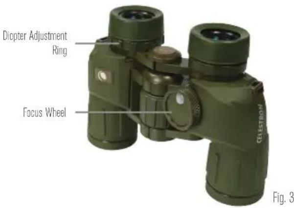
Green binoculars with directional arrows indicating rotational motion (no text or symbols on the device itself)SETTING THE DIOPTER / FOCUSING
Models 71420, 71424, and 71426
To ensure a crisp, sharp image the focusing system of the binocular must be set to compensate for any differences in your eyesight. This is achieved by setting the diopter (located on the right eyepiece) before use. To set the binocular to your eyesight follow the instructions below.
- View an object in the distance through the binocular.
- Cover the right objective lens with your hand or the objective lens cap.
- Rotate the focus wheel until the image viewed with your left eye is clear and sharp.
-
Cover the left objective lens with your hand or objective lens cap.
-
Viewing the same object, adjust the diopter ring until the image viewed with your right eye is clear and sharp.
- Your binocular is now adjusted to your eyes and focusing on any object can now be achieved by simply turning the focus wheel.
text_image
Diopter Adjustment Ring Focus Wheel Fig. 3Model 71422
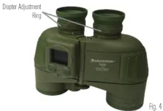
The Cavalry 7x50 utilizes an individual focus system which requires you to focus each eyepiece to ensure a crisp, sharp image. This is achieved by setting the diopter (located on each eyepiece) before use. Once the binocular is adjusted to your eyesight at a distance of approximately 100 yards, the binocular will be in focus without additional adjustment to an infinite distance (for distances closer than 100 yards readjustment may be necessary). To set the binocular to your eyesight follow the instructions below.
- View an object at a distance of 100 yards or more through the binocular.
- Cover the right objective lens with your hand or the objective lens cap.
-
Rotate the left eyepiece until the image viewed with your left eye is clear and sharp.
-
Cover the left objective lens with your hand or objective lens cap.
- Viewing the same object, rotate the right eyepiece until the image viewed with your right eye is clear and sharp.
- Your binocular is now adjusted to your eyes and refocusing is not necessary for objects at 100 yards or more. Adjustment may be needed for distances closer than 100 yards.
text_image
Diopter Adjustment Ring CRELESTION® 7-80 Fig. 4Model 71215
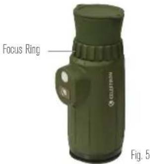
The focus of the Cavalry 8x42 monocular is adjusted by simply turning the focus ring located in front of the eyepiece.
Tip: Eyeglasses worn for nearsightedness should be worn when using a binocular/monocular as you may not be able to obtain focus at infinity without them.
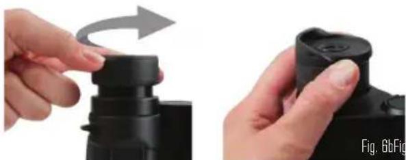
EYECUP ADJUSTMENT
The Cavalry models 71420 and 71424 feature twist-up eyecups and models 71422, 71426 and 71215 feature foldable rubber eyecups to accommodate both eyeglass and non-eyeglass wearers. If you do not wear eyeglasses, leave the rubber eyecups in the up position or twist the eyecups counterclockwise until they reach the up position. If you wear eyeglasses, make sure that the eyecups are in the down position to obtain the maximum field of view. The twist-up eyecups can be set at positions between
text_image
Focus Ring CLUTTER Fig. 5fully up and down which may suit some users better. When done observing, make sure the rubber eyecups are in the up position for storage.
natural_image
Two hands holding a black camera module, one with a curved arrow indicating rotation (no text or symbols visible)TRIPOD ADAPTABILITY
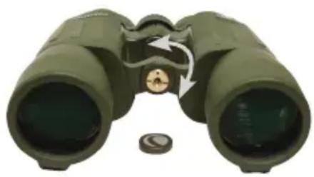
The Cavalry binoculars feature built-in threads that allow the binocular to be attached to a tripod using a binocular tripod adapter. These threads can be accessed by unscrewing the logo plate found on the front of the hinge (Fig. 7). To attach the binocular to a tripod, thread the adapter into the binocular and attach the other end of the adapter to a photographic tripod. Mounting the binocular on a tripod allows for added stability and comfort during prolonged viewing.
natural_image
Illustration of a green binoculars with an arrow indicating rotational motion (no text or symbols)Fig. 7
WATERPROOF / FOGPROOF
The Cavalry Series is waterproof and filled with dry nitrogen gas to prevent the housing from fogging internally.
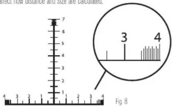
USING THE RETICLE
Cavalry models 71420, 71422 and 71215 have an integrated reticle that can be used to estimate size and distance. The reticle is divided into 10mil increments with 5mil marks between each 10mil increment. Each 10mil increment is indicated using single digit numbers (1, 2, 3, etc.). For finer ranging ability the last 5mils of the reticle are divided into 1mil and 0.5mil increments.
CALCULATING DISTANCE
Using the simple formulas below, you can effectively determine the distance to the target if its size is known.
$$ \frac {\text { Target Size (Yards) } \times 1 0 0 0}{\text { Measured Mils }} = \text { Range (Yards) } $$
Note: The reticle varies slightly from model to model but this does not affect how distance and size are calculated.
text_image
direct flow distance and size are calculated. 7 6 5 4 3 2 1 4 3 2 1 Fig. 8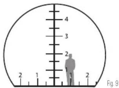
text_image
4 3 2 2 1 Fig. 9$$ \frac {\text { Target Size (Inches) } \times 2 7 . 8}{\text { Measured Mils }} = \text { Range (Yards) } $$
$$ \frac {\text { Target Size (Meters) } \times 1 0 0 0}{\text { Measured Mils }} = \text { Range (Meters) } $$
For example:
You range a 6-foot tall man (2 yards) that is 20mils tall and you want to know the distance to him.
$$ \frac {2 (\text { Yards }) \times 1 0 0 0}{2 0 \text { Mils }} = 1 0 0 \text { Yards } $$
USING THE CALCULATOR DIAL (MODEL 71422 ONLY)
The Calculator Dial located on the left objective barrel can be used to determine distance quickly and easily without using the formulas above. The calculator is composed of a triangular indicator marked "Angle", a rotating ring and three number scales. The first two scales are on the rotating ring; the first scale is the "Angle" measured in MILS and the second scale is the "Object Size". The third scale below the rotating ring is the "Distance" reading. To use the calculator, look through the binoculars and measure the height of an object using the reticle. Using the same example above, a man is seen that measures 20mils tall. Using the rotating ring, align the triangular indicator to the number 2 (20mils) on the Angle scale. Estimating that the man is 6 feet tall (2 yards), locate the number 2 on the "Object Size" scale. Each number on the "Object Size" scale will correspond to a number on the fixed distance scale. In this example the 2 on the distance scale is lined up with 100, so the man measured in the binocular is 100 yards away.
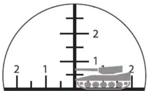
CALCULATING SIZE (HEIGHT AND WIDTH)
Using the simple formulas below, you can effectively determine the size of a target if the distance to the target is known.
$$ \frac {\text { Range (Yards) } \times \text { Measured Mills }}{1 0 0 0} = \text { Target size (Yards) } $$
$$ \frac {\text { Range (Yards) } \times \text { Measured Mils }}{2 7 8} = \text { Target size (Inches) } $$
$$ \frac {\text { Range (Meters) } \times \text { Measured Mils }}{1 0 0 0} = \text { Target size (Meters) } $$
text_image
2 1 2 1 2Fig. 10
For example:
You are 300 meters away from a tank that measures 15 miles tall and 20mils wide and you want to know the size of the tank.
$$ \frac {3 0 0 (\text { Meters }) \times 1 5 \text { Mils }}{1 0 0 0} = 4. 5 \text { Meters tall } $$
$$ \frac {3 0 0 (\text { Meters }) \times 2 0 \text { Mils }}{1 0 0 0} = 6 \text { Meters wide } $$
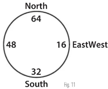
Models 71420, 71215
Models 71420 and 71215 have a built in 6400mil analog compass. The compass reading is aligned with the vertical line of the reticle and each hash mark of the compass represents 20 mils. The compass will only indicate direction to or from an object but not relative position. To determine position you need a map or chart and a protractor. When an object lies north from you, the compass will read 64 (6400mils). The mils will increase as you look through the binocular and scan clockwise. 16 (1600mils) means that the object lies east from you, 32 (3200mils) is south and 48 (4800mils) is west. To ensure precise measurements, make sure that the object is in the middle of the reticle and that the binocular is held horizontal and level when reading the compass.
Note: When using the compass always keep in mind the local variation between magnetic north (the compass reading) and true north. When holding the binocular make sure that your finger/hand is not covering the white button (compass window) on the top of the binocular as it allows light to enter the binocular so the compass reading can be seen.
pie
| Region | Value | |---|---| | North | 64 | | EastWest | 16 | | South | 32 | | West | 48 |Model 71422
Model 71422 has a built-in LCD screen that displays three modes: GPS, digital compass, and level. The unit is powered by one CR123A battery (included).
INSTALLING THE BATTERY
The battery included in the case with your binocular powers the electronics that run the GPS, digital compass, and other functions. To install the battery, unscrew the battery cap cover and remove the brass screw using a coin or screwdriver. Slide the battery into the opening with the positive terminal facing you. Replace the screw and battery cap.
(Note: If the unit will not be used for a long period of time, the batteries should be removed from the device.)
When the unit is turned on, a green battery icon will appear in the upper right hand corner of the LCD screen displaying the remaining battery life. Replace the battery when the icon turns red, indicating low power.
Note: To conserve battery life, turn off the electronic functions of the binocular when not in use.
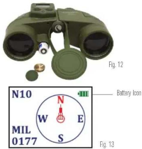
text_image
Fig. 12 N10 MIL 0177 N W E S Battery Icon Fig. 13POWER BUTTON
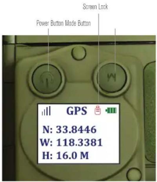
Press and hold the power button for 2-3 seconds to power the unit on and off. If the power button is pressed quickly while the unit is on, a red padlock icon will appear to the left of the battery indicator, indicating the screen lock has been activated. This freezes the screen at the moment of activating the screen lock and prevents the mode from being changed. To deactivate the screen lock, quickly press the power button again; the red padlock icon will disappear. The screen will update if applicable and pressing the mode button will now allow you to change modes.
MODE BUTTON
The mode button scrolls through the three device modes (GPS, compass, level). Press the mode button to scroll through the modes.
text_image
Screen Lock Power Button Mode Button GPS N: 33.8446 W: 118.3381 H: 16.0 MFig. 14
GPS MODE
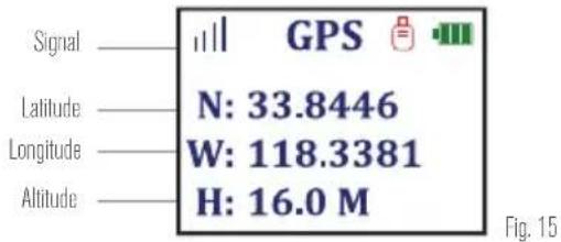
When the device is in GPS mode, a signal icon designated by four vertical bars of increasing height will appear in the upper left hand corner of the LCD screen. While a signal is being acquired, the icon will flash red. Once a signal is acquired the icon will stop flashing and turn blue. GPS mode provides latitude and longitude coordinates as well as altitude readings. Please see the disclaimer at the end of this manual regarding the accuracy of readings.
text_image
Signal GPS Latitude N: 33.8446 Longitude W: 118.3381 Altitude H: 16.0 M Fig. 15COMPASS MODE
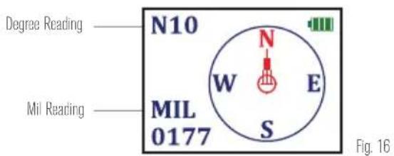
In compass mode, the screen displays a digital compass and readings (in both degrees and mils) for the bearing that the objective lenses are facing. A red stationary arrow points in the direction you are facing when looking through the binoculars while a circle containing the readings N/S/E/W rotates as the binocular is moved (the red N will always point North). The bearing that the red arrow points to is displayed in degrees and mils on the LCD screen. Keep in mind that the digital compass points to true North, which is different from the analog compass reading of the other Cavalry models.
text_image
Degree Reading N10 MIL 0177 W E S Mil Reading Fig. 16LEVEL MODE
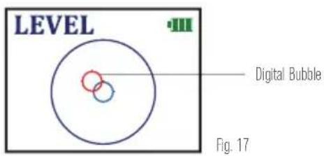
In level mode, the screen will display a large black circle with a small stationary blue circle in its center. A small red circle representing a "bubble" will move as the binoculars are tilted. When the red "bubble" aligns perfectly with the small blue circle, the binoculars are level.
text_image
LEVEL Digital Bubble Fig. 17CARE AND STORAGE
Your Celestron binocular/monocular will provide you years of dependable service if it is cared for and stored properly.
- Protect the binocular/monocular from impact and do not force any of the moving parts beyond their limits.
- Protect the optics of your binocular/monocular by putting on all lens caps when not in use.
-
Store your binocular/monocular in a cool, dry place whenever possible.
-
When storing for an extended period of time, place the binocular/monocular in a plastic bag or airtight container with a desiccant.
- Do not leave the binocular/monocular in a car on a hot/sunny day or near anything that generates heat as this may cause damage.
- Clean any dust, dirt or water that may get on the binocular/monocular or inside moving parts as soon as possible to prevent any unforeseen damage.
CLEANING
Proper cleaning of the lenses is essential to maintaining the optical integrity of your binocular/monocular. Dirty lenses diminish the amount of light transmitted through the binocular/monocular and your overall viewing experience.
- Remove any dust on the lenses with a soft lens brush or can of pressurized air.
-
Remove any fingerprints, stains or smudges from the lens surface with a soft, clean lens cloth or lens tissue by rubbing in a circular motion. Start in the middle of the lens and work your way to the edges. Breathe lightly on the lens to provide moisture if needed.
-
For a more thorough cleaning we recommend the use of a lens/optics cleaning kit available at most photo or optical shops. Follow the directions supplied with the cleaning kit for best results.
SERVICE AND REPAIR
If warranty problems arise or repairs are necessary, contact the Celestron customer service department if you live in the United States or Canada. If you live outside of these countries, please contact the dealer you
purchased your binocular/monocular from or the Celestron distributor in your country. A list of our distributors can be found on our website. www.celestron.com
WARRANTY
Your binocular/monocular is covered under the Celestron Limited Lifetime Warranty. Celestron warrants these binoculars/monoculars to be free from defects in materials and workmanship for the binoculars/monoculars usable lifetime to the original owner. Celestron will repair or replace the binoculars/monoculars which, upon inspection by Celestron, are found to be defective in materials or workmanship and within the definitions of the limits described below.
This warranty does not cover products that have been subject to abuse, misuse, physically damaged, altered, or had unauthorized repairs or modifications. This warranty does not cover defects due to normal wear and tear and other conditions.
This warranty is valid to U.S.A. and Canadian customers who have purchased their binocular/ monocular from an authorized Celestron dealer in the U.S.A. or Canada. For products purchased outside of the U.S.A. or Canada please contact your local Celestron Distributor or authorized Dealer for applicable warranty information. Additional warranty information and eligibility details can be found on the Celestron website.
This product is designed and intended for use by those 14 years of age and older. Product design and specifications are subject to change without prior notification.
FCC Note: This equipment has been tested and found to comply with the limits for a Class B digital device, pursuant to part 15 of the FCC Rules. These limits are designed to provide reasonable protection against harmful interference in a residential installation. This equipment generates, uses, and can radiate radio frequency energy and, if not installed and used in accordance with the instructions, may cause harmful interference to radio communications. However, there is no guarantee that interference will not occur in a particular installation. If this equipment does cause harmful interference to radio or television reception, which can be determined by turning the equipment off and on, the user is encouraged to try to correct the interference by one or more of the following measures:
• Reorient or relocate the receiving antenna.
- Increase the separation between the equipment and receiver.
- Connect the equipment into an outlet on a circuit different from that to which the receiver is connected.
- Consult the dealer or an experienced radio/TV technician for help.
GPS Systems and Location Accuracy Notice
The Global Positioning System (GPS) is operated by the government of the United States of America, which is solely responsible for its accuracy and maintenance. The system is subject to changes which could affect the accuracy and performance of all GPS equipment. The inherent nature of the GPS system itself limits the accuracy of the readings indicated on the Cavalry 7x50 display.
Warning
This device is intended as a supplemental navigation aide only. The user assumes all responsibility associated with the use of this product. It must not be used for any purpose requiring precise measurement of location, altitude or direction. This device should not be used for any aircraft navigation applications.
Liability Notice
In no event shall Celestron be liable for any incidental, special, indirect or consequential damages, whether resulting from the use, misuse, or inability to use this product or from the defects in the product. Some states do not allow the exclusion of incidental or consequential damages, so the above limitations may not apply to you.

For complete specifications and product information:
www.celestron.com
2835 Columbia Street • Torrance, CA 90503 U.S.A
Tel: 800.421.9649

bar
| Category | Value | |---|---| | Category 1 | 100 | | Category 2 | 100 | | Category 3 | 100 | | Category 4 | 100 | | Category 5 | 100 | | Category 6 | 100 | | Category 7 | 100 | | Category 8 | 100 | | Category 9 | 100 | | Category 10 | 100 | | Category 11 | 100 | | Category 12 | 100 | | Category 13 | 100 | | Category 14 | 100 | | Category 15 | 100 | | Category 16 | 100 | | Category 17 | 100 | | Category 18 | 100 | | Category 19 | 100 | | Category 20 | 100 | | Category 21 | 100 | | Category 22 | 100 | | Category 23 | 100 | | Category 24 | 100 | | Category 25 | 100 | | Category 26 | 100 | | Category 27 | 100 | | Category 28 | 100 | | Category 29 | 100 | | Category 30 | 100 | | Category 31 | 100 | | Category 32 | 100 | | Category 33 | 100 | | Category 34 | 100 | | Category 35 | 100 | | Category 36 | 100 | | Category 37 | 100 | | Category 38 | 100 | | Category 39 | 100 | | Category 40 | 100 | | Category 41 | 100 | | Category 42 | 100 | | Category 43 | 100 | | Category 44 | 100 | | Category 45 | 100 | | Category 46 | 100 | | Category 47 | 100 | | Category 48 | 100 | | Category 49 | 100 | | Category 50 | 100 | | Category 51 | 100 | | Category 52 | 100 | | Category 53 | 100 | | Category 54 | 100 | | Category 55 | 100 | | Category 56 | 100 | | Category 57 | 100 | | Category 58 | 100 | | Category 59 | 100 | | Category 60 | 100 | | Category 61 | 100 | | Category 62 | 100 | | Category 63 | 100 | | Category 64 | 100 | | Category 65 | 100 | | Category 66 | 100 | | Category 67 | 100 | | Category 68 | 100 | | Category 69 | 100 | | Category 70 | 100 | | Category 71 | 100 | | Category 72 | 100 | | Category 73 | 100 | | Category 74 | 100 | | Category 75 | 100 | | Category 76 | 100 | | Category 77 | 100 | | Category 78 | 100 | | Category 79 | 100 | | Category 80 | 100 | | Category 81 | 100 | | Category 82 | 100 | | Category 83 | 100 | | Category 84 | 100 | | Category 85 | 100 | | Category 86 | 100 | | Category 87 | 100 | | Category 88 | 100 | | Category 89 | 100 | | Category 90 | 100 | | Category 91 | 100 | | Category 92 | 100 | | Category 93 | 100 | | Category 94 | 100 | | Category 95 | 100 | | Category 96 | 100 | | Category 97 | 100 | | Category 98 | 100 | | Category 99 | 100 | | Total (Total) |FRANÇAIS
CAVALRY
JUMELLE
JUMELLES ET TÉLESCOPES CELESTRON CAVLARY
natural_image
Green binoculars with directional arrows indicating rotational motion (no text or symbols on the device itself)RÉGLAGE DU DIOPTRE/FOCALISATION
natural_image
Two hands adjusting a black camera module, one with a curved arrow indicating rotation (no text or symbols visible)natural_image
Illustration of a green binoculars with an arrow indicating rotation around the lens (no text or symbols)Fig. 7
ÉTANCHE/ANTIBUÉE
natural_image
Green binoculars with directional arrows indicating rotational motion (no text or symbols on the device itself)CONFIGURAR LA DIOPTRÍA / ENFOQUE
Modelos 71420, 71424, and 71426
natural_image
Green CELEKTRON 7x50 optical binoculars with visible lens and screen (no text or symbols on device body)Fig. 4
Modelo 71215
natural_image
Close-up of hands adjusting a black cylindrical device with a scroll wheel (no text or symbols visible)ADAPTABILIDAD DE TRÍPODE
natural_image
Illustration of a green binoculars with an arrow indicating rotation around the lens (no text or symbols)natural_image
Green binoculars with directional arrows indicating rotational motion (no text or symbols on the bin itself)Models 71420, 71424, and 71426
natural_image
Hand pressing a black mechanical component with an arrow indicating rotation (no text or symbols visible)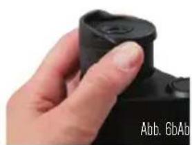
natural_image
Close-up of a hand holding a black camera lens (no visible text or symbols)natural_image
Illustration of a green binoculars with an arrow indicating rotational direction (no text or symbols)Abb. 7
natural_image
Green binoculars with directional arrows indicating rotational motion (no text or symbols on the device itself)Modelli 71420, 71424, and 71426
natural_image
Two hands adjusting a black camera module, one with a curved arrow indicating rotation (no text or symbols visible)ADATTABILITÀ DEL TREPPIEDE
natural_image
Illustration of a green binoculars with a circular arrow indicating rotational motion (no text or symbols)Fig. 7
TASTO MODE (MODALITÀ)
text_image
Valore in gradi N10 MIL 0177 Valore in mil W N E S Fig. 16MODALITÀ LIVELLO
All rights reserved. • Printed in China • 0113
This product is designed and intended for use by those 14 years of age and older.
www.celestron.com

CELESTRON
©2013 Celestron. All rights reserved.