GA201 - Garage door BERNER - Free user manual and instructions
Find the device manual for free GA201 BERNER in PDF.

| Type de produit | Motorisation pour porte de garage basculante et sectionnelle |
| Marque et modèle | Berner GA201 |
| Alimentation électrique | 230/240 V AC, 50/60 Hz |
| Consommation en veille | Approximately 5 W |
| Type de moteur | DC motor with Hall sensor |
| Vitesse de marche | Normal: approx. 135 mm/s; quick opening: approx. 220 mm/s |
| Force de traction / poussée | See rating plate |
| Éclairage intégré | Halogen lamp 12 V / 10 W (G4 socket) |
| Rail de guidage | Extremely flat (30 mm), with integrated anti-lift safety |
| Moyen d’entraînement | Synthetic or toothed belt, tension set at factory |
| Type de commande | Sequential impulse (open, stop, close, stop) |
| Fréquence radio | 868.360 MHz (4-button transmitter RC BE) |
| Protection | Protection rating: only for dry rooms |
| Dispositifs de sécurité | Obstacle detection with reversal, emergency stop (cable), photocell and pressure strip optional |
| Fonctions spéciales | Pedestrian opening, quick opening, automatic closing, slow stop, timed light, door closed indicator |
| Déverrouillage manuel | By mechanical release cable (from inside) |
| Niveau sonore | ≤ 70 dB(A) |
| Température d’utilisation | Not specified, but designed for dry indoor mounting |
| Entretien | The motor requires no maintenance. Annual check recommended by a professional |
| Garantie | 5 years on motor and control, 2 years on radio and accessories |
Frequently Asked Questions - GA201 BERNER
User questions about GA201 BERNER
0 question about this device. Answer the ones you know or ask your own.
Ask a new question about this device
Download the instructions for your Garage door in PDF format for free! Find your manual GA201 - BERNER and take your electronic device back in hand. On this page are published all the documents necessary for the use of your device. GA201 by BERNER.
USER MANUAL GA201 BERNER
natural_image
Black-and-white photo of a person cleaning a car inside a garage, no visible text or symbolsInstallation, Operating and Maintenance Instructions
Garage Door Operator
6 . 1 N o r m a l - Be t r i eb
B Required Tools for Installation
2
1 Important Not
1.1 Important safety instructions
1.1.1 We shall be exempt from our warranty obligations and product liability in the event that 7
1.2 Important instructions for safe installation 7
1.2.1 Prior to installation 7
1.2.2 In carrying out the installation work 7
1.3 Warnings
1.4 Maintenance advice
1.5 Information on the illustrated section

Illustrated section
2 Installation Instructions
2.2 Required clearance for installing the operator 39
2.3 Door latch on a sectional door 39
2.4 Centrally positioned lock on a sectional door 39
2.5 Off-centred reinforcement profile on a sectional door 39
2.6 Door latches on an up-and-over door 39
2.7 Up-and-over doors with a forged iron door handle 39
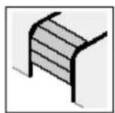
2.8 Guiding rail
2.9 Prior to installation: guiding rail 39
2.10 Installation: guiding rail
2.11 Operation types: guiding rail
2.11.1 Manual operation
2.11.2 Automatic operation 39
2.12 Establishing the "CLOSE" end-of-travel position
by installing the limit stop
2.13 Tensioning the drive medium
3 Putting into service
3.1 Notes on work involving electrics/electronics 40
3.2 Putting the operator into service 40
3.2.1 Deleting the door data 40
3.2.2 Programming the operator (learning procedure) 40
3.2.3 Setting forces and conduct after a safety shutdown 41
3.2.4 Setting the door speed
4 Installation: garage door operator and accessories
4.1 Notes on work involving electrics/electronics 41
4.2 Installing the radio receiver 41
4.3 Connecting an external radio receiver 41
4.4 Electrical connection / Connection clips 41
4.5 Connecting Additional Components / Accessories 42
4.6 Connecting external "impulse" buttons to start or stop the travel of the door 42
4.7 Connecting internal "impulse" button IT3b 42
4.7.1 "Impulse" button: start or stop the travel of the door 42
4.7.2 Light button: switch on / off operator lightning 42
4.7.3 Button: switch on / off radio system 42
4.8 Connecting a cutout switch or a wicket door contact 42
4.9 Connecting a photocell
4.10 Connecting A2-wire light barrier 42
4.11 Connecting an electronic switch barth of the 2 borders 8,2k 42
4.12 Connecting an optosensoric switch barth of the b o r de r s
4e13 s Connecting a warning lamp 7 42
4.14 7 Connecting an external lamp 42
4.15 Connecting a "door closed" display to the optional relay 42
5 Special functions and any other adjustment possibilities of the garage door operator 43
5.1 Second opening position (airing position) 43
5.1.1 Programming the second opening position (airing position) 43
5.2 Defined direction instructions 43
5.3 Quick-opening function 43
5.4 Soft-stop 43
5.5 Short return to the position "door closed" 43
5.6 Automatic door locking 43
5.6.1 Programmable opening time/advance warning time 43
5.6.2 Automatic door locking "closed" 44
39 "Door closed": programmable lightning time 44 39
6 Operation of the garage door operator 44
6.1 Normal operation 44
6.2 Operation following actuation of the mechanical / manual release 44
6.3 Operator lighting error message / LED-diagnosis 44
6.4 Measures following error message 45
39.5 Malfunctions and remedy 45
6.5.1 Operator fails to start up 45
6.5.29 Operator fails to work with hand transmitter 45
6.5.3 Operator fails to work with externally connected
39 c o n t r o l s / b u t t o n s
6.5.4 Door fails to close or open fully 46
6.5.5 Operator responds but door fails to open 46
6.5.639 The closing door changes direction 46
6.5.7 ^40 Lights damaged 46
6.5.8 Radio system: range too low 4 6 40
7 Terms and Conditions of the Warranty 46
8 Technical Data 46
9 _41 Dismantling and Disposal 47
10 Circuit Board Overview 48
Copyright.
No part of this instruction manual may be reproduced without our permission.
Subject to changes.
Dear Customer,
Thank you for choosing this quality product from our company. Please keep these instructions safe for later reference!
Please observe the following instructions, they provide you with important information on the safe installation and use of your Garage Door Operator, thus ensuring that this product will give you satisfaction for many years to come.
Please observe all our safety and warning advices which are especially marked with ATTENTION and Note.

ATTENTION
Installation, maintenance and repair have to be completed by a technical expert.
Note
To assure safe use and maintenance, inspect and test log book and instructions must be available for the final customer.
1 IMPORTANT NOTES

ATTENTION
Incorrect installation or handling of the operator could result in serious injury. Please therefore follow these instructions fully and with extreme care!
1.1 Important safety instructions
The garage door operator is intended exclusively for the automatic opening and closing of spring-balanced up-and-over doors and sectional doors for the private /
non-commercial use as well as for garage doors with higher load (e.g. underground car parks and collective car parks).
Please respect the manufacturer instruction concerning the combination door – operator. Possible danger in terms of the norms EN 12604 and EN 12453 will be avoided by the construction and mounting according to our specifications. Doors which are suited in public area and dispose of only one protective device, e.g. force catch, are only to be operated under supervision.
1.1.1 Warranty
We shall be exempt from our warranty obligations and product liability in the event that the customer carries out his own structural changes or undertakes improper installation work or arranges for same to be carried out without our prior approval and contrary to the installation guidelines we have provided.
Moreover, we shall accept no responsibility for the inadvertent or negligent operation of the operator and accessories nor for the improper maintenance of the door and/or its counterbalance mechanism.
Batteries and light bulbs are also not covered by the warranty.
Note
In case of failure of the garage door operator, a technical expert has to be mandated immediately with the inspection / repair.
The design of the operator is not suitable nor intended for the opening and closing of heavy doors, i.e. doors that can no longer be opened or closed manually.
Before installing the operator, it is therefore necessary to check the door and make sure that it can also be easily moved by hand.
To do this, raise the door approx. 1 metre and then let it go. The door should retain this position, moving neither up nor down. If the door should move in any of the two directions, there is a risk that the compensating springs are defective or incorrectly adjusted. In this case increased wear and malfunctioning of the door system can be expected.

CAUTION: Danger to life!
Do not attempt to change, readjust, repair or move the compensating springs for the door's counterbalance mechanism or their holders. The springs are under great tension and can cause serious injury.
In addition, check the entire door system (pivots, door bearings, cables, springs and fastenings) for wear and possible damage. Check for signs of rust, corrosion or fractures. The door system may not be used if repair or adjustment work needs to be carried out. Always remember that a fault in the door system or a misaligned door can also cause injury.
Note
Before installing the operator and in the interests of personal safety, make sure that any work needed on the door's compensating springs is carried out by a special engineer. This also applies to any necessary maintenance or repair work. Only both correct mounting and maintenance through a competent/expert person in accordance with the instructions can assure a safe and intended functionality of mounting.
1.2 Important instructions for safe installation
Any further processing must ensure that the national regulations governing the operational safety and the operation of electrical equipment are complied with. Hereby the national directives have to be respected. Possible danger in terms of the norms EN 12604 and EN 12453 will be avoided by the construction and mounting according to our specifications.
1.2.1 Before installing the garage door operator, check that the door is in a good mechanical condition and is correctly balanced. Further check whether the door opens and closes in the proper manner (see section 1.1.2).
In addition, any of the door's mechanical locks and latches not needed for power operation of the garage door should be immobilised. This includes in particular any locking mechanisms connected with the door lock (see sections 2.2 to 2.3).
The garage door operator is designed for use in dry buildings and therefore may not be installed outdoors. The garage ceiling must be constructed in such a way as to guarantee safe, secure anchoring of the operator. In the case of ceilings that are too high or too lightweight, the operator must be attached to additional braces.
1.2.2 In carrying out the installation work
Note
The use of the delivered mounting materials regarding their suitability for the intended mounting place must be checked by the installation person. / The person who installs the operator must check the use of the delivered mounting materials regarding their suitability for the intended mounting place.
The clearance between the highest point of the door and the ceiling (also when the door is opening) must be at least 30 mm (see fig. 1.1a / 1.1b). If there is inadequate clearance, the operator may also be installed behind the opened door, provided sufficient space is available. In such instances an extended door link arm must be used. The garage door operator can be positioned off-centre by max. 50 cm, the exception being sectional doors with high-lift tracks (track application "H"), where a special track fitting is required.
The required shockproof electric socket allowing the operator to be connected to the electricity supply should be installed at a distance of approx. 50 cm from the operator head.
Please check these dimensions!
1.3 Warnings
Permanently installed controls (such as buttons or similar devices) should be installed within sight of the door but well away from any moving parts and at a height of at least 1.5 metres. It is vital that they are installed out of the reach of children!
Note
A caution notice warning about the trap risk must be permanently fixed in a conspicuous place close to the permanently installed buttons used to actuate the operator.
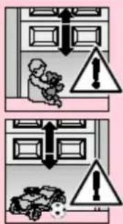
text_image
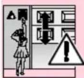
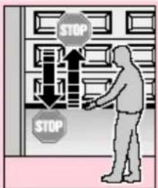
Safety warning illustration showing incorrect safety rules for a person in a room with warning symbols and hazard signs.Make sure that
- neither persons nor objects are located within the door's range of travel.
- children do not play around with the door system!
- the cord of the mechanical release on the carriage cannot get caught up in the ceiling's support system or in any other protruding parts of vehicles or the door.

ATTENTION
For garages without a second entrance, an emergency release must be fitted to ensure that is no danger of getting locked in. This must be ordered separately and its function checked once a month.

ATTENTION
Do not allow anyone to hang bodily from the pull cord with knob!
1.4 Maintenance advice
The garage door operator is maintenance-free. For your own safety, however, we recommend that you have the door system checked according to manufacturer information by service engineers qualified to inspect and service garage doors.
Inspection and maintenance should only be effected by a competent person, please contact your supplier for this. A visual inspection can be effected by the operator.
Regarding necessary repairs contact your supplier. We shall accept no responsibility for improper and unprofessional repairs.
1.5 Information on the illustrated section
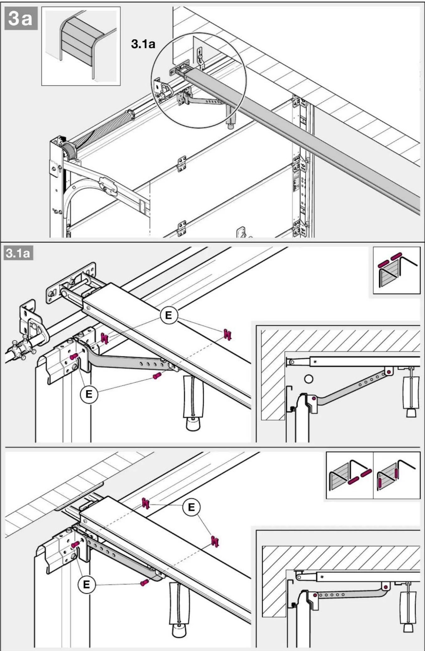
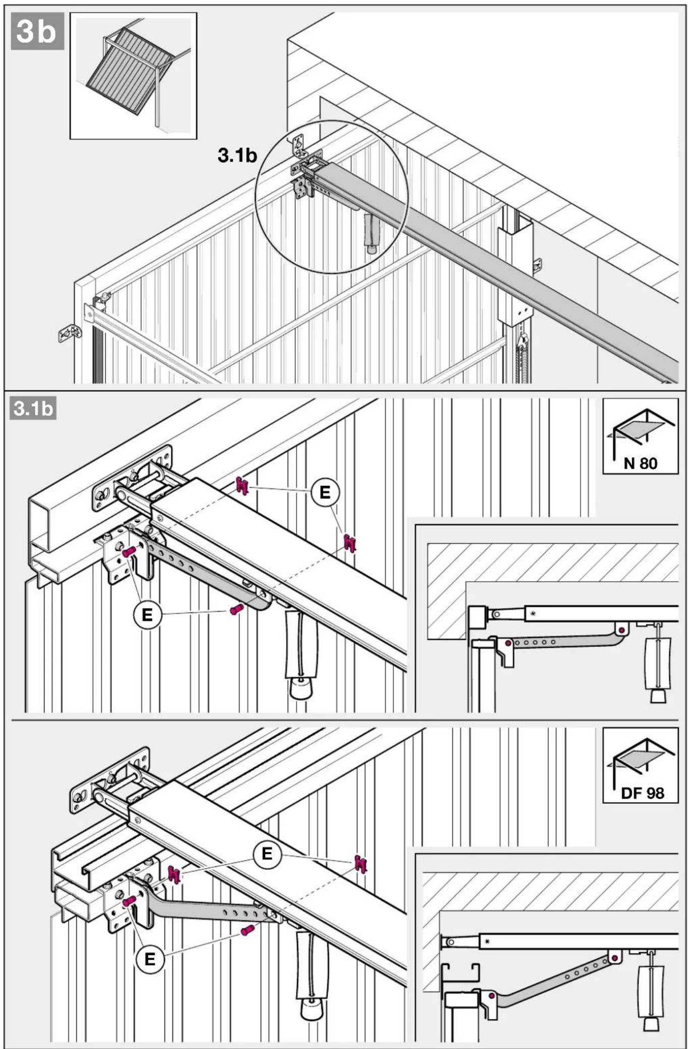
The illustrated section shows installation of the operator on an up-and-over door. Where installation differs for a sectional door, this is shown in addition.
In this instance, letters are assigned to the figures as follows:
a
is assigned to the sectional door and
b
to the up-and-over door.
Some of the figures also include the symbol shown below together with a text reference. This refers to specific text in the ensuing text section to provide you with important information regarding installation and operation of the garage door operator.
Example:
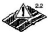
= see text section, point 2.2
Furthermore, the following symbol, which marks factory settings, is illustrated in the picture section and text section which explain the menu of the operator.

= factory settings
Copyright.
No part of this instruction manual may be reproduced without our permission.
Subject to changes.
TABLE DES MATIERES PAGE
A Articles livrés
text_image
Safety warning sign with pink triangular warning triangle and X-shaped cross symbol, indicating hazard or failure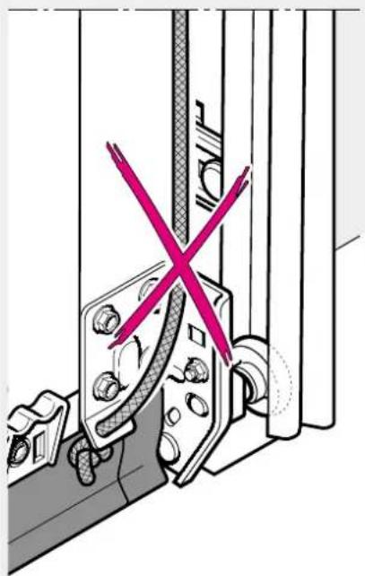
natural_image
Technical diagram showing a mechanical assembly with a red X mark indicating a crossed-out section (no text or symbols present)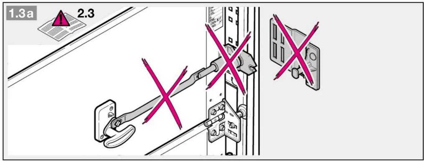
text_image
1.3a 2.3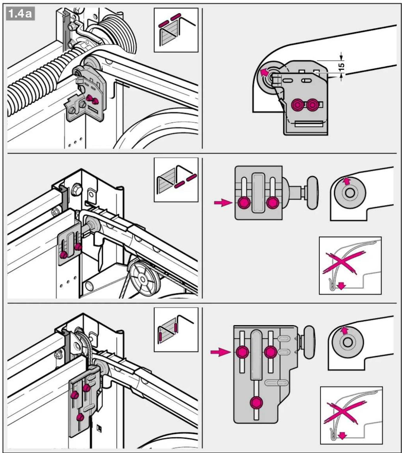
text_image
1.4a 15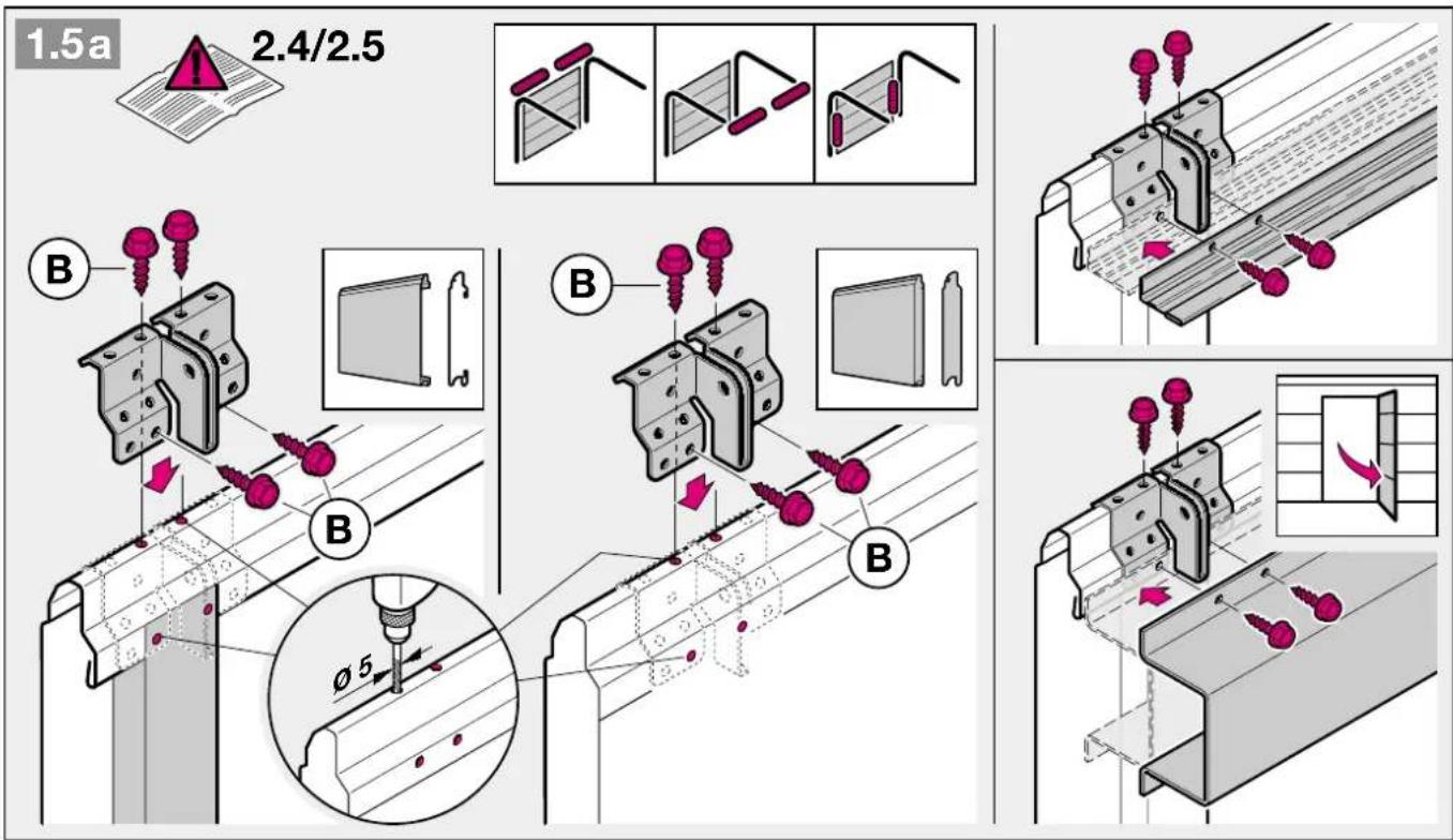
text_image
1.5a 2.4/2.5 B B B φ5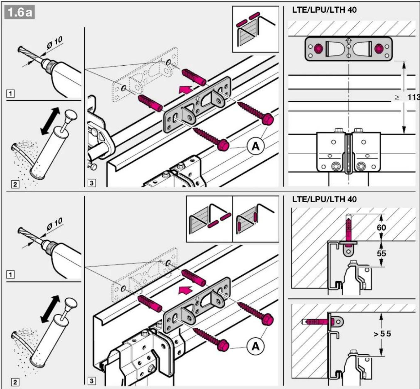
text_image
1.6a LTE/LPU/LTH 40 1 2 3 ≥ 113 LTE/LPU/LTH 40 1 2 3 60 55 > 55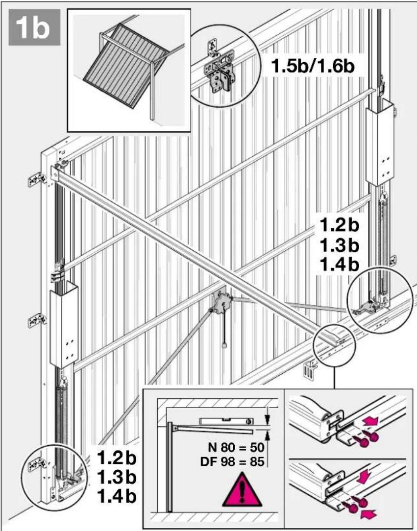
text_image
1b 1.5b/1.6b 1.2b 1.3b 1.4b 1.2b 1.3b 1.4b N 80 = 50 DF 98 = 85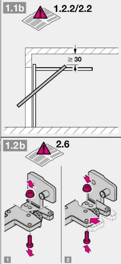
text_image
1.1b 1.2.2/2.2 ≥ 30 1.2b 2.6 1 2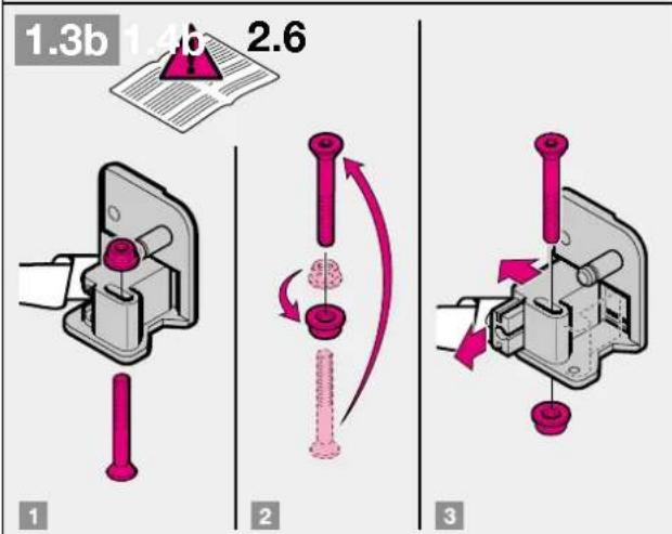
text_image
1.3b 1.4b 2.6 1 2 3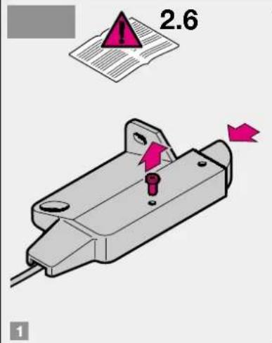
text_image
2.6 1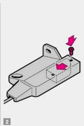
natural_image
3D mechanical component diagram showing a housing with mounting holes and a highlighted section (no text or symbols)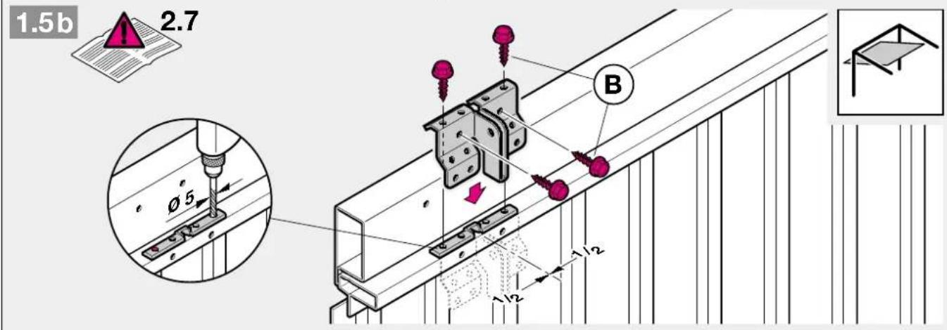
text_image
1.5b 2.7 Ø5 B 1/12 1/12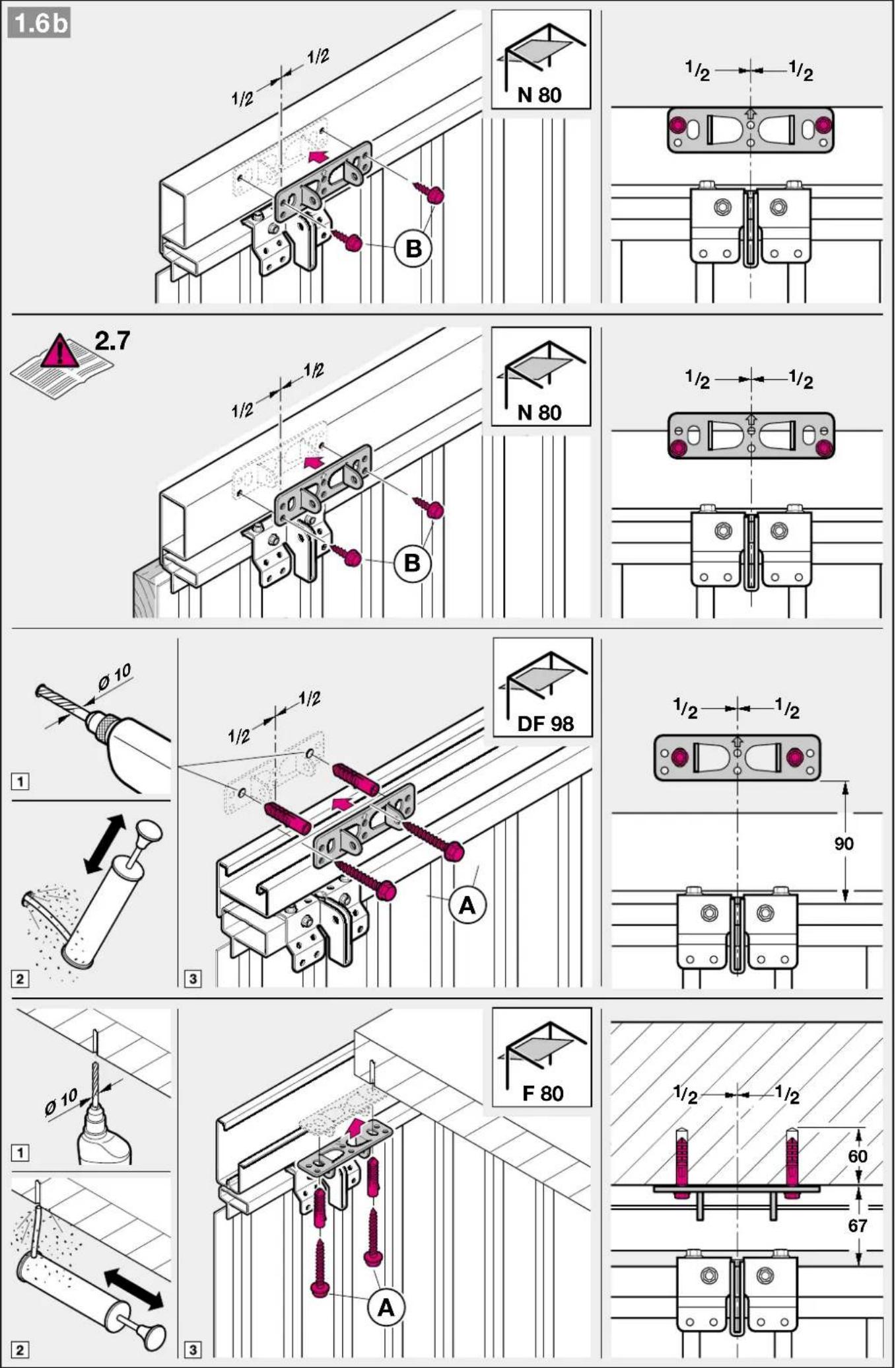
text_image
4.1 2.11.1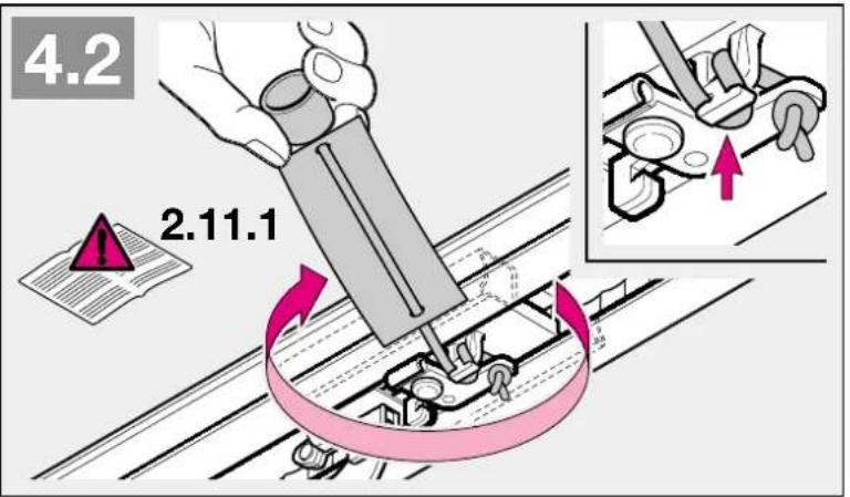
text_image
4.2 2.11.1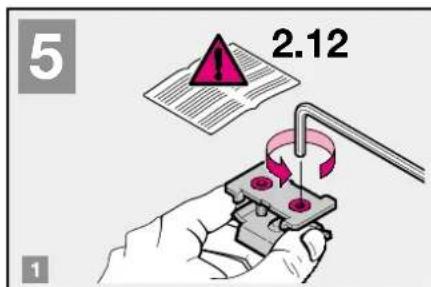
text_image
5 2.12 1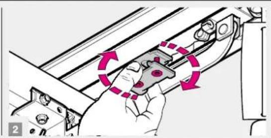
natural_image
Illustration of a hand holding a mechanical component with motion arrows indicating rotation (no text or symbols)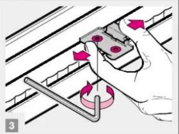
natural_image
Illustration of a hand using a tool to adjust a mechanical component (no text or symbols visible)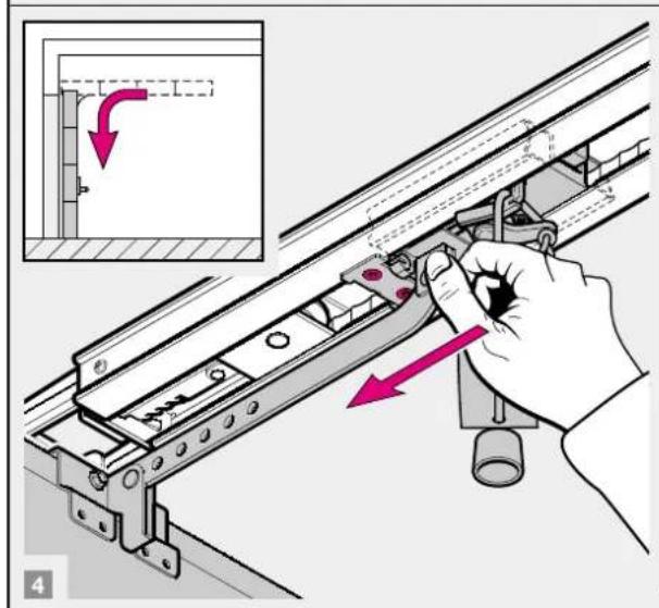
text_image
Technical diagram showing a hand operating a rail-mounted device with a highlighted section and directional arrows indicating movement or assembly.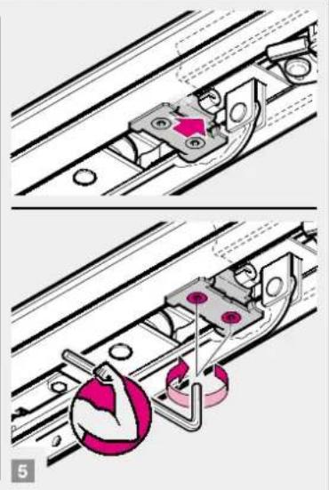
natural_image
Mechanical assembly diagram showing two steps of a sliding mechanism with no visible text or symbols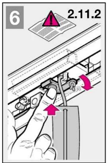
text_image
6 2.11.2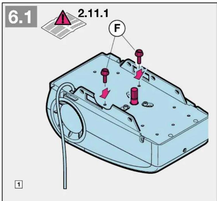
text_image
6.1 2.11.1 F 1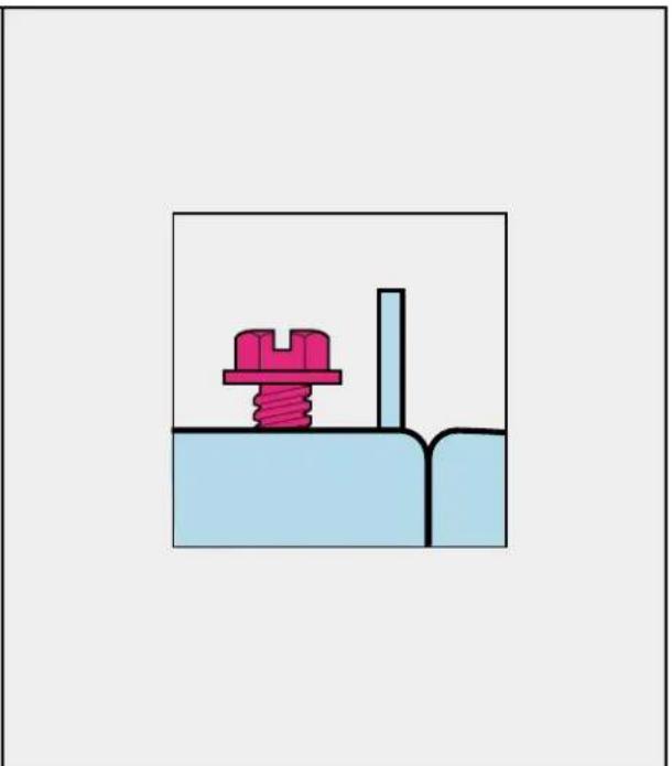
natural_image
Simple diagram of a mechanical assembly with a spring and block, no text or symbols present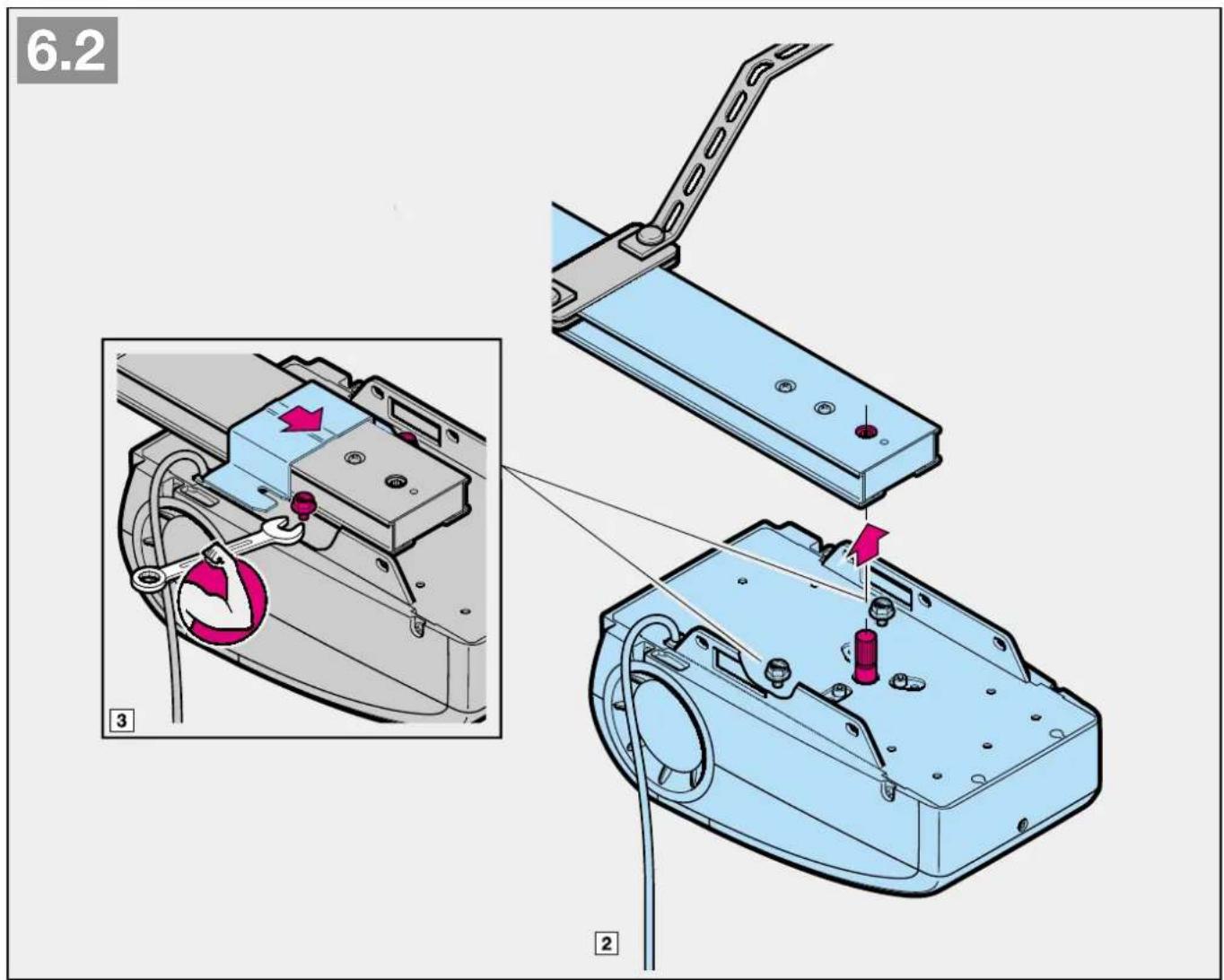
text_image
6.2 3 2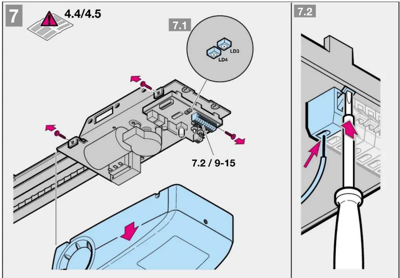
text_image
7 4.4/4.5 7.1 LD3 LD4 7.2 / 9-15 7.2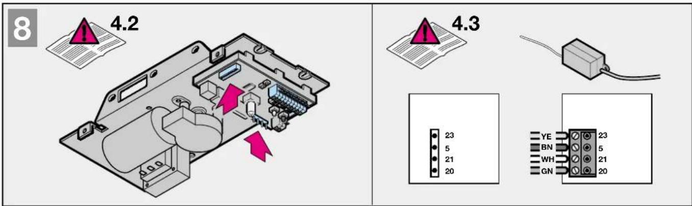
text_image
8 4.2 4.3 23 5 21 20 YE BN WH GN 23 5 21 20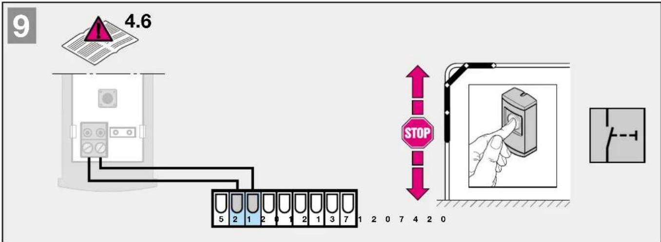
text_image
9 4.6 STOP 5 2 1 2 0 1 2 1 3 7 1 2 0 7 4 2 0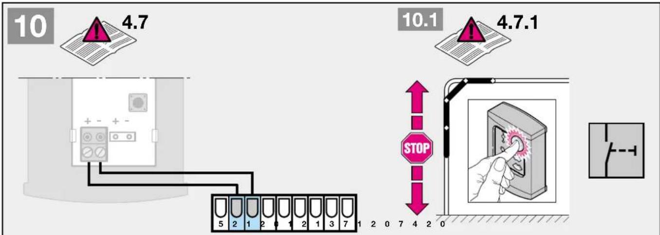
text_image
10 4.7 10.1 4.7.1 STOP 5 2 1 2 0 1 2 1 3 7 1 2 0 7 4 2 0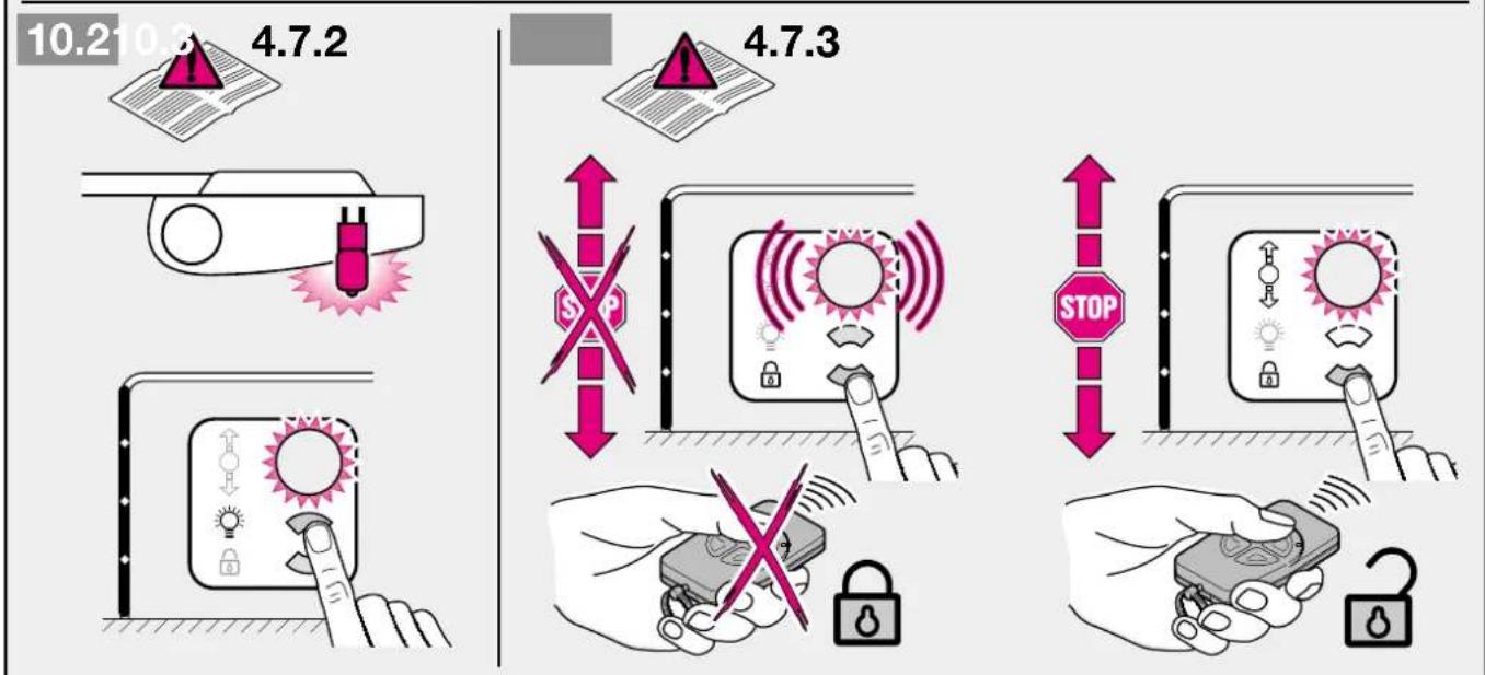
text_image
10.2 10.3 4.7.2 4.7.3 STOP STOP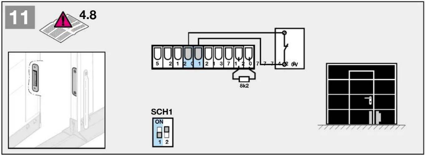
text_image
11 4.8 5 2 1 2 0 1 2 1 3 7 1 2 0 7 7 7 4 2 0V 8k2 SCH1 ON 1 2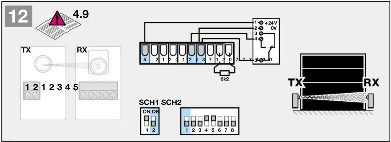
text_image
12 4.9 TX RX 1 2 1 2 3 4 5 SCH1 SCH2 ON ON 1 2 1 2 3 4 5 6 7 8 8k2 1 +24V 2 0V 3 4 5-02-0 TX RX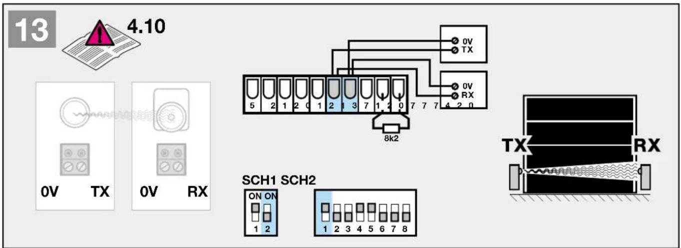
text_image
13 4.10 0V TX 0V RX 8k2 SCH1 SCH2 ON ON 1 2 1 2 3 4 5 6 7 8 TX RX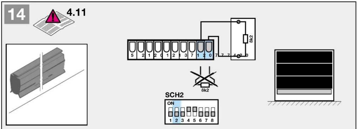
text_image
14 4.11 5 2 1 2 0 1 2 1 3 7 1 2 0 7 7 7 4 2 0 8k2 SCH2 ON 1 2 3 4 5 6 7 8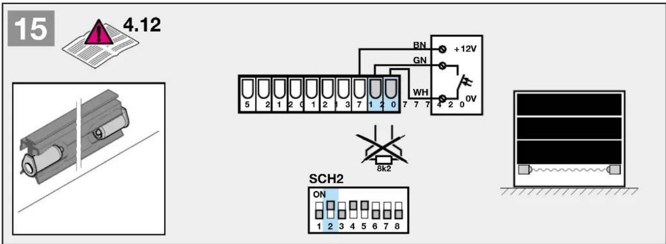
text_image
15 4.12 BN +12V GN WH 0V 5 2 1 2 0 1 2 1 3 7 1 2 0 7 7 7 4 2 0 8k2 SCH2 ON 1 2 3 4 5 6 7 8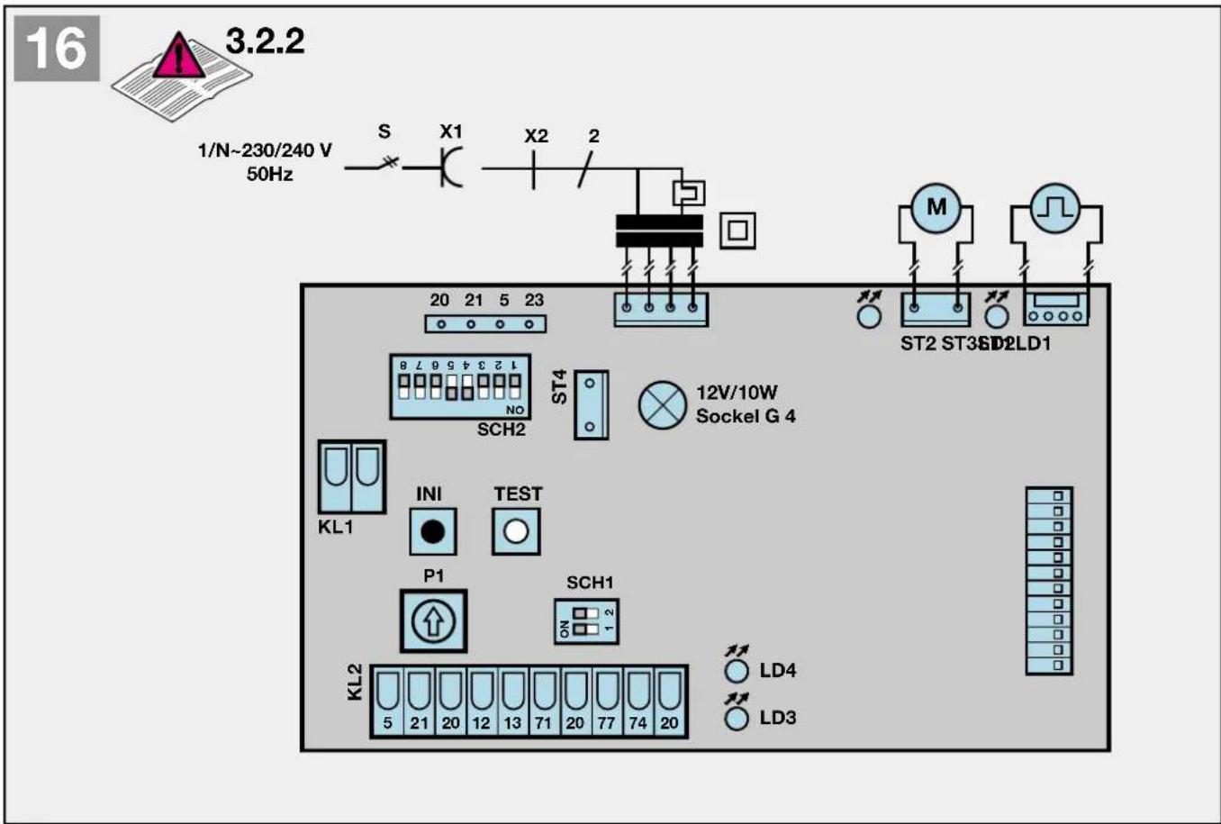
text_image
16 3.2.2 1/N~230/240 V 50Hz S X1 X2 2 20 21 5 23 ST2 ST3SD2LD1 M SCH2 ST4 12V/10W Sockel G 4 KL1 INI TEST P1 SCH1 KL2 LD4 LD3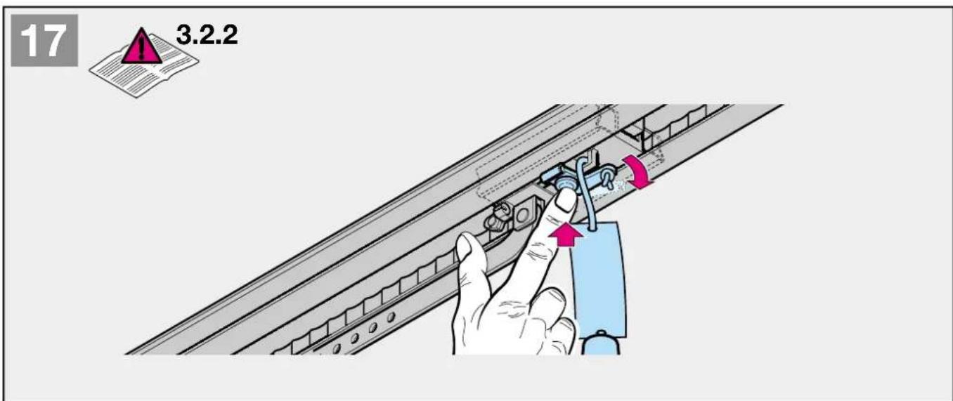
text_image
17 3.2.2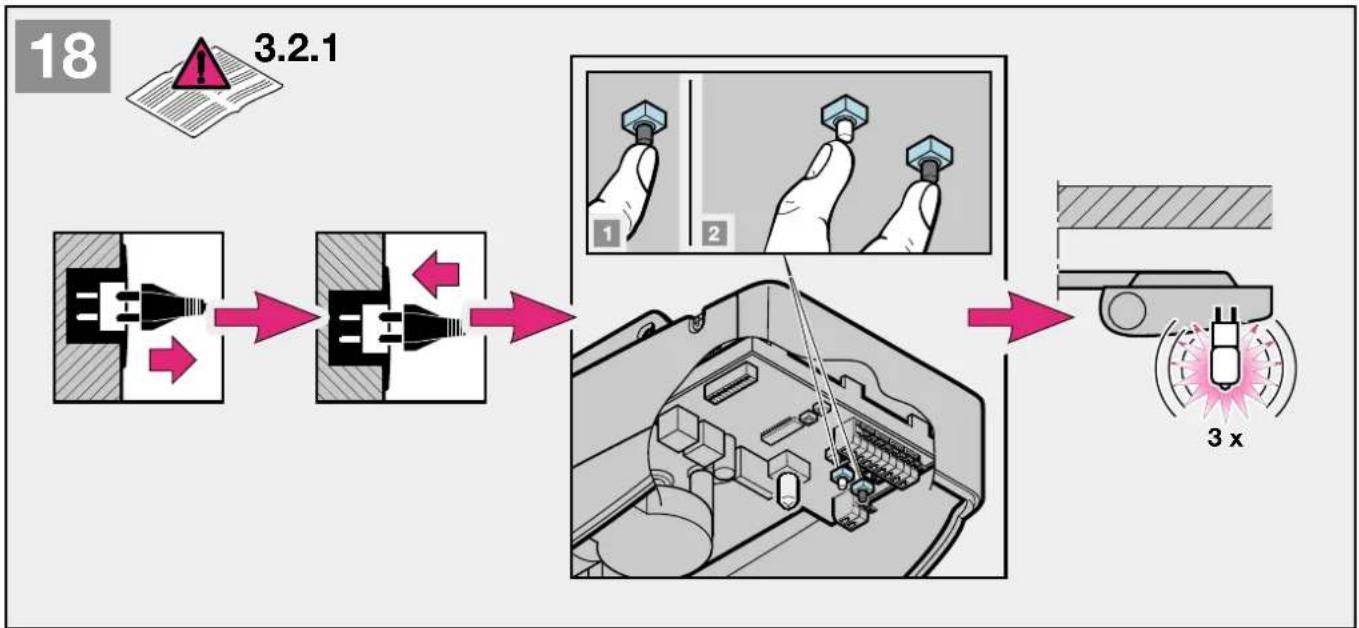
flowchart
graph LR
    A["3.2.1"] --> B["Switch"]
    B --> C["Internal Control Valve"]
    C --> D["Internal Control Valve with Pin 1"]
    C --> E["Internal Control Valve with Pin 2"]
    D --> F["Internal Control Valve with Pin 3"]
    E --> G["Internal Control Valve with Pin 4"]
    F --> H["Displacement Gauge"]
    G --> I["Displacement Gauge with 3x x displacement"]
flowchart
graph TD
    A["1: Plug-in plug"] --> B["2: Valve 6 sec."]
    B --> C["3: Hand tool 2 x"]
    C --> D["4: Hand tool 1 sec."]
    D --> E["5: Assembly 3 x"]
    E --> F["6: Transport 2 x"]
text_image
20 3.2.4 P121

4.13
text_image
max. 230/240 V AC / 300 W PE N L SCH2 ON 1 2 3 4 5 6 7 8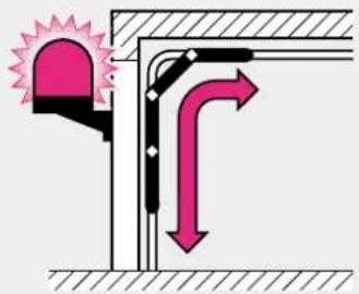
text_image
Diagram showing airflow or ventilation system with a bell icon and directional arrows indicating flow direction22

4.14
text_image
max. 230/240 V AC / 300 W PE N L SCH2 ON 1 2 3 4 5 6 7 8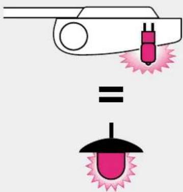
text_image
Diagram illustrating a laser welding process with pink laser and black tip, showing equal displacement23

4.15
text_image
max. 230/240 V AC / 300 W PE N L SCH2 ON 1 2 3 4 5 6 7 8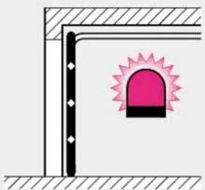
natural_image
Simple line drawing of a corner junction with a pink warning symbol (no text or labels)2 MONTAGEANLEITUNG
Hinweis
text_image
STOP STOP2 Installation Instructions
Note
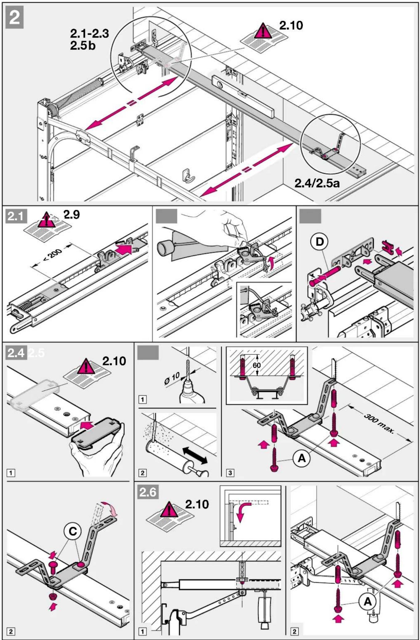
Always cover the operator before drilling, since dust and chippings can lead to malfunctions.
2.2 Required clearance for installing the operator
When installing the operator, the clearance between the highest point of the door on opening and the ceiling must be at least 30 mm (see fig. 1.1a / 1.1b). Please check these dimensions!
2.3 On a sectional door the internal mechanical latch must be completely dismantled (see figure ).

ATTENTION
When installing the operator, the pull cord must be removed. (see figure 1.2a)
2.4 Centrally positioned lock on a sectional door
For sectional doors with a centrally positioned lock, affix the lintel bracket attachment and the door link bracket off-centre (see fig.).
2.5 Off-centred reinforcement profile on a sectional door
In the case of an off-centred reinforcement profile on a sectional door, fix the door link bracket to the nearest reinforcement profile on the left or right (see fig. 1.5a).
Note
Wooden doors
Divergent from the illustrated section, these doors require wood screws 5 x 35 from the accessory bag of the door (drilling ∅ 3 mm).
2.6 The mechanical door latches on an up-and-over door must be immobilized (see figure 1.2b/1.3b/1.4b). In the case of door models not listed here, the catches must be locked on site.
2.7 Note
Up-and-over doors with a forged iron door handle
Divergent from the illustrated section (see fig. 1.5b / 1.6b), these doors require the lintel bracket attachment and the door link bracket to be affixed off-centre.
2.8 Guiding rail

ATTENTION
Dependent from the respective application object, the garage door operators have to be utilised exclusively using the guiding rails recommended by (see product information).
2.9 Before installing the guiding rail
Note
Before the guiding rail is mounted g, the boom has to be pushed approx. 20 cm from the end-of-travel position CLOSE to the end-of-travel position OPEN in the clutched in position. This is no more possible in the clutched in position as soon as the limit stop and the operator are mounted (see figure 2.1).
2.10 Mounting the guiding rail
Note
For operators in underground car parks and collective car parks it is necessary to fix the guiding rail with a second hitch under the garage ceiling; it is mounted according to figure 2.4 and 2.6.
2.11 Operation types: guiding rail
The guiding rail has two different operation types:
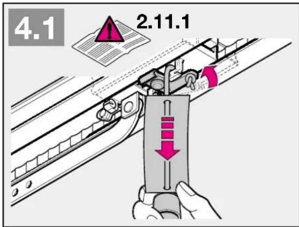
2.11.1 Manual operation (see figure 4.1)
The guiding hitch is declutched from the flange lock / belt lock; i.e. there is no direct connection between the door and the operator, so that the door can be handled manually.
To declutch the guiding rail, the wire of the mechanic unlocking must be pulled.
Note
If the guiding slide is in the position CLOSED when declutching, the wire of the mechanic unlocking must be pulled until the guiding slide with the rail has been moved as far as it can no more hook into the limit stop (approx. 3 cm sliding way). To operate the door permanently manually, the wire has to be fixed to the guiding slide as shows figure 4.2.

ATTENTION
In countries where the norm EN 13241-1 are valid, the garage door operator upgraded by a competent person on a sectional door without spring breakage saving, the responsible installer has to mount also a upgrade set at the guiding slide. This set consists of both a screw which protects the guiding slide from an uncontrolled release and a new pull unit, on which the figures show how to handle the set and the guiding slide for the two operation types of the guiding slide.
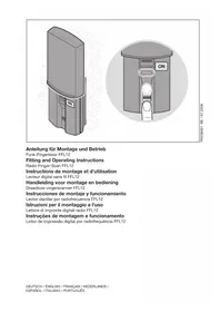
2.11.2 Automatic operation (see figure 6)
The flange lock / belt lock is clutched in the guiding slide, i.e. the door and the operator are connected with each other, so that the door and the operator can be handled together.
To prepare the guiding slide to the clutching, the green button must be pushed. Afterwards the flange / belt have to be moved to the direction of the guiding slide until the flange lock / belt lock clutches into it.

CAUTION
Do not insert fingers into the boom while the door is moving ▶ trap risk!
2.12 Establishing the "CLOSE" end-of-travel position by installing the limit stop (see figure 5)
1) The limit stop for the end-of-travel position "CLOSE" has to be put loosely in the guiding rail between guiding slide and door and the door has to be handled manually to the end-of-travel position "CLOSED". Thus the limit stop is pushed close to the right position. After reaching the end-of-travel position "CLOSED", the limit stop has to be pushed close to the guiding slide and fastened afterwards.
Note
If you are unable to push the door manually into the desired OPEN or CLOSE end-of-travel positions, this indicates that the door mechanics are too sluggish to be used with the garage door operator and must therefore be checked (see section 1.1.2)!
2.13 Tensioning the drive medium
The synthetic belt / toothed belt of the operator boom has been pretensioned at the factory for optimum performance. During the starting and braking phases of larger doors it can happen that the belt hangs out of the boom profile temporarily. However, this does not pose a technical disadvantage nor does it have any negative effect on the operator's function and service life.
3 Putting into service
3.1 Notes on work involving electrics/electronics

ATTENTION
The following points apply to all work involving electrics/electronics:
- Electrical connections may only be made by a qualified electrician!
- On-site electrical installation must comply with the relevant safety regulations (230/240 V AC, 50/60 Hz)!
- Before working on the operator, always unplug from the mains!
- External voltage at any of the controls connecting terminals will completely destroy the electronics!
- To avoid malfunctions, ensure that the control cables of the operator (24 V DC) are laid in an installation system separate to other supply lines (230 V AC)!
3.2 Putting the operator into service
The operator features a memory (fail-safe even in the event of a power failure) where the door-specific data (distance of travel, forces necessary for moving the door etc.) acquired during the learning procedure are stored and updated during subsequent travel cycles. This data is only applicable to this particular door. If another door is to be used or if the running behaviour of the door has greatly changed (e.g. on subsequent adjustment of the limit stop or fitting of new springs etc.), the data must be deleted and the operator reprogrammed.

ATTENTION
Initial operation must be carried out by a specialist. Putting into service must be recorded in writing. The operator is just one
constituent part of the overall door system.
The company responsible for the overall door system issues the Declaration of Conformity and attaches the CE Mark of Conformity. Attaching the CE Mark of Conformity to the door and issuing the EC Declaration of Conformity documents conformity with the EC Machines Directive.
3.2.1 Deleting the door data (see figure 18)
If despite several attempts, you are not successful in completing the learning procedure, we recommend that the read-in data be reset. The read-in data can be deleted as follows:
1) Unplug from the mains.
2) Plug back into the mains.
3) Press the black button and then in addition the white button and keep these pressed until the lamp starts flashing 3x.
4) Release the buttons.
5) All the data has now been deleted.
In the ex factory state, the door data is deleted and the operator can be immediately programmed ▶ see section 3.2.2 - Programming the operator
Note
Further signals from the operator lighting (flashes repeatedly on inserting the mains plug) are explained in section 6.3.
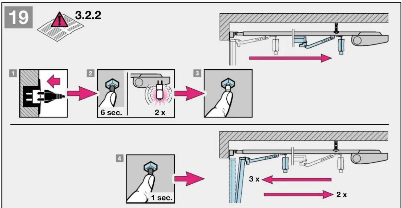
3.2.2 Programming the operator (see figure 19)

ATTENTION
Since during the learning/programming procedure the force cutoff is without function, it is essential that the installer stays with
the equipment and exercises increased vigilance.
Please also bear in mind that the learning procedure automatically ends at the "CLOSE" position.
1) Plug into the mains. When the operator is plugged into the mains for the very first time, the operator lighting flashes one or three times. Check once again whether the carriage on the door link has engaged (see fig. 7): DIP switches 1 and 2 (SCH1) and 4 and 5 (SCH2) are at "ON". DIP switches 1 - 3 and 6 - 8 (SCH2) are at "OFF".
2) Press the black button (for approx. 6 sec.) until the lamp starts flashing. Allow to flash twice, then release the "learn" button.
3) Now press the white operating button so that the door can travel to its "OPEN" position. The door moves as long as the white button stays pressed (permanent contact). Once the button is released, the door stops immediately. The next time the button is pressed, the door travels in the opposite direction. This procedure is repeated until the desired "OPEN" position is reached. When in its "OPEN" position, the door must not be allowed to press against its mechanical limit stop (rubber stopper). This could otherwise give rise to an error message (4 flashing signals and abrupt termination of the learning procedure). In its "OPEN" position the door must maintain a minimum distance of approx. 5 cm to its limit stop.
4) Briefly press the black "learn" button. Your operator carries out the remaining settings automatically! The door travels slowly to the "CLOSE" position. During this cycle, the distance of travel is learned (lamp flashes twice). The door then opens again twice and closes again twice in order to learn the necessary current alues (lamp flashes three times).
5) On completing the 5 learning cycles, the door is at the "CLOSE" position, the operator lighting switches off.
The operator is now programmed ready for operation.
Note
If the force is insufficient for the learning cycle, it can be increased as follows:
By pressing the black button for at least 3 sec. during learning cycle, the max. admissible shut down speed will be switched from 50% to 40%.
The successful switching is indicated by the luminosity (approx.
1 sec.) of the halogen lamp. Repeat this procedure for a new learning cycle.
If the force or speed is insufficient for the learning cycle, the force/speed can be increased from 30 % to 50 % via the DIL 4. Start the learning procedure once again.
For sectional doors, we recommend setting the DIL 4 to "OFF" before starting the learning phase.
3.2.3 Setting the maximum forces
The required forces for opening and closing the door, which were learned and stored during the learning phase, are updated also during the subsequent travel cycles.
That's why, if the running action of the door gets increasingly sluggish (e.g. spring tension slackens), it is important for safety reasons that these values do not infinitely reset themselves, as any necessary manual operation of the door could otherwise present a possible safety risk (e.g. door could crash to the floor).
The actually required forces are firmly memorised on the microprocessor during memorisation – safe from errors and power failure. The power tolerance at delivery is suitable for the operation of standard doors. If the memorised power is exceeded during closure, an obstacle release of 300 mm in “OPEN” direction will be effected. If the power values are exceeded during opening, a short reverse will be effected, i.e. the operator moves a short way to the closure direction.
Note
The obstacle release in “CLOSE” direction can be switched from 300 mm reverse to complete opening. Switching is effected if the black button is pressed for at least 3 sec. during the first force learning cycle in opening direction (first cycle after memorisation). The successful switching is indicated by the luminosity of the halogen lamp. If the function “automatic closing” is selected, the door generally opens completely after having met an obstacle. For a new learning process this procedure has to be repeated.
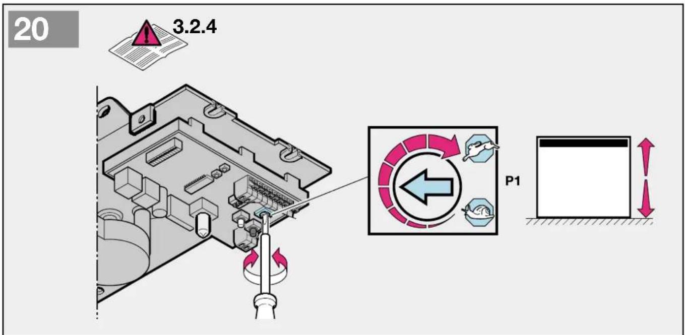
3.2.4 Setting the door speed
The door speed of the operator can be changed if necessary. To set the speed a potentiometer is available, which is accessible after opening the vision panel and is marked with P1 (see figure 20.2).
Herewith the speed is augmented through turning clockwise and reduced anticlockwise. The speed is factory set on max. (P1 on right stop).
Note
After changing the door speed the operator has to be newly programmed!
4 Installation: garage door operator and accessories
4.1 Notes on work involving electrics/electronics

ATTENTION! The following points apply to all work involving electrics/electronics:
- Electrical connections may only be made by a qualified electrician!
- On-site electrical installation must comply with the relevant safety regulations (230/240 V AC, 50/60 Hz)!
- Before working on the operator, always unplug from the mains!
- External voltage at any of the controls connecting terminals will completely destroy the electronics!
- To avoid malfunctions, ensure that the control cables of the operator (24 V DC) are laid in an installation system separate to other supply lines (230 V AC)!
4.2 Connecting the radio receiver
The radio receiver is plugged in as follows:
Plug connection (see figure 8). The receiver is plugged into the corresponding connector plug-in on the operator head. Check that the plug has properly engaged. With regard to programming hand transmitter buttons into the receiver, please refer to the corresponding instructions.
4.3 Connecting an external radio receiver \*
The radio receiver is plugged in as follows:
The plug of the receiver is plugged into the corresponding 4-pole corrector jack (see figure ).
- the green ledge (GN) to the clamp 20 (0 V)
- the white ledge (WH) to the clamp 21 (channel 1)
- the yellow ledge (YE) to the clamp 23 (channel 2)
- the brown ledge (BN) to the clamp 5 (+24 V)
Note
The antenna flex of the radio receiver should not touch metal objects (nails etc.). The best sending position has to be found by trying. GSM 900- mobile phones can influence the use of the radio system when used at the same time.
In case of a 2-channel receiver the first channel always takes the function of control by impulsion (opening of the door). The second channel can be used for partial opening or for closing. (see chapter 5.1 and 5.2).
4.4 Electrical connection / Connection clips (see figure 7)
To connect additional components, the view panel must be removed. The terminals to which the additional components, such as floating internal and external button, OFF button or wicket door contact as well as photocells, are connected, carry a safe low voltage of max. 30 V DC only. All the connecting terminals are designed for multiple assignment, however, for max.1x1.5mm2 (see fig. 7.2). Before connecting, always pull out the mains plug first!
4.5 Connecting additional components
Note
The complete accessories can load the operator with max. 100 mA.
4.6 Connecting external IMPULSE buttons\* to start or stop door travel cycles
One or several buttons with closer contacts (floating), such as internal buttons or key switches, is/are connected (then parallel) as follows (see fig.):
1) first contact to terminal 21 (impulse input).
2) second contact to terminal 20 (0 V).
4.7 Connecting indoor button IT3b (see figure 10)
An indoor button IT3 is connected as follows:
1) Contact + to terminal 21 (impulse input).
2) Contact - to terminal 20 (0 V).
4.7.1 Connecting external IMPULSE button to start or stop door travel cycles (see figure)
4.7.2 Light button: switch on / off operator lightning (see figure 1)
4.7.3 Button: switch on / off radio system (see figure 10.3)
4.8 Connecting a cutout switch or a wicket door contact (must feature forced opening) to stop and/or cut off the operator (STOP or emergency-OFF circuit)
A cutout switch with opener contact (floating) is connected as follows (see fig. 11):
1) Connect the floating opener contact to terminals 12
(STOP or emergency-OFF input) and 13.
2) Set DIP switch 1 (SCH1) to OFF.
Note
By opening the contact any possible travel cycles are immediately halted and permanently prevented. The operator lighting signals the impulse code 1x flashing and LED 4 flashes.
4.9 Connecting a photocell\* to initiate a safety return up to the "OPEN" end-of-travel position
A photocell (safety device) that has a floating opener contact is connected as follows (see fig. 12):
1) Connect the floating opener contact to terminals 71 (safety input) and 20 (0 V).
2) Connect terminals 5 (approx. + 24 V) and 20 (0 V) to the voltage supply.
3) Set DIP switch 2 (SCH1) and DIP switch 1 (SCH2) to OFF.
Note
If during the closing cycle the photocell is interrupted, the door reverses and travels to the "OPEN" end-of-travel position. If the automatic timer is activated, the time is reset, i.e. as soon as the photocell is clear again, the set time phase restarts. The connection is only active during the closing cycle. The operator lighting signals the impulse code once 1x flashing and LED 4 flashes.
4.10 Connecting a 2-wire light barrier\* to initiate a safety return up to the "OPEN" end-of-travel position
A 2-wire light barrier is connected as follows (see figure 13):
1) Connect the contact RX or TX to terminal 71 (safety input) and the contact 0V to terminal 20 (0 V).
2) Set DIP switch 2 (SCH1) to OFF and DIP switch 1 (SCH2) to ON
Note
If during the closing cycle the photocell is interrupted, the door reverses and travels to the "OPEN" end-of-travel position. If the automatic timer is activated, the time is reset, i.e. as soon as the photocell is clear again, the set time phase restarts. The connection is only active during the closing cycle. The operator lighting signals the impulse code once 1x flashing and LED 4 flashes.
4.11 Connecting an optical protection of closing borders 8,2kΩ\*
A protection of closing borders (safety device) with 8,2kΩ resistance is connected as follows (see figure 14):
1) Remove the connected 8,2kΩ resistance
2) Connect the protection of closing borders to the terminals 74 (safety input) and 20 (0 V)
3) Set DIP switch 2 (SCH2) to OFF.
Note
If the light barrier is activated during the closing of the door the door reverses in position „open“. In case of automatic closing the the opening time is set back – after leafing the light barrier time starts to run out from the beginning.
The light barrier is only active during the closing of the door. The operator lightning flashes 1x and LED 4 flashes.
4.12 Connecting an optical protection of closing borders\*
A protection of closing borders (safety device) optosensors (Fraba) is connected as follows (see figure 15):
1) Remove the connected 8,2kΩ resistance
2) Connect the protection of closing borders to the terminals 77 (+12 V), 74 (safety input) and 20 (0 V)
3) Set DIP switch 2 (SCH2) to ON.
Note
The input is active during the closing cycle. During the closing cycle door reverses and travels to the "OPEN" end-of-travel position. The operator lighting signals the impulse code once 1x flashing and LED 3 flashes.
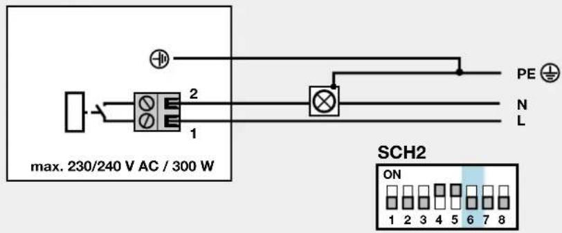
4.13 Connecting a warning light\* to the optional relay
A warning lamp with max. 230V\~/300W can be connected to the floating closing contact terminal 1 and 2 (KL1) of the optional relay (see figure 21). The warning light is on during every door cycle and flashes during the warning time of "automatic closing". Set DIP switch 6 (SCH2) to OFF.
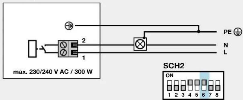
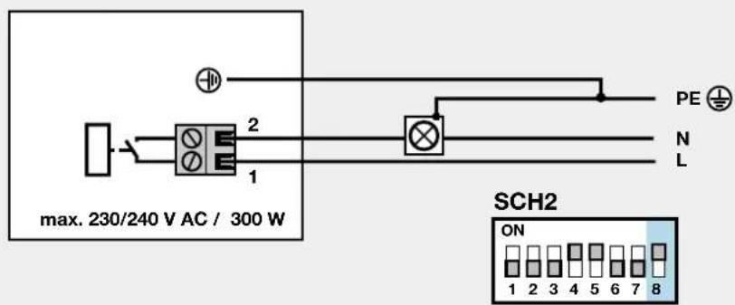
4.14 Connecting an external lamp to the optional relay
An additional external lamp with max. 230V\~/300W can be connected to the floating closing contact terminal 1 and 2 (KL1) of the optional relay (see figure 22). The lamp is switched parallel to the operator lighting. Set DIP switch 6 (SCH2) to ON.
4.15 Connecting a "door closed" display to the optional relay
An external “door closed” display with max. 230V\~/300W can be connected to the floating closing contact terminal 1 and 2 (KL1) of the optional relay (see figure 23). The optional relay is activated during the end-of-travel position “door closed”. Set DIP switch 8 (SCH2) to ON.
5 Special functions and any other adjustment possibilities of the garage door operator
5.1 Second opening position (airing position)
In the airing position a second opening position can be freely programmed. The latter is switched by channel 2 of the radio receiver. Terminal 20 (0 V) and 23 (impulse input partial opening). Set DIP switch 7 (SCH2) to OFF.
5.1.1 Programming the second opening position (airing position)
The operator is ready for use and the operator stands still. Check again if the guiding hitch is clutched in the flange lock / belt lock (see figure ).
1) Press the black button (for approx. 6 sec.) until the lamp starts flashing. Allow to flash twice, then press additionally the white button and press (for approx. 2 sec.) until the lamp quickly flashes twice. Then release both buttons.
2) Now press the white operating button so that the door can travel to its "Second opening" position. The door moves as long as the white button stays pressed (permanent contact). Once the button is released, the door stops immediately. The next time the button is pressed, the door travels in the opposite direction. This procedure is repeated until the desired "Second opening" position is reached.
3) Briefly press the black "learn" button. The operator lighting is switched on. "Second opening position" is now programmed.
5.2 Defined direction instructions
A defined direction option is adjustable through DIP switch 7 (SCH2).
1) radio channel 1 (terminal 20/21) = open - stop - open etc.
2) radio channel 2 (terminal 20/23) = closed - stop - closed etc.
3) Set DIP switch 7 (SCH2) to ON
5.3 Quick-opening function
The quick-opening function is selectable through DIP switch 3 (SCH2). Thereby: up to 50 % higher opening speed*.
1) Set DIP 3 (SCH2) to ON = quick-opening speed
2) Set DIP 3 (SCH2) to OFF = normal opening speed
* depending on the door
Note
The motor of the garage door operator is equipped with a thermal overload protection. In case of 2-3 quick door runs in "OPEN" position (max 40 sec.) within 2 minutes, this overload protection reduces the door speed, i.e. the door travels in direction "OPEN" and "CLOSED" have the usual speed. After a rest period of 2 additional minutes, the next run in direction "OPEN" is executed quickly.

ATTENTION: danger to life
This function is not to be selected for tipping and swing doors, but only for holohedrally closed sectional doors!
Note
After changing the door speed the operator has to be newly programmed!
5.4 Soft-stop
Soft-start is adjustable with DIP switch 4 (SCH2) before reaching end-of-travel position "CLOSED"
1) Set DIP 4 (SCH2) to ON = 30 % soft-stop – up and over door
2) Set DIP 4 (SCH2) to OFF = 50 % soft-travel speed
5.5 Short return to the position "door closed"
The short return to the position “door closed” is adjustable with DIP switch 5 (SCH2), i.e. the slide moves briefly to position “OPEN” when reaching “CLOSED”.
1) Set DIP 5 (SCH2) to ON = short return "long"
2) Set DIP 5 (SCH2) to OFF = short return "very short"
Note
If DIP5 is activated during the memorising process, the following functions are activated:
1) DIP5 (SCH2) set to ON = Short return "very short"
2) DIP5 (SCH2) set to OFF = Short reverse deactivated
On each new memorising process this procedure has to be repeated.
5.6 Automatic timer
With this function, the door is automatically closed after a preset open phase has elapsed. According to EN 12453
Tab.1, this function is only permitted if combined with a photocell.
Note
If the "automatic timer" is set, impulse operation is not possible. Each command causes the door to open or the open phase to be reset. A closing from the position "partial opening" occurs only if the distance to the end-of-travel position "door CLOSED" is >500 mm. In case of a smaller distance, the door has to be closed by reoperating the button "partial opening".
5.6.1 Programming the automatic timer / early warning phase
The door must be at a standstill and ready for operation. Briefly press the black "learn" button (lamp flashes five times), wait till the desired open phase is over (min. 10 sec. to max. 150 sec.). Then briefly press the black "learn" button, the lamp continues to flash five times. You must now wait for the early warning phase to be set (min. 3 sec. to max. 30 sec.), then briefly press the black "learn" button again. You have now activated the automatic timer. In this mode the door can only be opened via radio and button. If a command is given during the closing phase, the door reverses and travels to its "OPEN" position. Automatic closing only takes place from the "OPEN" position provided no safety circuit has been broken and the open phase has elapsed.
Note
If, on account of the overcurrent cutoff, the door has reversed twice to its "OPEN" end-of-travel position, the automatic timer will be blocked. The garage lighting signals the impulse code for "twice safety device" and an acknowledgement
via the button must be issued. The open phase will not start running until this acknowledgement has been issued.
5.6.2 Automatic timer "OFF"
Briefly press black "learn" button consecutively twice.
5.7 Light at "CLOSE"
If the lighting is to stay on even with the door closed, (operator lighting stays switched on for approx.150 sec. when door is closed) this can be achieved by the following action:
1) First unplug from the mains.
2) Press the black "learn" button and keep it pressed.
3) Plug back into the mains.
4) After the lamp has switched on, release the "learn" button.
On repeating the procedure, at the "CLOSE" position the light switches off again to 5 sec. lightning time.
6 Use of the garage door operator
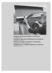
Only ever operate the garage door operator provided you have a full view of the door's area of movement. Wait until the door has come to a complete halt before entering the door's area of movement. Before driving in or out of the garage, always check that the door has fully opened!
Note
Initial function checks as well as programming or extending the remote control should always take place from inside the garage.
text_image
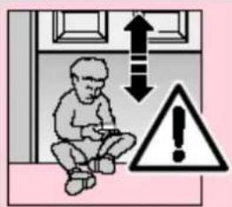
Safety warning illustration showing a child sitting inside a room with an upward arrow and warning symbolATTENTION
Keep hand transmitters out of the reach of children!
The function of the mechanical release should be checked every month. The pull cord with knob may only be actuated when the door is closed, otherwise with weak, broken or defective springs or due to inadequate counterbalancing, there is a risk that the door could close too quickly.

ATTENTION
Never hang bodily from the pull cord with knob!
text_image
STOP STOPAll persons using the door system must be shown how to operate the garage door operator properly and safely. Demonstrate and test the mechanical release as well as the safety return. To do this, halt the movement of the closing door by grasping it with both hands. The door system should gently cut-out and initiate the safety return. The same should happen during the
opening cycle, i.e. the door system gently cuts out and the door comes to a halt.
6.1 Normal operation
In the normal operation mode the garage door operator works entirely according to impulse repetition control, whereby it makes no difference whether an external button, a programmed-in hand transmitter button or the test button on the control PCB is pressed:
1st impulse: The door travels towards an end-of-travel position.
2nd impulse: the door stops.
3rd impulse: the door travels in the opposite direction.
4th impulse: the door stops.
5th impulse: the door travels in the direction of the end-of-travel position selected with the 1st impulse etc.
The operator lighting comes on when the door starts to move and automatically goes out 5 or 150 sec. later on completion of the cycle.
6.2 Operation following actuation of the mechanical/manual release
If, for instance due to a mains power failure, the mechanical release was actuated, the carriage must reengage in the door link latch before normal operation can be resumed:
1) Press the green button on the carriage (see figure 17).
2) Move the door manually until the carriage reengages in the door link latch.
3) Allow the door to complete several uninterrupted opening and closing cycles to check whether it has fully closed and fully opened.
The operator is now ready again to resume normal operation.
Note
If, after carrying out several interrupted door cycles, the behaviour of the door does not correspond to that described in stage 3, it will be necessary to rerun the learning procedure (see section 3.2.2).
6.3 Error messages operator lighting / LED-diagnosis
(Lighting diodes, see figure) Via the LED-diagnosis 3 and 4, which are visible after opening the transparent lid, causes for malfunctions can be easily identified. During the normal operation these LEDs are not lighting.
Lighting: flashes once within 1 second LED: 4 glows
Cause: A emergency-stop function connected to terminals 12 and 13 has been interrupted or activated (see section 4.8).
Remedy: The STOP or emergency-OFF circuit is to be closed.
Note: If a STOP or emergency-OFF circuit is not connected to terminals 12 and 13, check whether the DIP switch 1 (SCH1) is set at "ON".
Lighting: flashes once within 1 second LED: 4 flashes
Cause: A photocell connected to terminals 20 and 71 has been interrupted or activated (see section 4.9/4.10).
Remedy: Remove the obstruction causing the problem and/or check the photocell, if necessary replace.
| Note: If a STOP or emergency-OFF circuit is not connected to terminals 20 and 71, check whether the DIP switch 2 (SCH1) is set at "ON" and DIP switch 1 (SCH2) is set at "O F F". |
Lighting: flashes 1 x in 1 second
LED: 3 glows
Cause: A border protection (8,2kΩ)connected to terminals 20 and 74 has been interrupted or activated (see section 4.11).
Remedy: Remove the obstruction and/or check the border protection, if necessary.
Note: If no safety border is connected to terminals 20 and 74, check whether the DIP switch 3 is set at "OFF" and whether resistor 8,2kΩ is connected to terminals 20 and 74.
Lighting: flashes 1 x in 1 second
LED: 3 flashes
Cause: A border protection (optical) connected to terminals 20, 74 and 77 has been interrupted or activated (see section 4.12).
Remedy: Remove the obstruction and/or check the border protection, if necessary.
Note: If no safety border is connected to terminals 20, 74 and 77 check whether the DIP switch 3 is set at "OFF" and whether resistor 8,2kΩ is connected to terminals 20 and 74.
Lighting: flashes 2 x in 3 second
Cause: Due to an overcurrent cutoff, the operator has reversed twice to the "OPEN" end-of-travel position.
Remedy: Remove the obstruction. Check the door action and, if necessary, run through the learning procedure (see section 3.2.2).
Acknow-
| ledgement: | Generate another impulse via an external button, the radio receiver or the PCB |
| Note: | This error is only displayed if the automatic timer is set. |
Lighting: flashes 3 x in 4 seconds
Cause: Operator has not yet undergone the learning procedure (this is simply being brought to your attention, it does not constitute an error).
Remedy: Run through the learning procedure (section 3.2.2).
Lighting: flashes 4 x in 5 seconds
Cause: see section 6.4
Remedy: see section 6.4
Lighting: flashes 5 x in 6 seconds
Cause: Programming of the automatic timer has been started (this is simply being brought to your attention, it does not constitute an error).
Remedy: Run through the learning procedure (see section 5.6.1).
6.4 Measures following error message
Causes of possible error messages:
- The learned distance is too short, < 60 cm.
- During an automatic travel cycle when running through the learning procedure, the operating or "learn" button was pressed.
- During an automatic travel cycle when running through the learning procedure, the wicket door contact / photocell input was activated.
- The learning procedure has been started, but no button has been pressed within 60 seconds.
- The Hall sensor is defective.
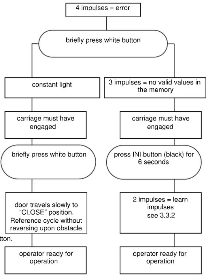
flowchart
graph TD
    A["4 impulses = error"] --> B["briefly press white button"]
    B --> C["constant light"]
    B --> D["3 impulses = no valid values in the memory"]
    C --> E["carriage must have engaged"]
    E --> F["briefly press white button"]
    D --> G["carriage must have engaged"]
    G --> H["press INI button (black) for 6 seconds"]
    F --> I["door travels slowly to "CLOSE" position. Reference cycle without reversing upon obstacle"]
    I --> J["operator ready for operation"]
    H --> K["2 impulses = learn impulses see 3.3.2"]
    K --> L["operator ready for operation"]
    J --> M["Operator ready for operation"]
6.5 Malfunction and remedy
If your garage door opener is malfunctioning, test the system according to the following checklist:

ATTENTION
Before carrying out any work on the operator with the cover removed, it is essential to unplug it from the mains!
6.5.1 Operator fails to start up
Check whether mains voltage is being supplied.
6.5.2 Operator fails to work with hand transmitter:
If the LED control light does not light up when the transmitter button is pressed, the battery voltage is too low. Replace the battery in the hand transmitter. If despite replacing the battery, the system still fails to work, check the hand transmitter or receiver.
6.5.3 Operator fails to work with externally connected buttons:
Check buttons, leads and connecting terminals.

ATTENTION External voltage not permitted.
6.5.4 Door does not close or open fully:
Door mechanics are stuck.
An obstruction is blocking the travel route.
Correct the door action or remove the obstruction.
Repeat learning procedure! See point 3.3.2.
6.5.5 Operator responds but door fails to open:
Check door latches and if necessary remove.
Transport carriage has not engaged with door link.
Check the emergency release.
6.5.6 Closing door changes direction:
Door mechanics are stuck.
An obstruction is blocking the travel route.
Correct door action or remove obstruction.
Repeat learning procedure in accordance with point 3.2.2.
6.5.7 Lighting is defective:
Unplug from mains.
Remove view panel.
Check whether the halogen lamp is securely plugged in.
Replace halogen lamp (G 4 / 10 W, clear).
6.5.8 Insufficient range of radio remote control:
Check hand transmitter battery.
Correct aerial routing.
7 Terms and Conditions of Warranty
Warranty period
Over and above the statutory guarantee provided by the dealer's Contract of Purchase, we grant the following warranty from the date of purchase:
a) 60 months for driving mechanics, motor and motor control
b) 24 months for radio system, radio system accessories and special accessories and devices
No warranty for use-up components (z.B.: batteries, light bulbs etc.)
Claims made under the warranty do not extend the warranty period. The warranty period for replacement parts and repair work is six months, at least, however, the initial warranty period.
Prerequisites
Warranty claims are only applicable in the country where the product was purchased. The product must have been purchased through our authorised distribution channels. The warranty only covers damage to the contract object itself. Reimbursement of expenses for dismantling and installing, inspecting corresponding components as well as claims for lost profits and damages are not covered by the warranty. The receipt of purchase substantiates your right to claim under the warranty.
Performance
During the warranty period we undertake to rectify any and all faults on the product which can be proved to be attributed to a material or manufacturing defect. We pledge to provide free of charge and at our discretion, parts and service labour to repair or replace any part of the product that fails due to a manufacturing defect, to exchange the defective merchandise for faultless merchandise or to grant a price reduction.
The warranty does not cover damage caused as a result of:
- improper installation and connection
- improper use, putting into service and operation
- external influences, such as fire, water, abnormal environmental conditions
- mechanical damage as a result of an accident, a fall or impact
- negligent or wanton destruction
- normal wear and tear
- repairs carried out by non-qualified persons
- using parts of another manufacturer
- removing the product number or making it unidentifiable
Replaced parts become our property.
8 Technical Data
Power supply: 230/240 V, 50/60 Hz Standby approx. 1 W
Protection category: For dry rooms only
Automatic cutout: Is automatically programmed separately for both operational d i r e c t i o n s .
End-of-travel Self-learning, non-wearing, cutoff / Force limit: since no mechanical switches
are used, additionally integrated
excess travel stop of approx.
s. Automatic cutout readjusts
itself during each door cycle.
Push and pull force: see type plate
Motor: DC motor with Hall sensor
Transformer: with thermal overload protection
Connection: Connection technique without screws for external equipment with safe low voltage of 24 V DC,
e.g. internal and external buttons for i m p u l s e
Special functions: - Operator lighting
- STOP/cutout switch can be connected
- Photocell, lockable
- border protection 8,2kΩ can be connected
- border protection (Fraba) can be connected
- warning light 230 V AC can be connected
- Options relay for connecting an e x t e r n a l
| Quick release: | In the event of a power failure,actuated from the inside via ap u l l c o r d | ||||
| Remote control: | 4-button hand transmitter | |||
| RCBE | 868/4 | (868.360 MHz) | ||
| and | separate | receiver. | ||
| Universal fitting: | for up-and-over and sectional doors |
| Door speed: | approx. 135 mm/s (depending on size and weight of door) |
| Airborne emission | noise Garage |
| door operator: | ≤ 70 dB (A) |
| Boom: | Extremely flat (no more than 30 mm high) with integral door security kit. Boom in toothed belt or synthetic belt version. |
9 Dismantling and Disposal
Please note that should dismantling become necessary, the safety regulations apply here also and must be observed accordingly. Disposal must be carried out in accordance with the respectively applicable regulations concerning the disposal of scrap.
Subject to technical changes!
Issue: May 2008
10 Circuit board overview and short instructions of programming
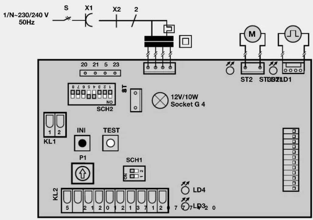
text_image
1/N~230/240 V 50Hz S X1 X2 2 20 21 5 23 ST 12V/10W Socket G 4 M ST2 ST39ZLD1 KL1 INI TEST P1 SCH1 KL2 LD4 77LD32 0

(factory setting)

(factory setting)
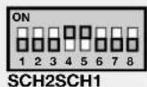
| DIP-switches functions (SCH1) | ON | OFF |
| 1: Stop-button | no | yes |
| 2: Light barrier | no | yes |
| LED Display | glows | flashes |
| LED 1 (red) | Motor goes to "CLOSE" | -- |
| LED 2 (green) | Motor goes to "OPEN" | -- |
| LED 3 | 8,2kΩ-barth activated | OS-barth activated |
| LED 4 | Stop circuit interrupted | Light barrier activated |
| DIP-switches functions (SCH2) | ON | OFF |
| 1: Light barrier | 2-wire | Contact |
| 2: Evaluation protection of closing borders | OS | 8,2kΩ |
| 3: Quick-opening | yes | no |
| 4: Soft-stop | 30% 50% | |
| 5: Short return to the position "door CLOSED" | long | short |
| 6: External light: light function (1), warning function (2) | 1 | 2 |
| 7: Defined direction instructions | yes | no |
| 8: Light at "CLOSED" | yes | no |
Brief instructions learning procedure:
- Press the black button until the lamp starts flashing. Allow to flash twice, then release the "learn" button.
- Press white operating button until door travels to its "OPEN" position (permanent contact).
- Briefly press black button.
- Door closes, opens and closes twice automatically. The operator is now programmed.
Programming operator light at door closed, duration 150 sec.:
- Unplug from the mains.
- Press black button drücken (permanent contact).
- Plug back into the mains while keeping "learn" button pressed.
- After the operator lamp has switched on, release the "learn" button. On repeating the procedure the factory settings ("door closed" = 5 sec.) are active again.
Brief instructions second opening position:
- Press the black button until the lamp starts flashing twice.
- Additionally press the white button until the lamp flashes more quickly, the release both buttons.
- Open the door with the white button (permanent contact) until the desired "second opening" position is reached.
- Briefly press the black button. The "second opening" position is programmed.
Programming automatic timer / early warning phase
- Briefly press black button. Lamp flashes 5 times.
- Wait till the desired open phase is over (max. 150 sec.), then briefly press black button.
- Wati for early warning phase to be set (3-30sec.). The lamp flashes beyond 5x. Then again press black button.
- Automatic timer / early warning phase has now been programmed.
To switch out the automatic closure briefly press black button consecutively.