GA101 - Garage door BERNER - Free user manual and instructions
Find the device manual for free GA101 BERNER in PDF.

Frequently Asked Questions - GA101 BERNER
User questions about GA101 BERNER
0 question about this device. Answer the ones you know or ask your own.
Ask a new question about this device
Download the instructions for your Garage door in PDF format for free! Find your manual GA101 - BERNER and take your electronic device back in hand. On this page are published all the documents necessary for the use of your device. GA101 by BERNER.
USER MANUAL GA101 BERNER
Installation, Operating and Maintenance Instructions
Garage Door Operator
B Required Tools for Installation 2
1 IMPORTANT NOTES 7
1.1 Important safety instructions 7
1.1.1 Warranty 7
1.1.2 Checking the door / door system 7
1.2 Important instructions for safe installation 7
1.2.1 Before installing the garage door operator 7
1.3 Warnings 8
1.4 Maintenance advice 8
1.5 Information on the illustrated section 8
Illustrated Section 15-29
2 DEFINITIONS 39
3 PREPARING FOR INSTALLATION 39
3.1 Required clearance for installing the operator 39
3.1.1 Before installing the boom 39
3.1.2 Boom operating modes 39
3.1.3 Manual operation 39
3.1.4 Automatic operation 40
3.2 Installing the garage door operator 40
3.2.1 Centrally positioned lock on a sectional door 40
3.2.2 Off-centred reinforcement profile on a sectional door 40
3.2.3 Tensioning the toothed belt 40
3.2.4 Establishing the door's end-of-travel positions by installing the limit stops 40
3.3 Electrical connection 40
3.3.1 Connecting additional components 41
3.3.2 Connecting external IMPULSE buttons to start or stop travel cycles 41
3.3.3 Connecting an additional external radio receiver 41
3.3.4 Connecting a 2-wire photocell 41
3.3.5 Connecting a wicket door contact 41
3.3.6 Connecting the options relay PR 1 41
3.3.7 Emergency accumulator 41
4 PUTTING THE OPERATOR INTO SERVICE 41
4.1 Preparation 41
4.2 删除的 door data 41
4.3 Learning cycles 41
4.4 Setting the forces 42
4.5 Radio receiver 42
4.5.1 Integral radio module 42
4.5.2 Connecting an external radio receiver 42
4.5.3 删除的data of the internal radio module 42
4.6 Setting the DIL-switches 42
4.6.1 Automatic timer 42
4.6.2 CLOSE end-of-travel signalling DIL-switch A OFF / DIL -switch B ON 43
4.6.3 Advance warning phase DIL-switch A ON / DIL -switch B OFF 43
4.6.4 External lighting DIL-switch A OFF/DIL-switch B OFF 43
4.6.5 Door type DIL-switch C 43
4.6.6 Photocell DIL-switch D 43
4.6.7 Stop / static current circuit with self-monitoring DIL-switch E 43
4.6.8 Door maintenance indication DIL-switch F 43
5 USING THE GARAGE DOOR OPERATOR 43
5.1 Normal operation 43
5.2 Power failure backup with the emergency accumulator 44
5.3 Operation after actuating the mechanical release 44
6 CHANGING THE LIGHT BULB 44
7 SIGNALS FROM OPERATOR LIGHTING WHEN MAINS POWER ON 44
8 ERROR MESSAGES
9 DISMANTLING 45
10 OPTIONAL ACCESSORIES (NOT INCLUDED IN THE SCOPE OF SUPPLY) 45
11 TERMS AND CONDITIONS OF THE WARRANTY 45
12 TECHNICAL DATA 45
Dear Customer,
Thank you for choosing this quality product from our company. Please keep these instructions safe for later reference!
Please carefully read and follow these instructions. They provide you with important information on the safe installation, operation and correct care / maintenance of your garage door operator, thus ensuring that this product will give you satisfaction for many years to come.
Please observe all our safety notes and warnings, specifically headed ATTENTION, CAUTION or Note.
1 IMPORTANT NOTES

ATTENTION
Installation, maintenance, repair and dismantling of the garage door operator may only be carried out by specialists.
Note
The inspection log book and instructions for safe handling and maintenance of the door system must be placed at the disposal of the end user.
1.1 Important safety instructions

CAUTION
Incorrect installation or handling of the operator could result in serious injury. For this reason, it is important to follow all the instructions in this manual.
This garage door operator is designed exclusively for impulse operation of spring-balanced up-and-over and sectional doors in the non-commercial sector. Use in the commercial sector is not permitted!
Please observe the manufacturer's specifications regarding the door and operator combination. Possible hazards as defined in EN 12604 and EN 12453 are prevented by the design itself and by carrying out installation in accordance with our guidelines. Door systems used by the general public and equipped with a single protective device, e.g. force limit, may only be used when monitored.
1.1.1 Warranty
We shall be exempt from our warranty obligations and product liability in the event that the customer carries out his own structural changes or undertakes improper installation work or arranges for same to be carried out without our prior approval and contrary to the installation guidelines we have provided. Moreover, we shall accept no responsibility for the inadvertent or negligent operation of the operator and accessories nor for the improper maintenance of the door and its counterbalance mechanism. Batteries and light bulbs are also not covered by the warranty.
Note
Should the garage door operator fail, a specialist must be immediately entrusted with its inspection / repair.
The design of the operator is not suitable nor intended for the opening and closing of heavy doors, i.e. doors that are difficult or impossible to open and close manually. Before installing the operator, it is therefore necessary to check the door and make sure that it can also be easily moved by hand.
To do this, raise the door approx. 1 metre and then let it go. The door should retain this position, moving neither up nor down. If the door moves in any of the two directions, there is a risk that the compensating springs are defective or incorrectly adjusted. In this case increased wear and malfunctioning of the door system can be expected.
CAUTION: Danger!
Do not attempt to change, re-adjust, repair or move the compensating springs for the door's counterbalance mechanism or their holders. The springs are under considerable tension and can cause serious injury. In addition, check the entire door system (pivots, door bearings, cables, springs and fastenings) for wear and possible damage.
Check for signs of corrosion or fractures. The door system may not be used if repair or adjustment work needs to be carried out. Always remember that a fault in the door system or a misaligned door can also cause severe injury.
Note
Before installing the operator, and in the interests of your own safety, make sure that any work needed on the door's compensating springs is carried out by a qualified garage door specialist. Only correct fitting and maintenance in compliance with the instructions by a competent / specialist company or a competent / qualified person ensures safe and flawless operation of the system.
1.2 Important instructions for safe installation
The specialist carrying out the work must ensure that installation is conducted in compliance with the prevailing national regulations on occupational safety and those governing the operation of electrical equipment. In the process, the relevant national guidelines must be observed.
Possible hazards as defined in DIN EN 13241-1 are prevented by the design itself and by carrying out installation in accordance with our guidelines. Any further processing must ensure that the national regulations governing the operation of electrical equipment are complied with.
1.2.1 Before installing the garage door operator, check that the door is in a flawless mechanical condition and is correctly balanced, so that it can be easily moved by hand (EN 12604). Further check whether the door opens and closes in the proper manner (see section 1.1.2). In addition, any of the door's mechanical locks and latches not needed for power operation of the garage door should be immobilized. Included here in particular are the latching mechanisms of the door lock (see section 3.2.1/3.2.2).
The garage door operator is designed for use in dry buildings and therefore may not be installed outdoors. The garage ceiling must be constructed in such a way as to guarantee safe, secure anchoring of the operator. In the case of ceilings that are too high or too lightweight, the operator must be attached to additional braces.
Note
The installer must check that the fitting materials supplied are suitable for the purpose and intended place of installation.
The clearance between the highest point of the door and the ceiling (also when the door is opening) must be at least 30mm (see figure 1.1a/1.1b). If there is inadequate clearance, the operator may also be installed behind the opened door, provided sufficient space is available. In these instances, an extended door link (to be ordered separately) must be used. The garage door operator can be positioned off-centre by a maximum of 50~cm . The exception being sectional doors with high-lift tracks (track application "H"), where a special track fitting is required. The required shockproof electric socket allowing the operator to be connected to the electricity supply should be installed at a distance of approx. 50~cm from the operator head. Please check these dimensions!
Note
A sign warning about the trap hazard must be permanently affixed at a conspicuous location or in the proximity of the permanently installed push Buttons used to operate the door.
1.3Warnings
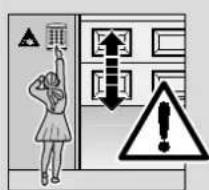
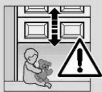
Permanently installed controls (such as push Buttons, switches etc.) have to be installed within sight of the door but well away from any moving parts at a height of at least 1.5m . It is vital that they are installed out of the reach of children!
Make sure that
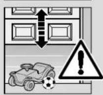
- neither persons nor objects are located within the door's range of travel.
- children do not play around with the door system!
the rope of the mechanical release on the carriage cannot become entangled in the ceiling's support system or in any other protruding parts of vehicles or the door.
NTION
For garages without a second access door, an emergency release must be fitted to ensure that there is no danger of getting locked out. This must be ordered separately and its function checked once a month.

ATTENTION
Do not allow anyone to hang bodily from the release pull rope with knob!
1.4 Maintenance advice
The garage door operator is maintenance-free. For your own safety, however, we recommend having the door system checked by a specialist in accordance with the manufacturer's specifications. Inspection and maintenance work may only be carried out by a specialist. In this connection, please contact your supplier. A visual inspection may be carried out by the owner.
If repairs become necessary, please contact your supplier. We would like to point out that any repairs not carried out properly or with due professionalism shall render the warranty null and void.
1.5 Information on the illustrated section
The illustrated section shows installation of the operator on an up-and-over door. Where installation differs for a sectional door, this is shown in addition. In this instance, letters are assigned to the figures as follows:
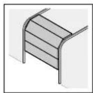
a) to the sectional door and
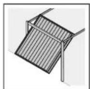
b to the up-and-over door.
Some of the figures additionally include the symbol shown below, offering a text reference. These references to specific texts in the ensuing text section provide you with important information regarding installation and operation of the garage door operator.
Example:

= see text section, point 2.2
In addition, in both the text section and the illustrated section at the points where the DIL-switches of the operator are explained, the following symbol appears to indicate a factory setting or settings.

= This symbol indicates the factory setting/s of the DIL-switches.
Copyright.
No part of this instruction manual may be reproduced without our prior permission. Subject to changes.
TABLE DES MATIERES
PAGE
A Articles livres
2
Waiting phase at the OPEN end-of-travel position before the door closes using the automatic timer.
Automatic timer
Automatic timed closing of the door from the OPEN end-of-travel position, following elapse of a set phase.
DIL-switches
Switches on the control unit circuit board for setting the controls.
Photocell
When the photocell safety device is activated, a closing door stops and reverses. The hold-open phase starts afresh.
Impulse controls
A sequence of impulses allowing the door to alternately OPEN-STOP-CLOSE-STOP.
Force-learning cycle
During a learning cycle the necessary forces are learned.
Normal cycle
Door travels applying the learned distances and forces.
Reference cycle
Door travels in the OPEN direction in order to lay down the standard setting.
Reversing cycle
Door travels in the opposite direction on activation of the safety devices, up to the OPEN end-of-travel position.
Reversing limit
The reversing limit separates the area between the returning or stopping of the door when the force is cut-off.
Distance-learning cycle
During a learning cycle the necessary distances are learned.
Advance warning phase
The time between the travel command and the start of travel.
Factory reset
Resetting the learned values to the ex factory setting.
3 PREPARED FOR INSTALLATION
Before installing the operator and in the interests of personal safety, make sure that any necessary repairs to the door are carried out by a qualified service engineer.
Only correct fitting and maintenance in compliance with the instructions by a competent / specialist company or a competent / qualified person ensures safe and flawless operation of the system.
The specialist carrying out the work must ensure that installation is conducted in compliance with the prevailing national regulations on occupational safety and those governing the operation of electrical equipment. In the process, the relevant national guidelines must be observed.
Possible hazards as defined in DIN EN 13241-1 are prevented by the design itself and by carrying out installation in accordance with our guidelines.
Note
The function of all safety and protective devices should be tested once a month, during which time any detected faults or defects should be rectified immediately.

ATTENTION
Only ever operate the garage door when you have full view of the movement range of the door. Before driving in or out of the garage, always check that the door has fully opened. You must never drive or walk through the entrance to the garage unless the door has reached the OPEN end-of-travel position. In addition, check the entire door system (door pivots, bearings and fastenings) for wear and possible damage. Check for signs of corrosion or fractures. The door system may not be used if repair or adjustment work needs to be carried out. Always remember that a fault in the door system or a misaligned door can cause severe injury.
All persons using the door system must be shown how to operate it properly and safely. Demonstrate and test the mechanical release as well as the safety return. To do this, halt the closing door by grasping it with both hands. The door system must initiate the safety return.
Prior to installation, any of the door's mechanical locks and latches not needed for power operation of the door should be immobilized and, if necessary, removed entirely. This includes in particular any locking mechanisms connected with the door lock. In addition, check that the door is in a flawless mechanical condition, so that it can be easily operated by hand and allows itself to open and close properly (EN 12604).
3.1 Required clearance for installing the operator
The clearance between the highest point of the door and the ceiling (also when the door is opening) must be at least 30mm (see figure 1.1a/1.1b). Please check these dimensions! On a sectional door the mechanical latch must be completely dismantled (see figure 1.2a/1.3a).
3.1.1 Before installing the boom
Note
Before mounting the boom to the lintel or ceiling, push the carriage in the engaged state (see section 3.1.4) approx. 20~cm from the "OPEN" end-of-travel position. It is no longer possible to do this with the carriage engaged, once the limit stops and the operator have been installed (see figure 2.1).
3.1.2 Boom operating modes
The boom allows two different operating modes:
3.1.3 Manual operation (see figure 4.1)
The carriage is disengaged from the belt lock; i.e. the door is not directly connected to the operator enabling the door to be moved by hand. To disengage the carriage, the rope of the mechanical release must be pulled.
Note
If on disengagement the carriage is at the CLOSE end-of-travel position, the rope of the mechanical release must be pulled and remain so until the carriage has been moved so far along the boom that it can no longer hook into the limit stop (carriage travels a distance of approx. 3 cm). To be able to permanently operate the door manually, the rope must be fixed on the carriage as shown in figure 4.2.

ATTENTION
If in countries in which the European Standard EN 13241-1 must be complied with, the garage door operator is retrofitted by a specialist to a Hörmann sectional door without spring breakage safety device (Series 30), the responsible installer must also install a retrofit kit to the carriage. This kit comprises a screw to secure the carriage against inadvertent disengagement and a new pull rope sign, showing how to use the kit and carriage in the two boom operating modes.
3.1.4 Automatic operation (see figure 6)
The belt lock is engaged in the carriage, i.e. the door and the operator are connected to each other, thereby allowing power operation of the door.
To prepare the carriage for engagement, the green button must be pressed. The door must be allowed to travel in the direction of the carriage until the belt lock engages into it.

CAUTION
Do not insert fingers into the boom while the door is moving Risk of trapped fingers!
3.2 Installing the garage door operator

ATTENTION
When installing the operator, the pull rope must be removed (see figure 1.2a)
Note
Always cover over the operator before drilling, since drilling dust and shavings can lead to malfunctions.
3.2.1 Centrally positioned lock on a sectional door
For sectional doors with a centrally positioned lock/handle, fit the lintel bracket and the door link bracket off-centre (see figure 1a).
3.2.2 Off-centred reinforcement profile on a sectional door
In the case of an off-centred reinforcement profile on a sectional door, fit the door link bracket to the nearest reinforcement profile on the left or right (see figure 1.5a).
Note
Contrary to the illustrated section, for timber doors use 5 × 35 wood screws from the pack of screws supplied with the door (3 mm Ø drill hole).
The mechanical locks and latches on the up-and-over door must be put out of operation (see figure 1.3a). On the door models not listed here, the catches and latching mechanisms must be immobilized on site (see figure 1.2b/1.3b/1.4b).
Note
Contrary to the illustrated section (see figures 1.5b/1.6b), for doors with an ornamental wrought iron handle attach the lintel bracket and door link bracket off-centre.
For N80 doors with timber infill, the lower holes in the lintel bracket have to be used for installation (see figure 1.6b).
Note
If you are unable to push the door manually into the desired OPEN or CLOSE end-of-travel positions, this indicates that the door mechanics are too sluggish to be used with the garage door operator and must therefore be checked (see section 1.1.2)!
3.2.3 Tensioning the toothed belt
The toothed belt of the boom is already set at the factory for optimum tension. During the starting and braking phases of large doors it can happen that the belt hangs out of the boom profile temporarily. This, however, is of no technical disadvantage nor does it have any negative effect on the operator's function and service life.
3.2.4 Establishing the door's end-of-travel positions by installing the limit stops (see figure 5.1)
1) Insert the limit stop for the OPEN end-of-travel position loosely into the boom between the carriage and the drive unit and after installing the door link push the door by hand into the OPEN end-of-travel position. In doing so, the limit stop is pushed into the correct position. Then fix the limit stop for the OPEN end-of-travel position.
Note
If in the OPEN end-of-travel position the door does not reach the full passage height, the limit stop can be removed so that the integrated limit stop (in the operator head) is used.
2) Insert the limit stop for the CLOSE end-of-travel position loosely into the boom between the carriage and the door (see figure 5.2) and push the door by hand into the CLOSE end-of-travel position. In doing so, the limit stop is pushed close to its correct position. When the CLOSE end-of-travel position has been reached, move the limit stop approx. 1cm further towards the CLOSE end-of-travel position, then fix it in place (see figure 5.2).
3.3 Electrical connection
Notes on work involving electronics and electronics

ATTENTION
The following points apply to all work involving electrics / electronics:
- Electrical connections may only be made by a qualified electrician!
- On-site electrical installation must comply with the relevant safety regulations (230/240 V AC, 50/60 Hz)!
- Before working on the operator, always unplug from the mains first!
- External voltage at any terminals of the control system will completely destroy the electronics! To avoid malfunctions, ensure that the control cables of the operator (24 V DC) are laid in an installation system separate to the other supply lines (230 V AC)!
3.3.1 Connecting additional components
In order to connect additional components, the flap of the operator cover must be opened (see figure 3). The terminals to which the radio receiver or additional components (such as floating internal and external push-button units, OFF-switches or a wicket door contact as well as safety devices such as photocells) are connected, carry a safe low voltage of max. 30VDC only.
All the terminals can be multiple-assigned, however, max.
1 x 2.5 mm² (see figure). Always pull out the mains plug before connecting.
Note
The voltage of approx. +24V available at the connecting terminals cannot be used to supply power to a light!
3.3.2 Connecting external IMPULSE buttons to start or stop door travel cycles
One or more buttons with closer contacts (floating), e.g. internal push-button units, key switches, can be connected in parallel (see figure 10/11).
3.3.3 Connecting an additional external radio receiver*
In addition to or in place of an integral radio module (see section 4.5.2), an external radio receiver can be connected for the impulse function. The receiver plug is inserted into the corresponding module slot (see figure 12).
3.3.4 Connecting a 2-wire photocell*
2-wire photocells must be connected as shown in figure 13.
Note
When installing a photocell, ensure that the transmitter and receiver housing are mounted as close to the floor as possible - see instructions supplied with the photocell.
3.3.5 Connecting a wicket door contact*
Connecting a self-monitoring wicket door contact (must be with forced opening). Wicket door contacts must be connected as shown in figure 14.
Note
By opening the contact any possible travel cycles are immediately halted and permanently prevented.
3.3.6 Connecting the options relay PR 1*
The options relay PR1 can be used for CLOSE end-of-travel signalling and the light control. Connection as shown in figure 15.
3.3.7 Emergency accumulator*
To be able to operate the door in the event of a power failure, an optional emergency accumulator can be connected (see figure 21). In the event of a power failure, change over to accumulator operation takes place automatically. During accumulator-powered operation, the operator light remains switched off.
4 PUTTING THE OPERATOR INTO SERVICE
General notes
The operator features a memory (fail-safe even in the event of a power failure) where the door-specific data (distance of travel, forces necessary for door movement etc.) acquired during the learning process is stored and updated during subsequent travel cycles. This data applies to this particular door only. If another door is being used or if the running action of the door has greatly changed (e.g. limit stops subsequently adjusted or new
springs fitted etc.), then the data must be deleted and the operator must repeat the learning process.
Note
Before initial operation, check that all the connecting leads are correctly attached to the connecting terminals.
4.1 Preparation
The disengaged carriage must be prepared for engagement by pressing the green button on the carriage (see figure 6). The door must be moved manually until the carriage engages into the belt lock.
- insert the mains plug
the operator light flashes twice (see figure 18).
4.2 Deleting the door data
In the ex-factory state, the door data is deleted, so the operator is ready for the learning process immediately. In the case of a re-installed operator, the door data must first be deleted.
If it is necessary for the operator to repeat the learning process, the door data can be deleted as follows (see figure 17):
- Unplug from the mains.
- Press the button "T" in the housing and keep it depressed.
- Re-insert the mains plug and keep the above-mentioned button depressed until the operator light flashes once. The door data has been deleted. You can now proceed with the learning process.
4.3 Learning cycles
Note
The operator light flashes throughout the entire learning process.
Press the button "T" on the operator control system (see figure 18). A reference cycle in the opening direction is carried out up to the end stop. The operator stays at the OPEN end-of-travel position.
The next travel impulse causes the following steps to be automatically carried out:
- Learning the length of the door: a distance-learning cycle in the CLOSE direction up to the limit stop at decreasing speed.
- A travel cycle in the OPEN direction
- Learning the forces: a force-learning cycle in the CLOSE direction at normal speed
- A travel cycle in the OPEN direction
After the operator has performed the learning cycles, it stays at the OPEN position with the operator light ON.
The operator has now completed the learning process and is ready for operation.
Note
If the operator stalls with the operator light flashing or fails to reach the limit stops, the maximum forces have been set too low and must be re-adjusted (see section 4.4). A further travel impulse starts the entire learning process afresh.
Note
If the OPEN limit stop has not been reached, then the OPEN maximum force is set too low and must be increased. (see section 4.4). After increasing the OPEN maximum force (max. 1/8th rotation per setting attempt!), press the plate button "T" to allow the door to travel to the CLOSE end-of-travel position. Stop the door closing before it reaches the CLOSE end-of-travel position by pressing the button again. Then operate the door to travel to the OPEN position.
Note
If the CLOSE limit stop has not been reached, then the CLOSE maximum force is set too low and must be increased (see section 4.4). After increasing the maximum CLOSE force (max.
1/8th rotation per adjustment attempt!), delete the door data (see section 4.2) and repeat the learning process.
Note
Check the learned force limit by following the corresponding safety instructions provided in section 4.4!
The learning process can be interrupted at any time by a travel impulse. A further travel impulse starts the entire learning process afresh.
4.4 Setting the forces
The required forces for opening and closing the door which were learned and stored during the learning process are updated also during the subsequent travel cycles. That's why in the event that the running action of the door gets increasingly sluggish (e.g. spring tension slackens) it is important for safety reasons that these values do not reset themselves indefinitely, as any necessary manual operation of the door could otherwise pose a possible safety risk (e.g. door could drop down).
That's why the maximum forces available for opening and closing the door are pre-set at the factory (potentiometer at intermediate setting) but these can be increased if needed.
Note
The maximum forces set at the potentiometer have a slight effect on the sensitivity of the force limit, since the forces actually needed were stored during the learning process. The factory-set forces are suitable for the operation of standard doors.
For setting the maximum opening and closing forces, a potentiometer is available for each direction, accessible on removing the vision panel and marked P1 and P2 (see figure 19). The maximum force in the OPEN direction can be set via potentiometer P1; while the maximum force in the CLOSE direction can be set via potentiometer P2. In doing so, turning clockwise increases the forces, while turning anticlockwise reduces the forces.
Note
It is only necessary to increase the maximum forces preset at the factory (potentiometer at intermediate setting) should the need arise during the learning process (see section 4.3).

CAUTION: Danger!
The force should not be set higher than necessary, as this can cause injury to persons and/or damage to the door.
Setting the potentiometer too high can result in serious injury!
4.5 Radio receiver
4.5.1 Integral radio module
With an integral radio module, a maximum of 6 different hand transmitters can be programmed for the "impulse" If nforectian(OPEN-STOP-CLOSE-STOP).
hand transmitters are programmed, the first hand transmitter programmed is automatically deleted.
Note
The distance between the hand transmitter and the operator should be at least 1m
Programming the hand transmitter buttons
Briefly press button P on the operator cover. The red LED starts to flash. During this time the desired hand transmitter button can be registered. To do this, press the hand transmitter button until the red LED flashes rapidly. Release the hand transmitter button - this is now stored in the operator (see figure).
4.5.2 Connecting an external radio receiver*
In place of an integral radio module, an external radio receiver can be used for the "impulse" function. The plug of this receiver is inserted into the corresponding module slot (see figure).
In order to put the external radio receiver into service, it is essential to delete the data of the integral radio module.
4.5.3 Deleting the data of the internal radio module
Press button P on the control board and keep it pressed. The red LED flashes and signals that the unit is ready for the deletion process. The LED now flashes more rapidly. Afterwards, the data of the programmed hand transmitter buttons are deleted.
Note
Initial function checks as well as programming or extending the remote control should always take place from inside the garage.

CAUTION
Hand transmitters should be kept out of the reach of children and may only be used by persons who have been shown how to operate the remote-controlled door system. It is a general principle that the hand transmitter
should only be operated within sight of the door. Never drive or walk through a door opening unless the door has reached the OPEN end-of-travel position.
4.6 Setting the DIL-switches
The DIL-switches A to F (accessible on opening the flap in the operator cover, see figure) should be set in accordance with the national requirements, the required safety devices and the given local conditions.
The DIL switch settings may only be altered when the operator is at rest and the advance warning phase /automatic timer is inactive.
4.6.1 Automatic timer
DIL-switch A > ON / DIL-switch B > ON (see figure 1)
Operator function:
Automatic timed return following the hold-open phase and advance warning phase from the OPEN end-of-travel position.
Operator lighting:
-Flashes rapidly during the advance warning phase.
-Glows constantly when the door is moving and throughout the holdopen phase.
Options relay function: - Clocks rapidly throughout the advance warning phase and slowly when the door is moving, continued contact during the hold-open phase
Note
The automatic timer may only be activated within the scope of DIN EN 12453 provided a safety device is connected.
Note
To be able to set the automatic timer, the photocell must be activated. For this, set DIL-switch D to ON.
After reaching the OPEN end-of-travel position, the automatic timer starts once the hold-open phase has elapsed. After generating an impulse, walking or driving past the photocell, the hold-open phase is automatically extended by 30 s.
4.6.2 CLOSE end-of-travel signalling
DIL-switch A OFF/DIL-switch B ON
(see figure 16.2)
Operator lighting: - Permanent light while the door is moving / persistence time after CLOSE end-of-travel position
Options relay function: - CLOSE end-of-travel signalling
4.6.3 Advance warning phase
DIL-switch A ON/DIL-switch B OFF
(see figure 16.3)
Operator lighting: - Advance warning phase, flashing rapidly
- Permanent light while the door is moving
Options relay function: - Clocks slowly while the door is moving (function of a self-flashing warning light).
4.6.4 External lighting
DIL-switch A OFF/DIL-switch B OFF
(see figure 16.4)
Operator lighting: - Permanent light while the door is moving / persistence time after CLOSE end-of-travel position
Options relay function: - Same function as operator lighting (external lighting)
4.6.5 Door type
DIL-switch C (see figure 16.5
ON up-and-over door, long "soft" stop ramp
OFF sectional door, short "soft" stop ramp
4.6.6 Photocell
DIL-switch D (see figure 16.6)
ON activated, after the photocell has been activated, the door reverses to the OPEN end-of-travel position
OFF activated, automatic timed closing not possible (DIL-switch A/B)
4.6.7 Stop / static current circuit with self-monitoring
DIL-switch E (see figure 16.7)
ON activated, for wicket door contact with self-monitoring
OFF activated
Note
Safety devices without self-monitoring must be tested every 6 months.
4.6.8 Door maintenance indication
DIL-switch F (see figure 16.8
ON activated, if the maintenance cycle has been exceeded, this is indicated by the operator lighting flashing several times after each completed travel cycle.
OFF activated, no signal is given if the maintenance cycle has been exceeded.
The maintenance interval is arrived at when the operator has been in service for more than a year since the last learning process, or the operator has completed or exceeded 2000 closing cycles.
Note
The maintenance data is reset by repeating the learning process (see section 4.3).
5 USING THE GARAGE DOOR
Only ever actuate the garage door operator provided you have full view of the movement range of the door. Wait until the door has come to a complete standstill before entering the movement range of the door! Before driving in or out of the garage, always check that the door has opened fully.

ATTENTION
Never hang bodily from the pull rope with knob!
Note
All persons using the door system should be shown how to operate the garage door operator properly and safely. Demonstrate and test the mechanical release as well as the safety return. To do this, halt the closing door by grasping it with both hands. The door system should gently cut out and initiate the safety return. The same should happen during the opening cycle, i.e. the door system gently cuts out and the door comes to a halt.
5.1 Normal operation
In the normal operation mode the garage door operator works exclusively by impulse sequential control, whereby it makes no difference whether an external push-button, a programmed hand transmitter button or the circuit board button is pressed:
- Impulse: door travels towards an end-of-travel position
- Impulse: door stops
- Impulse: door travels in the opposite direction
- Impulse: door stops
- Impulse: door travels towards the end-of-travel position selected with the 1st impulse etc.
The operator lighting comes on when the door starts to move and automatically goes out when the cycle is completed.
5.2 Power failure backup with the emergency accumulator*
To be able to operate the door in the event of a power failure, an optional emergency accumulator can be connected (see figure 21). In the event of a power failure, the change over to accumulator operation takes place automatically. Throughout accumulator-powered operation, the operator lighting stays off.
Note
Only the specifically designated emergency accumulator with integral charging circuit may be used.
5.3 Operation after actuating the mechanical release
If the mechanical release was actuated, e.g. due to a power failure, the carriage must be re-engaged in the belt lock before normal operation can be resumed:
- Move the operator until the belt lock in the boom is well accessible for the carriage, and then stop the operator.
- Press the green button on the carriage (see figure 6).
- Move the door manually until the carriage re-engages in the belt lock.
- Carry out several uninterrupted travel cycles to check whether the door has fully reached its closed position and whether it has also fully opened (the carriage comes to a halt shortly before the OPEN limit stop).
- The operator is now ready to resume normal operation.
Note
The function of the mechanical release should be checked once a month. The pull rope with knob may only be actuated when the door is closed, otherwise, in the case of weak, broken or defective springs or due to an inadequate counterbalance, there is a risk that the door could close too quickly.

CAUTION
Never hang bodily from the pull rope with knob!
6 CHANGING THE LIGHT BULB
When changing the light bulb, the bulb must be cold and the door closed.
-
Pull out the mains plug
-
Change the bulb 24V / 10W B(a) 15 s (see figure 22)
- Re-insert the mains plug
The operator lighting flashes four times
7 SIGNALS FROM OPERATOR LIGHTING WHEN MAINS POWER ON
When the mains plug is inserted, without the circuit board button "T" (with opened vision panel) being pressed, the operator lighting flashes, twice, three or four times.
Flashing twice
indicates that no door data is present or has been deleted (as in the ex-factory state): the learning process can proceed at once.
Flashing three times
indicates that stored door data is present but that the last door position is not sufficiently well known. The next door cycle is therefore an opening reference cycle. Afterwards, the travel cycles are performed in normal operation mode.
Flashing four times
indicates that stored door data is present and that the last door position is sufficiently well known, so that travel cycles in the normal operation mode can take place at once, using the impulse sequential control (OPEN-STOP-CLOSE-OPEN etc.) (normal behaviour after completing the learning process and following a power failure). When a power failure has taken place in the middle of a travel cycle, for safety reasons the first impulse generated always causes the door to open.
8 ERROR MESSAGES
Error messages / diagnostic LED
(LED, see figure 8.1)
With the aid of the diagnostic LED (visible by opening the vision panel even when the operator covers is in place), it is easy to identify the causes when operation does not go to plan. In the learned state, this LED normally glows constantly and goes out as long as an externally connected impulse is pending.
| LED: flashes Cause: Photocell was interrupted / not connected Remedy: Check photocell, connect or replace as necessary. | 2 x |
| LED: flashes Cause: The CLOSE force limit has been activated - a safety return has taken place.Remedy: Remove the obstruction. If a safety return has taken place for no obvious reason, check the door mechanics. It may be necessary to delete the door data and repeat the learning process. | 3 x |
| LED: flashes Cause: The static current circuit or wicket door contact is open or was opened during a travel cycle.Remedy: Check the connected unit, close the electric circuit. | 4 x |
| LED: flashes Cause: The OPEN force limit has been activated - the door has come to a halt while opening.Remedy: Remove the obstruction. If the door has come to a halt for no obvious reason, check the door mechanics. It may be necessary to delete the door data and repeat the learning process. | 5 x |
| LED: flashes Cause: Operator fault / malfunction in the operator system.Remedy: It may be necessary to delete the door data. If the operator fault re-occurs, replace the operator. | 6 x |
| LED: flashes 7 x Cause: Operator has not yet performed any learning cycles (this is simply being pointed out and does not constitute an error). Remedy: Initiate a learning cycle by pressing an external push-button, the hand transmitter button or circuit board button "T" (with opened vision panel). | |
| LED: flashes 8 x Cause: Operator needs to perform an opening reference cycle. Remedy: Initiate an opening reference cycle by pressing an external push-button, the hand transmitter button or the circuit board button "T" (with opened vision panel). This is the normal state following a power failure, if no door data is present or has been deleted and/or the last door position is not sufficiently well known. | |
9 DISMANTLING
Have the garage door operator dismantled and disposed of by a qualified specialist.
10 OPTIONAL ACCESSORIES (NOT INCLUDED IN THE SCOPE OF SUPPLY)
Loading of the operator by the accessories: max. 100 mA.
External radio receiver
- External impulse button, e.g. key switch
One-way photocell
- Warning lamp / signal light
- Wicket door contact
Emergency power accumulator pack
11 TERMS AND CONDITIONS OF THE WARRANTY
Warranty period
In addition to the statutory warranty provided by the dealer in the sales contract, we grant the following warranty of parts from the date of purchase:
a) 5 years on operator mechanics, motor and motor control system
b) 2 years on radio equipment, accessories and special systems.
There is no warranty on consumables (e.g. fuses, batteries, light bulbs). Claims made under the warranty do not extend the warranty period. For replacement parts and repairs the warranty period is 6 (six) months or at least the remainder of the warranty period.
Prerequisites
A claim under this warranty is only valid for the country in which the equipment was bought. The product must have been purchased through our authorised distribution channels. The warranty only covers damage to the contract object itself. Reimbursement of expenditure for dismantling and installation, testing of corresponding parts, as well as demands for lost profits and compensation for damages, are excluded from the warranty. The receipt of purchase substantiates your right to claim under the warranty.
Performance
For the duration of the warranty we shall eliminate any product defects that are proven to be attributable to a material or manufacturing fault. We pledge to replace free of charge and at our discretion the defective goods with non-defective goods, to carry out repairs or to grant a price reduction.
Excluded is damage due to:
- improper installation and connection
- improper putting into service and operation
external influences, such as fire, water, abnormal weather conditions - mechanical damage due to accidents, dropping, impact
- negligent or deliberate destruction
- normal wear or deficient maintenance
- repair by non-qualified persons
- use of non-original parts
- removing or defacing the product/production number
Replaced parts become our property.
12 TECHNICAL DATA
Power supply: 230/240 V, 50/60 Hz
Stand-by approx. 5 W
Protection category: For dry rooms only
Spare light bulb: 24V / 10W B(a) 15s
Motor: DC motor with Hall sensor
Transformer: with thermal overload protection
Connection: Connection technique without
screws for external equipment with safe low voltage of 24 V DC, e.g. internal and external pushbuttons for impulse control.
Remote control:
Operation with internal or external radio receiver
Automatic cut-out:
Is automatically learned separately for both operational directions. Self-learning, nonwearing because no mechanical switches are involved.
End-of-travel
cut-out / Force limit: Re-adjusting automatic cut-out for every door cycle.
Boom:
Extremely flat (no more than 30mm with integral door security kit and maintenance-free, patented toothed belt with automatic belt tensioning.

Door speed: approx. 13 cm/s (depending
on size and weight of door)
Rated load: see type plate
Push and pull force: see type plate
Short-time
peak load: see type plate
Special functions: -Operator lighting, 2 minutes
light ex factory
- STOP/OFF switch can be connected
- Photocell can be connected
- Options relay for warning light, additional external lighting can be connected
- Self-monitoring wicket door contact
Emergency release: In the event of a power failure,
actuated from the inside via a pull rope
Universal fitting: for up-and-over and sectional
doors
Airborne noise
emission of garage
door operator: ≤ 70 dB (A)
Application: Exclusively for garages in the
domestic sector. Not suitable
for industrial / commercial use.
Door cycles: see product information
| DIL C Door type | L | |
| ON | Up-and-over door | |
| OFF | Sectional door | X |
| DIL D Photocell | L | |
| ON | Photocell activated (automatic timed return only possible with photocell) | |
| OFF | Photocell not activated (automatic timed return not possible) | X |
| DIL E Stop circuit with self-monitoring | Lba | |
| ON | Self-monitoring wicket door contact activated. Testing takes place prior to every travel cycle (operation only possible with a self-monitoring wicket door contact) | |
| OFF | Safety device without self-monitoring | X |
| DIL F | Door maintenance indication | L |
| ON | activated, if the maintenance cycle has been exceeded, this is indicated by the operator lighting flashing several times after each completed travel cycle | |
| OFF | not activated, no signal on exceeding the maintenance cycle | X |
| Display | Error/warning | Possible Cause | Remedy |
| 2x | Safety device | Photocell was interrupted, not connected | Check photocell, if necessary replace |
| 3x | Force limit in the CLOSE direction | Obstruction in the door area | Remove obstruction |
| 4x | Wicket door contact static current circuit | Wicket door contact interrupted | Check wicket door |
| 5x | Force limit in the OPEN direction | Obstruction in the door area | Remove obstruction |
| 6x | Operator fault | Another impulse via an external push-button, radio receiver or the circuit board button "T" - door opens (opening reference cycle) | If may be necessary to delete the door data. If the problem re-occurs, replace the operator |
| 7x | Operator fault | Operator not yet taken through learning process | Take operator through learning process |
| 8x | No reference point Power failure | Operator needs to perform a reference cycle Perform an opening reference cycle | |