USER MANUAL MB 650 VS VIKING
natural_image
Three identical lawn lawn makers arranged in a row (no text or symbols visible)
MB 650 T, MB 650 VR, MB 650 VS, MB 650 VE
MB 650 V, MB 650 VM, MB 655 V, MB 655 VM, MB 655 G
MB 655 VS, MB 655 GS, MB 655 VR, MB 655 RS
0478 111 9918 F
natural_image
Technical line drawing of a lawn mower in operation, showing structural components and a close-up of the blade (no text or symbols present)
IV
0478 111 9918 F
0478 111 9918 F
VIII
IX
0478 111 9918 F
97/68/EC, 2000/14/EC,
2014/30/EU, 2006/42/EC,
2006/66/EC (MB 650.0 VE)
TÜV Rheinland LGA Products
GmbH
Tillystraße 2
D-90431 Nürnberg
96,0 dB(A) MB 655.1 V
96,0 dB(A) MB 655.1 VM
96,3 dB(A) MB 655.1 VR
96,0 dB(A) MB 655.1 VS
96,0 dB(A) MB 655.1 G
96,3 dB(A) MB 655.1 GS
97,0 dB(A) MB 655.2 RS
Garantierter
Thank you for choosing a VIKING quality product.
This product has been produced using state-of-the-art production methods and extensive quality assurance procedures, because our goal is only achieved if you, the customer, are satisfied with your appliance.
If you have any questions concerning your appliance, please contact your dealer or our sales department directly.
I hope that your VIKING appliance will give you great enjoyment.

Dr. Peter Pretzsch
Manager
VIKING is continually striving to further develop its range of products; we therefore reserve the right to make alterations to the form, technical specifications and equipment level of our standard equipment.
The information and illustrations in this manual are therefore subject to alterations.
This instruction manual constitutes original manufacturer's instructions in the sense of EC Directive 2006/42/EC.
Table of contents
Notes on the instruction manual 2
Lawn mower with blade brake clutch, BBC 2
Appliance overview 3
For your safety 3
Preparatory measures 3
Mowing procedure 4
Maintenance and repairs 5
Charger / Starter battery 6
Warning: petrol is poisonous and
extremely inflammable 6
Description of symbols 7
Standard equipment 7
Preparing the appliance for operation 7
Assembling the handlebar 7
Controls on the handlebar 8
Attaching the starter cable 9
Assembling the grass catcher bag 9
Height adjustment of the handlebar 9
Central cutting height adjustment 9
Attaching and detaching the
grass catcher bag 10
Fuel and engine oil 10
Notes on mowing and mulching 10
Mowing on slopes 10
Rear roller mower 11
Mulching 11
Working area for operator 11
Mulching procedure 11
Motorstop lever 12
Blade brake clutch (BBC) 12
Initial operation of appliance 12
Checking the blade brake clutch 12
Starting / stopping the engine – general 13
Starting the engine - version I 13
Stopping the engine - version I 14
Starting the engine – versions II 14
Engaging the mowing blade 14
Disengaging the mowing blade 15
Stopping the engine – versions II 15
Switching the wheel drive on and off – general 15
Switching on the wheel drive 15
Switching off the wheel drive 16
Level indicator 16
Emptying the grass catcher bag 16
Maintenance 16
Cleaning the appliance 16
Wheels and gearbox 17
Adjusting the wheel drive cable 17
Mowing blade maintenance 17
Removing the mowing blades 18
Sharpening the mowing blades 18
Checking balance of mowing blade 19
Installing the mowing blades 19
Starter battery 19
Rear roller maintenance
(MB 650 VR, MB 655 VR, MB 655 RS) 19
Blade brake clutch maintenance 20
Combustion engine 20
Storage 20
Stationary period (winter break) 20
Standard spare parts 20
Transport 21
Environmental protection 21
Removing and disposing
of battery (MB 650 VE) 21
Troubleshooting 22
Technical specifications 26
CE - Manufacturer's declaration of conformity 28
Minimising wear and preventing damage 29
Service schedule 30
Notes on the instruction manual
Illustration symbols

This symbol serves to link the Figs. on the illustration pages with the corresponds - ponding text passages in the instruction manual.
The illustrations can be found at the front of the instruction manual
Designation of text passages
The operating steps described may be designated in different ways.
Operating step without direct reference to a figure.
Example:
- Sharpen blades evenly to prevent vibration due to imbalance.
Operating step with direct reference to the relevant figure to be found in the illustration pages (at the front of the instruction manual), with a corresponding reference to the item number in the figure.
Example:
Loosen
1= bolt
2= Lever ...
General lists, which do not refer to the illustrations.
Example:
- use of the product for sporting or competitive events
In addition to descriptions of operating steps, this instruction manual includes text passages containing important additional information. Such passages are identified using the symbols described below in order to especially emphasise them in the instruction manual:

Danger of accident and risk of injury to persons and serious damage to property.

Information for better use of the appliance and in order to avoid possible operating errors, which may result in damage to the appliance or to the individual components.
Viewing direction when "left" and "right" is used in the instruction manual: the user is standing behind the appliance (working position) and is looking forwards in the direction of travel.
Lawn mower with blade brake clutch, BBC
VIKING lawn mowers with the designations GS, VS, RS are equipped with a blade brake clutch, BBC.
As with all modern lawn mowers, the blade comes to a stop within in a short time as soon as the lawn mower handlebar is released. However, thanks to the BBC system, the engine continues to run. After the blade has stopped, this function allows the user to e.g. move the mower using the drive wheels, empty the grass catcher bag or replace it with the mulching wedge and continue working without having to start the engine again.
CAUTION

Never reach into the working area of the blade while the engine is running.
Risk of injury!
Only touch the blade once the engine has been stopped, the blade has come to a complete stop and the
spark plug socket has been detached.
In order to prevent injuries or damage when working with the lawn mower, ensure that you are familiar with operation of the BBC system prior to initial use of the lawn mower. Operation of the BBC system is described in the instruction manual; refer in particular to the sections "Blade brake clutch (BBC)", "Disengaging the mowing blade".
Appliance overview

A Handlebar with controls
B Starter cable
C Handlebar brace
D Rotary handle
E Engine
F Carrying handle
G Lower housing
H Protection bumper
I Cutting height display
J Central cutting height adjustment
K Rotary handle for handlebar height adjustment
L Grass catcher bag
M Cable anti-kink protection
N Ejection flap
O Level indicator
P Ignition lock with ignition key (for MB 650 VE)
Q Mulch insert (for MB 650 VM, MB 655 VM)
R Charging socket (for MB 650 VE)
Z Battery
(for MB 650 VE)
For your safety

These safety regulations must be observed when working with the lawn mower.

Read the whole
instruction manual
before using the
appliance for the first
time and keep in a safe place for future reference.
Observe the operating and maintenance instructions contained in the separate engine instruction manual.
Ensure that you are familiar with the controls and use of the appliance. Never allow children or other persons who are not familiar with the instruction manual to use the lawn mower. The lawn mower must not be used by children under the age of 16. Never mow in the vicinity of other persons, particularly children, or animals. Local regulations may specify a minimum age for using the mower.
Be aware that the person operating the appliance or the user is responsible for accidents involving third parties or their property.

Risk of death from suffocation!
not a toy - danger of suffocation!
Keep packaging material away
from children.
The machine must only be operated by persons who are well rested and in good physical and mental condition. If your health is impaired, you should consult your doctor to determine whether working with the machine is possible. The lawn mower should not be operated after the consumption of alcohol, medications which impair reactions, or drugs.
Before initial use, advice should be obtained from the vendor or another expert.
Children, persons with impaired physical, sensory or mental faculties or those lacking the appropriate experience, or persons who are not familiar with the instructions, must never be allowed to use the machine.
Children must be supervised, in order to ensure that they do not play with the appliance.
Warning:
The lawn mower is only intended for mowing lawns; its use for other purposes is not permitted and may be dangerous or result in damage to the appliance.
Risk of accident!
Due to the physical danger to the user, the lawn mower must not be used, for example, for the following applications (incomplete list): trimming bushes, hedges and shrubs, for cutting creepers, for the care of lawn roofs and balcony boxes, for clearing paths (vacuuming, blowing, clearing snow), for shredding and chopping tree and hedge cuttings, for levelling earth mounds, e.g. mole hills, for transporting cuttings (except in the grass catcher bag provided).
Preparatory measures

Always wear
robust shoes
with high-grip
soles and long
trousers when mowing.
Never mow barefoot or, for
instance, in sandals.
- Carefully inspect the complete area on which the appliance is to be used and remove any stones, sticks, wires, bones and other foreign objects which could be thrown up by the appliance.
- Before using the machine, always ensure by means of visual inspection that the cutting tool, fastening bolts, guard plate and the entire cutting unit are in good condition (see section "Mowing blade maintenance").
- Never use the mower with damaged safety devices or safety guards, without functioning blade clutch, blade brake or attached safety devices, e.g. without the ejection flap or the grass-catching unit.
- For safety reasons, always use an undamaged grass catcher bag.
- The switch mechanisms installed in the appliance must not be removed or bypassed, e.g. by fixing a control lever to the handlebar.
- Only give (or lend) the appliance to persons who are familiar with this model and how to operate it. Always provide them with the instruction manual.
- Please observe the local regulations regarding permitted operation times for engine-driven gardening tools.
Mowing procedure

-Keep other persons away from the danger area.
- Before starting the engine, disengage the cutting tool and drive (if so equipped).
- Place the appliance on an even surface for start-up. The appliance must not be tilted when starting the motor.
- Start the engine in accordance with the instructions. Ensure that you keep your feet far enough away from the cutting tool.
- Do not mow wet grass or mow in the rain.
The risk of accidents is higher if the grass is wet (Danger of slipping).
- Only mow during the day or when there is enough light.
- Do not operate the machine in the rain or during thunder storms, particularly when there is a risk of lightning strike.
- Use the machine with great care when working near slopes, terraces, ditches and embankments. In particular, ensure that you maintain sufficient distance to such danger areas.
- Never attach any objects to the handlebar (e.g. work clothing).
- Only mow at walking speed. Working quickly with the appliance increases the risk of injury due to stumbling, slipping etc.
- Always ensure good stability on slopes. Avoid mowing on excessively steep slopes in order to prevent loss of control of the appliance.
- Only mow at right-angles to the slope and never up or down the slope, in order to avoid being run over by the running lawn mower in the case of loss of control of the appliance or of falling.
- Be particularly careful when changing direction on a slope in order to prevent loss of control.
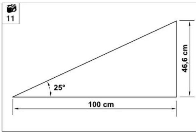
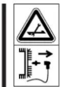
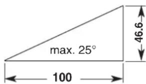
- For safety reasons, the appliance must not be used on slopes with an incline of more than 25° (46.6 %).
Risk of injury!
A slope inclination of 25^ corresponds to a vertical height increase of 46.6 cm for a 100 cm horizontal distance.
In order to ensure an adequate oil supply for the engine, the information in the accompanying engine instruction manual must be additionally observed when using the machine on slopes.
- Warning:
Be particularly careful when moving backwards and when pulling the lawn mower.
Risk of stumbling.
- Be particularly careful when turning the mower around or pulling it towards you.
- Stop the engine or disengage the mowing blade if tilting of the mower is necessary when pushing or driving over surfaces other than grass, and when pushing or driving the mower to and from mowing areas.
- Do not alter the basic setting of the engine.

Never open the grass ejection flap or empty
the grass catcher bag when the mowing blade is running. Rotating blades can cause injury.

- Warning:
Never put hands
or feet on or
underneath
rotating parts. Never touch the rotating blade. Always keep away from the ejection aperture. Always observe the safety distance indicated by the handlebar.
Risk of injury!
- Switch off the engine and remove the spark plug socket from the engine; also remove the ignition key from the appliance (for MB 650 VE):
- Before remedying blockages, including those in the ejection chute.
- If the blade has hit a foreign object. The cutting tool needs to be checked for possible damage.
- Before checking,
cleaning or working on
the mower.
- If the mower begins to vibrate excessively it must be checked immediately.
- Before lifting, or carrying the appliance.
- If you leave the mower unattended.
- Before re-filling the tank.

- Beware of the cutting tool running on for several seconds
before coming to a standstill.
- In order to prevent fire hazards, keep the engine, cooling ribs and exhaust free from grass, leaves or escaping oil (or grease).
Maintenance and repairs

Before performing any work on the appliance always remove the spark
plug socket from the engine;
also remove the ignition key
from the appliance
(for MB 650 VE)
Only carry out maintenance work that is described in this instruction manual.
All other procedures should be carried out by a specialist dealer.
VIKING recommends that you have maintenance operations and repairs performed exclusively by a VIKING specialist dealer.
VIKING specialist dealers regularly attend training courses and are provided with technical information.
Only use high-quality tools, accessories and spare parts. Otherwise, there may be a risk of accidents resulting in personal injury or damage to the appliance.
VIKING recommends the use of original VIKING tools, accessories and spare parts. Their properties are optimally adapted to the appliance and the user's requirements.
VIKING original spare parts can be recognised by means of the VIKING spare parts number, the VIKING lettering and where applicable the VIKING spare parts symbol. The symbol alone may also feature on small parts.
- Ensure that all nuts, pins and bolts are securely tightened, so that the appliance is in a safe operating condition.
- If the cutting tool or the lawn mower hits an obstacle or a foreign object, the engine must be switched off and an inspection must be performed by a specialist.
- The lawn mower must not be operated, in particular, with a damaged or bent crankshaft as well as with a damaged or bent mowing blade and guard plate. Risk of injury through defective parts!
-
Check the grass-catching unit regularly for wear, damage or for loss of functionality.
-
In the interests of safety, replace all worn or damaged parts.
- Replace danger signs and warnings on the appliance which have become illegible. Your VIKING specialist has a stock of replacement stickers.
Charger / Starter battery
Warning: petrol is poisonous and extremely inflammable
- Petrol must only be stored in appropriate containers.
- Keep petrol away from

sparks, naked
flames, pilot lights,
heat sources, and
other ignition
sources.
- Only transport the appliance with an empty fuel tank.
- Re-fill the tank out of doors and do not smoke during re-filling.
- Do not fill fuel tank completely, but fill to approx. 4 cm below the edge of the filler neck so that the fuel has room to expand.
- Re-filling with petrol must be performed before the engine is started. When the engine is running or is hot, the tank cap must not be removed and the tank must not be re-filled with petrol. Petrol may be spilled
Fire hazard!
- If petrol is spilled, the engine must only be started after the petrol-contaminated area has been cleaned. All attempts at starting must be avoided until the petrol fumes have dispersed (wipe dry).
- Screw on caps of fuel tank and canister properly and tightly.
- For safety reasons, fuel line, fuel cock, fuel tank, tank cap and connections must be checked regularly for cracks and leaks and replaced if damaged. (Consult a specialist dealer; VIKING recommends a VIKING specialist dealer).
-
Replace damaged exhaust silencers and guards.
-
Never store the appliance with petrol in the tank inside a building. The resulting petrol fumes could come into contact with naked flames or sparks and could be ignited.
- Allow the engine to cool before storing the appliance in an enclosed space.

- The appliance generates poisonous
exhaust gases when the engine is running. These gases may be odourless and invisible. Never work with engine-powered appliances in a closed or poorly ventilated room. Danger to life through poisoning
- If it is necessary to drain the tank, this must be done out of doors (drive until empty).
Description of symbols


Warning:
Read the instruction manual before initial use.


Risk of injury!
Keep other persons
away from the
danger area.


Risk of injury!
Detach the spark plug socket before performing work on the cutting tool or maintenance and cleaning work.


Risk of injury!
Keep your hands and
feet away from the
blades.
Cutting tool runs on for several seconds after switching off (engine/blade brake).


Warning:
Never reach into the working area of the blade while the engine is running.
Risk of injury!
MB 650 T/
V/ VE/ VM/ VR
MB 655 V/ VM/
VR/ G
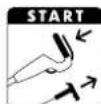
Start the engine
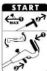
MB 650 VS
MB 655 VS/ GS
MB 655 RS
Set the throttle
lever to the MAX
position, start the
engine, switch on the mowing blade
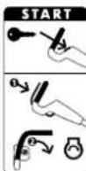
MB 650 VE
Insert the ignition
key,
start the engine

MB 650 T/
V/ VE/ VM/ VR
MB 655 V/ VM/
VR/ G
Stop the engine

MB 650 VS
MB 655 VS/ GS
MB 655 RS
Switch off the
mowing blade
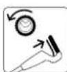
Switch on the wheel drive
Standard equipment

Item Designation Qty.
1 Basic unit 1
2 Handlebar sleeve
3 Flat head bolt 2
4 Rotary handle 2
5 Anti-kink cable protection 2 (MB 650 T 1)
6 Upper part of grass catcher bag 1
7 Lower part of grass catcher bag 1
8 Pin 2
9 Ignition key 1
(MB 650 VE)
10 Charger 1
(MB 650 VE)
• Instruction manual 1
• Instruction manual
Engine 1
NOTE

VIKING supplies chargers with different plugs, depending on the country where sold. The illustrations show a charger with a European plug. Chargers with other plugs are connected to the mains in a similar way.
Preparing the appliance for operation
NOTE

Place the appliance on level and firm ground to perform this work.
Assembling the handlebar

Fit handlebar sleeves: Fit
2= handlebar sleeves onto
A= handlebar as shown.
NOTE

Fit the handlebar sleeves so that the square hole is located on the inner side of the handlebar. The bores in the handlebar and the square hole in the handlebar sleeve must be aligned
Assemble the handlebar: Attach
A= handlebar to both parts of
13= lower handlebar.
Insert
3= flat head bolts through bore from the inside to the outside and tighten securely with
4= rotary knobs.
NOTE

The machined grooves in the threads prevent the rotary handles from becoming completely detached from the bolts (safeguard against loss).
① Installing left anti-kink cable protection:
NOTE

Attach anti-kink cable protection (5) only as shown. Cables must be routed under the handlebar.
Loosen the rotary handle (4) prior to assembly.
Insert all cables in
5= anti-kink cable
protection.
First insert the anti-kink
cable protection into
14= upper bore of
13= lower handlebar. Then engage anti-kink cable protection in
15= lower slot of lower handlebar.
② Installing right anti-kink cable protection:
NOTE

On model MB 650 T, there are no cables on the right-hand side of the handlebar. Only the left anti-kink cable protection (5) must therefore be installed on this lawn mower.
Assembly of the
5= right anti-kink cable protection is performed in the same way as on the left side.
Fold down the handlebar:
CAUTION

Risk of injury!
Before folding the handlebar, the engine must be stopped and the spark plug socket must be removed. The ignition key (9) must also be removed (MB 650 VE) No loads must be placed on the upper handlebar (e.g. work clothing hung over the handlebar).
Danger of pinching!
The handlebar can be folded down by releasing the rotary knobs. For this reason, always hold the upper handlebar (A) with one hand at its highest point when you unscrew the rotary knobs.
Fold down the handlebar for cleaning, for space-saving transport and for storage of the appliance:
Loosen the
4= rotary handles until they move easily backwards and forwards in the machined grooves.
- Fold down the upper handlebar and rest it on the lower housing.
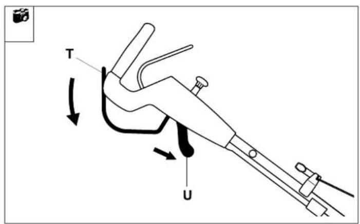
Controls on the handlebar

4
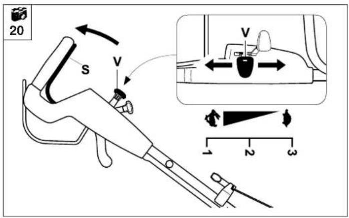
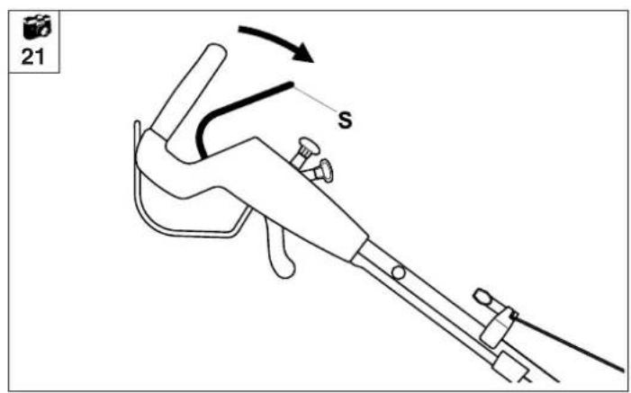
S= Wheel drive lever
All models
T= Motorstop lever
MB 650 T/V,
MB 650 VE/ VM/ VR,
MB 655 V/ VM/ VR/G
T= Blade stop lever
MB 650 VS,
MB 655 VS/ GS/ RS
U= Blade clutch lever
MB 650 VS,
MB 655 VS/ GS/ RS
V= Vario drive lever
MB 650 V/ VE/ VM/ VR,
MB 650 VS,
MB 655 V/ VM/ VR/ VS
MB 655 RS
V= Three-speed drive lever
MB 655 G/ GS
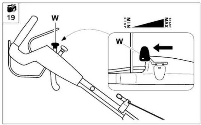
W= Throttle lever
MB 650 VS,
MB 655 VS/ GS/ RS
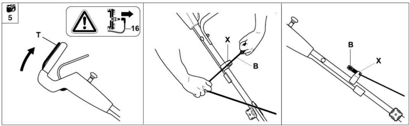
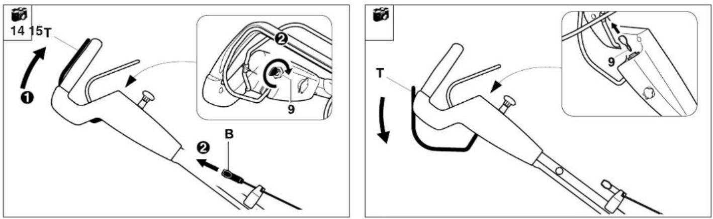
Attaching the starter cable

Disconnect the
16= spark plug socket from the engine.
Press and hold the
T= motorstop lever to release the engine brake. (for MB 650 VS, MB 655 VS/ GS/ RS not required)
Slowly pull out the
B= starter cable and attach to the
X= cable guide as shown in the illustration.
NOTE

The cable guide (X) can be individually adjusted along the handlebar (torx 25 screwdriver not included in standard equipment).
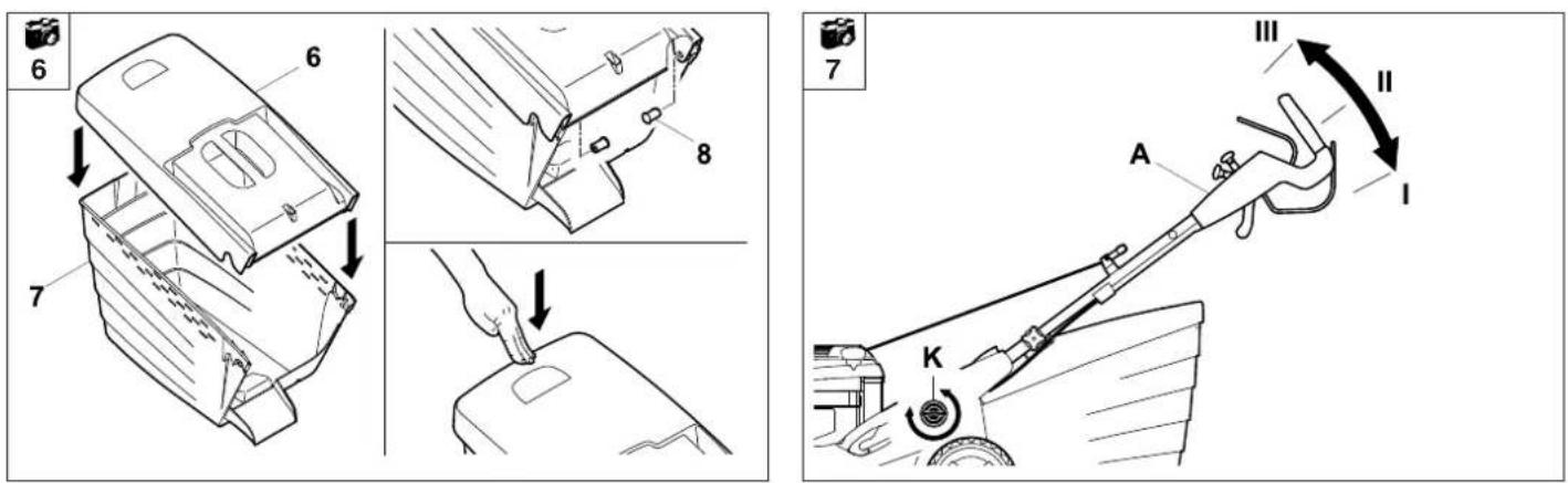
Assembling the grass catcher bag

Fit the
6= upper part of grass
catcher bag onto the
7= lower part of grass catcher bag.
Press the
8= pins through the apertures provided from the inside. Allow the grass catcher bag upper part to engage in the lower part using slight pressure.
Height adjustment of the handlebar

The working height of the handlebar can be set to following positions:
I (low),
II (medium) and III (high):
Loosen the
K= rotary handle for
handlebar height
adjustment by turning
anti-clockwise (approx.
five turns).
Hold the
A= handlebar with both hands and bring to the desired position by moving up or down.
NOTE

Ensure that handlebar adjustment is the same on the left and right sides.
Tighten the
K= rotary handle again by turning clockwise.
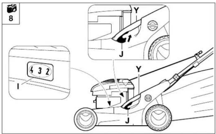
Central cutting height adjustment

CAUTION
Risk of injury!
The engine must be stopped or the mowing blade disengaged prior to adjusting the cutting height.
There are seven cutting height adjustment settings ranging from 30 mm to 85 mm (MB 650 VR, MB 655 VR/ RS: 20 mm to 75 mm).
Level 1 = lowest cutting height
Level 7 = highest cutting height
The
J= adjustment lever for the central height adjustment is located on the left side of the appliance (see illustration).
Hold the appliance at the
Y= handle and pull the
J= adjustment lever upwards and hold, in order to release the detent mechanism.
- Set the required cutting heights by moving the appliance upwards or downwards.
This can be read off the I= cutting height indicator.
Release the
J= adjustment lever again and allow the height adjustment to engage.
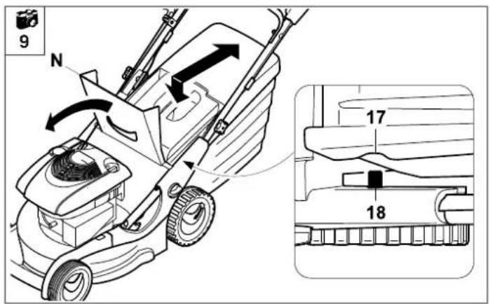
Attaching and detaching the grass catcher bag
CAUTION
Risk of injury!
The engine must be stopped or the mowing blade disengaged prior to attaching and detaching the grass catcher bag.
NOTE
On appliances with mulching equipment, the mulch insert must be removed from the ejection chute before attaching the grass catcher bag (see section "Mulching", for MB 650 VM, MB 655 VM)
Open the
N= ejection flap and hold it
open.


Attaching:
The grass catcher bag is attached by engaging the
17= recesses in the upper part of the catcher bag to the
18= locating pins on the appliance.
- Guide the ejection flap manually downwards onto the grass catcher bag.
Close the
N= ejection flap again manually.
Detaching:
Lift the grass catcher bag upwards, detach from the
18= locating pins and remove.
Close the
N= ejection flap again manually.
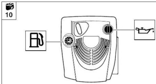
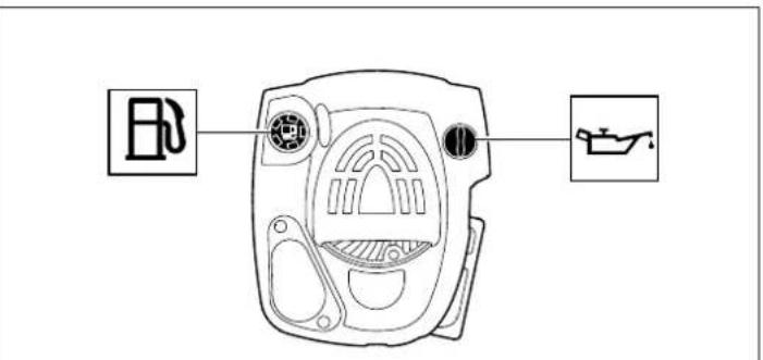
Fuel and engine oil

NOTE

Top up engine oil before initial start (see engine instruction manual).
Engine oil
Please consult the engine instruction manual for the type of engine oil to be used and the filling quantity.
Check engine oil level at regular intervals (see engine instruction manual).
Avoid exceeding or falling below the correct oil level.
Fuel
Recommendation:
Fresh good quality fuel,
normal unleaded petrol (see
engine instruction manual).
Use a funnel when filling the
tank with fuel (not included in
standard equipment).
Notes on mowing and mulching
NOTE

To ensure a perfect, thick lawn, mow regularly and keep the grass short. Do not cut too short in hot, dry conditions as the lawn will dry out or burn in the sun and become unsightly.
The cutting pattern will be better with a sharp blade than with a blunt one. The blade must therefore be sharpened regularly (dealer).
Mowing on slopes

For safety reasons, the appliance must not be used on slopes with an incline of more than 25° (46.6%).
Risk of injury!
A slope inclination of 25^ corresponds to a vertical height increase of 46.6 cm for a 100 cm horizontal distance. In order to ensure an adequate oil supply for the engine, the information in the accompanying engine instruction manual must be additionally observed when using the machine on slopes.
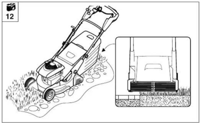
Rear roller mower

12
The MB 650 VR, MB 655 VR, MB 655 RS lawn mowers are equipped with a two-part drive roller on the rear axle.
This permits accurate mowing along lawn edges or around plants.
The grass is also rolled in the direction of travel, creating a characteristic striped lawn pattern.
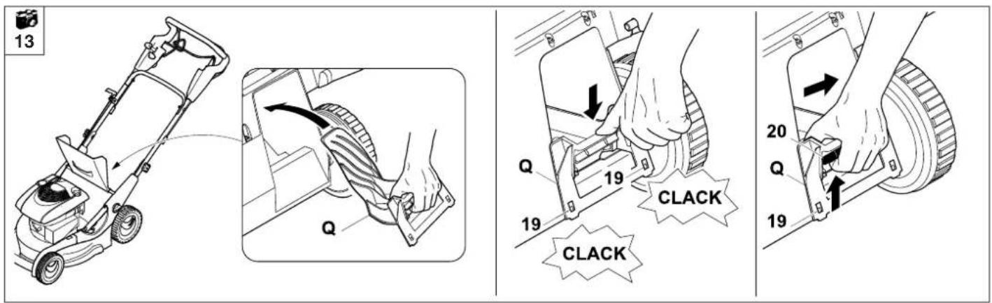
Mulching

13
The MB 650 VM and MB 655 VM multi-mowers are equipped with a special multi-blade and a pre-installed mulch insert.
CAUTION

Risk of injury!
The engine must be stopped before inserting or removing the mulch insert.
Installing the mulch insert
The mulch insert must be inserted in order to use the appliance as a mulching mower:
- Open the ejection flap and hold it open.
Insert the
Q= mulch insert in the ejector chute and press from above until both
19= retaining lugs audibly engage in the housing (see illustration).
- Close the ejection flap.
Working area for operator

35
For safety reasons, the operator must stay within the working area behind the handlebar when starting the engine and when the engine is running. Always observe the safety distance provided by the handlebar.
The lawn mower must only be operated by one person.
Other persons must keep out of the danger area.
The mulch insert must be removed to use the appliance as a rear discharge mower or a grass collector (with attached grass catcher bag).
- Open the ejection flap and hold it open.
Lift the
20= detent catch.
Press the mulch insert downwards and release the
19= retaining lugs from the housing.
Pull the mulch insert diagonally upwards out of the ejection chute.
- Close the ejection flap (rear discharge mower) or attach the grass catcher bag and close the ejection flap (grass collector).
Mulching procedureRemoving
the n
Cutting height four to seven should be selected for mulching, as this is the most suitable height for shredding the grass.
If the cutting height is too low, the mower housing may become clogged, resulting in blockage of the mowing blade.
The lawn cuttings remain on top of the grass instead of being blown to the roots.
It is important to select the correct operating speed and height for mulching to allow the multi-blade to achieve optimal grass shredding and a good cutting pattern.
In high grass it is advisable to work in several stages and in the higher cutting height settings.
Mulching should not be performed when the grass is too high or wet.
Motorstop lever

4
The MB 650 T/ V/ VE/ VM/ VR, MB 655 V/ VM/ VR/ G are equipped with a motorstop device.
The engine with the mowing blade stops immediately when the motorstop device is triggered (release of the
T= motorstop lever) and comes to a complete standstill within 3 seconds.
Measuring the run-on time
Following engine start-up, the blade rotates and a wind noise is audible. The run-on time corresponds to the duration of the wind noise after releasing the motorstop lever. This can be measured using a stopwatch. If the time is exceeded, the machine must not be operated. Consult a specialist dealer; VIKING recommends VIKING specialist dealers.
CAUTION

Risk of injury!
The motorstop device must not be bypassed, e.g. by tying the motorstop lever (T) to the handlebar.
Blade brake clutch (BBC)

4
The MB 650 VS, MB 655 VS/ GS/ RS appliances are equipped with a blade brake clutch:
The mowing blade can be disengaged while the engine is running by operating the
T= blade stop lever and the
U= blade clutch lever (two-handed operation).
Following disengagement (release of the
T= blade stop lever) the mowing blade is disengaged and brought to a standstill within a few seconds (see section "Engaging/Disengaging the mowing blade").
The engine continues to run.
CAUTION

Risk of injury!
Two-handed operation must not be bypassed, e.g. by tying the blade stop lever (T) to the handlebar.
Initial operation of appliance
CAUTION

- Carefully inspect the complete area on which the appliance is to be used and remove any stones, sticks, wires, bones and other foreign objects.
- Start the engine in accordance with the instructions.
- Be particularly careful when turning the mower around or pulling it towards you.
- Risk of injury!
Never put hands or feet on or underneath rotating parts.
- Always wear robust shoes with high-grip soles and long trousers when mowing. Never mow barefoot or, for instance, in sandals.
- Never mow in the vicinity of other persons, particularly children, or animals.
Checking the blade brake clutch
MB 650 VS, MB 655 VS/ GS/ RS:
Before starting work, always perform the following function test three times:
- Start the engine as described in the instruction manual.
- Engage the blade as described in the instruction manual.
A running blade generates a clearly audible wind noise. The running of the blade can be checked by means of the wind noise generated.
- Release the handlebar.
The blade brake clutch disengages the blade from the engine drive, exerting a braking action. The blade comes to a standstill within 3 seconds.
This procedure causes the wind noise to cease. No wind noise is audible when the blade is stopped.
The run-on time corresponds to the duration of the wind noise following disengagement. This can be measured using a stopwatch.
CAUTION

Risk of injury!
If the function test fails (continued audible wind noise despite releasing the handlebar, excessive run-on time), stop the engine, detach the spark plug socket and contact an specialist dealer.
VIKING recommends that you have maintenance operations and repairs performed exclusively by a VIKING specialist dealer.
Starting / stopping the engine - general
Starting and stopping the engine as well as engaging and disengaging the mowing blade is described below. Four model versions must be distinguished:
Version I
MB 650 T/ V/ VE/ VM/ VR, MB 655 V/ VM/ VR/ G
Fixed throttle setting with automatic choke mechanism.
Version II
MB 650 VS, MB 655 VS/ GS/ RS
Adjustable throttle setting with automatic choke mechanism.
Starting the engine – version I
MB 650 T/ V/ VE/ VM/ VR, MB 655 V/ VM/ VR/ G
NOTE
The engine is equipped with a fixed throttle adjustment and always operates at the optimum working speed. Manual adjustment is not necessary.
MB 650 VE is delivered with a charged starter battery.
The starter battery is charged automatically during operation.
Do not start the engine in high grass or when the mower is set to the lowest cutting height, as this makes starting difficult.
Step one:
Press the
T= motorstop lever to the handlebar and hold.


Step two:
MB 650 T/ V/ VM/ VR,
MB 655 V/ VM/ VR/ G
Pull out the
B= starter cable slowly to the point of resistance and then pull vigorously to arm's length.
- Slowly release the cable so that it can gradually be rolled up by the starter.
Repeat as necessary until the engine starts.
MB 650 VE
Insert
9= ignition key into the ignition lock.
Turn
9= ignition key clockwise.
- Do not operate the starter for longer than three to five seconds without interruption. If the engine does not start, release the ignition key and turn it again after approx. ten seconds.
- When the engine starts, release the ignition key. Avoid repeat starting when the engine is running.
NOTE
If the battery is discharged or the starter is defective, the engine can be started using the starter cable (B). Never attempt to start the engine by connecting a charger.
Stopping the engine – version I

MB 650 T/ V/ VE/ VM/ VR,
MB 655 V/ VM/ VR/ G
Switching off the engine
Release the
T= motorstop lever. The engine and blade come to a standstill following a brief run-down time.
MB 650 VE
If the appliance is left unattended, remove
9= ignition key and keep in a safe place.
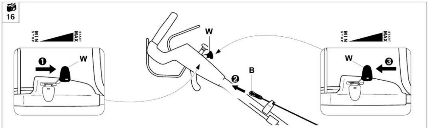
Starting the engine – versions II

MB 650 VS,
MB 655 VS/ GS/ RS
Step one:
Set the
W= throttle lever to the MAX position.
Step two:
Pull out the
B= starter cable slowly to the point of resistance and then pull vigorously to arm's length.
- Slowly release the cable so that it can gradually be rolled up by the starter.
Repeat as necessary until the engine starts.
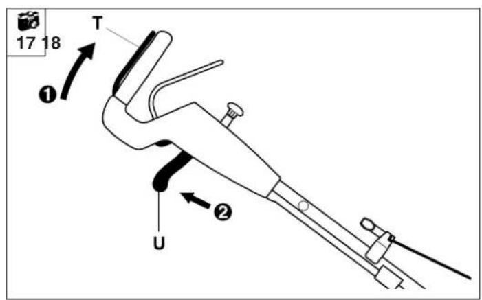
Engaging the mowing blade
MB 650 VS,
MB 655 VS/ GS/ RS
NOTE
Do not engage the mowing blade in high grass and only do so at maximum engine speed.
Step one:
Press the
T= blade stop lever to the handlebar and hold.
Step two:
To engage the mowing blade, pull back the
U= blade clutch lever straight in direction of handlebar to the stop.


NOTE
Pull back blade clutch lever (U) quickly to avoid unnecessary wear in the blade clutch.
The
U= blade clutch lever
engages at the stop (in
the engaged position)
and can be released.
Continue to hold the
T= blade stop lever.
Disengaging the mowing blade

MB 650 VS, MB 655 VS/ GS/ RS
To disengage the mowing blade, release the
T= blade stop lever.
The
U= blade clutch lever moves automatically back to the initial position (disengaged position).
The mowing blade is braked and comes to a stop within a few seconds.
The engine, however, continues to run.
Switching the wheel drive on and off - general
Switching the wheel drive on and off is described below. Three different drive versions must be distinguished, depending on the model version:
MB 650 T
One forward drive speed (single-speed gearbox)
MB 650 V/ VE/ VM/ VR/ VS, MB 655 V/ VM/ VR/ VS/ RS
Continuously variable forward drive speed (vario gearbox)
MB 655 G/ GS
Three selectable forward drive speeds (three-speed gearbox)
Switching on the wheel drive

NOTE

The wheel drive functions only when the engine is running.
The vario drive lever (V) must not be operated when the engine is stopped as this may result in damage to the drive mechanism.
Step one:
All models
Pull the
S= wheel drive lever to the handlebar and hold.
The wheel drive engages.
MB 650 T
Drive speed: 3.5 km/h
Step two:
MB 650 V/ VE/ VM/ VR/ VS,
MB 655 V/ VM/ VR/ VS/ RS
For continuously variable speed increase, pull back the
V= vario drive lever; to reduce the speed, push the lever forwards.
Drive speed:
Continuous, from 2.4 km/h to 4.6 km/h
NOTE
The speed of the vario drive can be freely adjusted during drive operation, without switching the wheel drive off.
Step two:
MB 655 G/ GS
Engage the required gear using the V= three-speed drive lever.
Drive speed:
First gear: 2.3/2,4 km/h
Second gear: 3.2/3,3 km/h
Third gear: 4.1/4,2 km/h
NOTE
The three gears can be freely selected during drive operation, without switching the wheel drive off.
Stopping the engine – versions II

MB 650 VS, MB 655 VS/ GS/ RS
NOTE

Disengage the mowing blade before stopping the engine.
To switch off the engine, move the
W= throttle lever to the STOP position.
Switching off the wheel drive

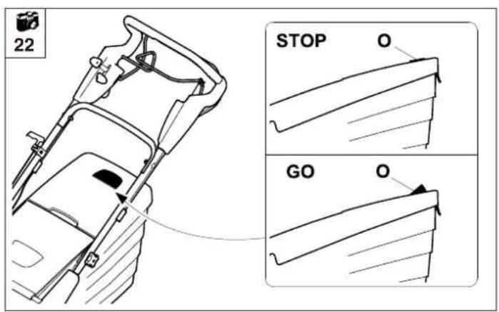
21
To switch off drive operation, release the S= wheel drive lever.
Level indicator

22
The grass catcher bag has a
O= level indicator on the upper part of the catcher bag.
The flow of air that is created by the rotary movement of the mowing blade and is responsible for filling the grass catcher bag raises the level indicator:
The grass catcher bag is filled with cuttings.
When the grass catcher bag is full, this flow of air is reduced and the level indicator sinks onto the on the grass catcher bag upper part: The grass catcher bag is full and must be emptied (see section "Emptying the grass catcher bag").
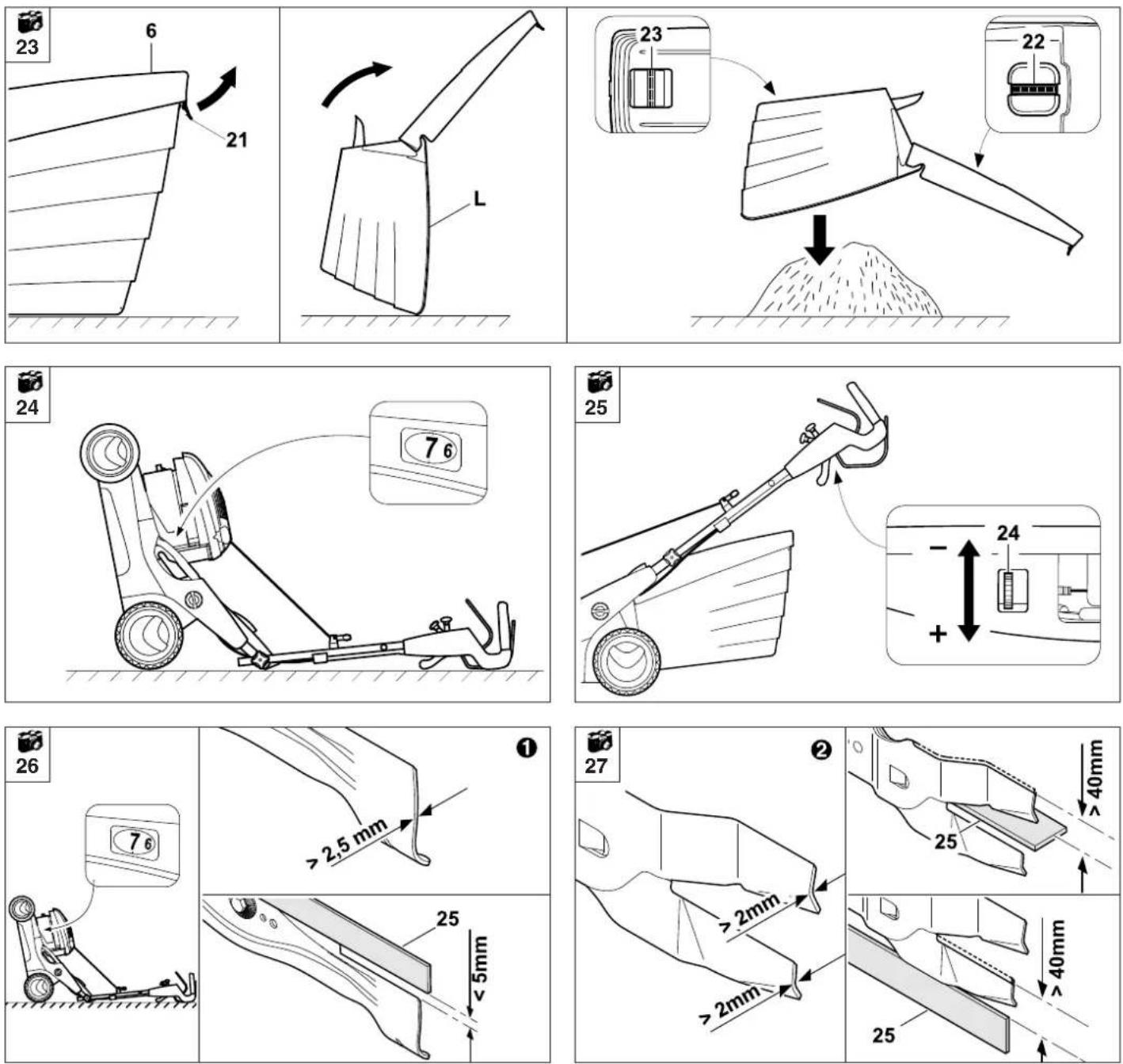
Emptying the grass catcher bag

23
CAUTION

Risk of injury!
The engine must always be switched off or the mowing blade disengaged and stopped prior to emptying the grass catcher bag.
NOTE

A completely filled grass catcher bag can weigh up to 20 kg.
- Detach the grass catcher bag from the appliance (see section "Attaching and detaching the grass catcher bag").
Open the grass catcher bag at the
21= tab and open the
6= upper part of the grass catcher bag upwards.
Fold back the full
L= grass catcher bag.
The grass catcher bag can be held securely and emptied easily using the
22= handle (upper part of grass catcher bag) and the
23= handle (lower part of grass catcher bag).
Maintenance
CAUTION


Risk of injury!
In order to prevent inadvertent starting of the engine, prior
to any maintenance and cleaning work, prior to transport and prior to storing, always remove the spark plug socket from the engine; also remove the ignition key from the appliance (MB 650 VE)

Risk of injury! Always wear gloves.
Do not touch the mowing blade until it be to a standstill.
Always allow the engine to cool before carrying out maintenance and cleaning work.
If you do not have the necessary expertise or auxiliary equipment, please always contact a specialist dealer.
VIKING recommends that you have maintenance operations and repairs performed exclusively by a VIKING specialist dealer.
VIKING recommends the use of original VIKING tools, accessories and spare parts.
Cleaning the appliance

23
Maintenance interval: Each time the appliance is used
Clean the appliance thoroughly after mowing. Looking after your appliance carefully will protect it against damage and extend its service life.
Clean the underside of the mower with water and a brush. Detach accumulated cutting deposits in the housing and in the ejection chute beforehand using a stick.
Clean the mowing blade.
Never spray water on engine components, seals or bearing points. This may result in damage and expensive repairs.
Do not use aggressive cleaning agents. These cleaners can damage plastics and metals, impairing safe operation of your VIKING mower.
If you are unable to remove the dirt with water, using a brush or a cloth, VIKING recommends the use of a special cleaner (e.g. STIHL special cleaner).
CAUTION

Risk of injury!
Before tilting upwards, place the mower on firm, horizontal and level ground and adjust it to the highest cutting level (level 7), otherwise the mower might tilt forwards again.
NOTE

Lilt the front of the mower upwards when carrying out cleaning or maintenance work. Before tilting upwards, empty the fuel tank, detach the grass catcher bag, fold down the upper handlebar (see section "Assembling the handlebar") and lift the ejection flap.
Wheels and gearbox
The ball bearings of the wheels are maintenance-free.
The vario gearbox and the three-speed gearbox are maintenance-free.
Adjusting the wheel drive cable

Maintenance interval:
As required (wheel drive does not engage when the wheel drive lever is actuated)
The tension of the cable is adjusted correctly at the factory. However, the cable may have to be adjusted again following an extended period of use.
The adjustment is made using an
24= adjustment screw located on the upper handlebar.
CAUTION

Risk of injury!
If the wheel drive cable is incorrectly adjusted, the mower may start to move unintentionally immediately when started and this may result in injury or damage to the appliance.
Correct adjustment:
The driving wheels must lock after approx. one third of the lever travel.
Actuate the drive lever while pulling the lawn mower backwards.
The cable tension is increased by turning the
24= adjustment screw in the "+" direction, turning it in the "-" direction reduces the tension.
CAUTION

Risk of injury!
If, when pulling back, the driving wheels are locked when the drive lever is not actuated, the cable is adjusted incorrectly and the mower drive is permanently activated.
The adjustment must be repeated (if necessary, contact a specialist dealer; VIKING recommends VIKING specialist dealers).
Mowing blade maintenance

CAUTION
Risk of injury!
If you do not have the necessary expertise or auxiliary equipment, please always contact a specialist dealer. (VIKING recommends VIKING specialist dealers).
VIKING recommends the use of original VIKING tools, accessories and spare parts.
Maintenance interval: Before each use
Tilt the mower upwards into the cleaning position.
- Clean the mowing blades and all fastening elements (retaining washer, blade fastening screws, guard plate), check for damage (notches, cracks or deformation) and wear and replace if necessary.
Wear limits:
① Standard blade:
The blade thickness must be at least 2.5 mm at any point. (Check using slide calliper).
The blades may not be ground back by more than
5 mm during sharpening.
When inspecting, place a
25= ruler against the front blade edge and check for wear.
② Multi-blade (MB 650 VM, MB 655 VM):
The blade thickness must be at least 2 mm at any point. (Check using slide calliper).
The blades may not be ground back to a width of under 40 mm during sharpening.
When inspecting, place a
25= ruler against the rear blade edge and check for wear on the lower and upper blades.
CAUTION

Risk of injury!
A worn blade may break off and cause serious injuries. The instructions for blade maintenance must therefore always be observed.
Blades are subjected to differing degrees of wear depending on the location and duration of use. If you use the mower on sandy ground or use it frequently under dry conditions, the blade will be subjected to greater loads and will wear more quickly than the average.
Always replace the blade fastening screw(s) (26), retaining washer (27) and guard plate (28) when replacing the mowing blade.
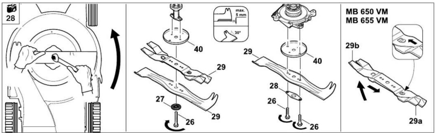
Removing the mowing blades

Risk of injury! Always wear gloves.
Loosen the
26= blade fastening screw(s) using an A/F 17 spanner and remove together with the
27= retaining washer or
28= guard plate.
Remove
29= mowing blade together with
40= thrust washer.
MB 650 VM, MB 655 VM:
The
29= mowing blade consists of an upper blade (29a) and a lower blade (29b). It can be separated for convenient regrinding.

28
Push the upper blade (29a) to the left as far as the stop and then lift the opposite side.
The upper blade (29a) is then disengaged from the lower blade (29b) by pushing to the right.
Sharpening the mowing blade
If mowing results deteriorate with time, the mowing blade is probably blunt.
The following points must be observed when re-sharpening the mowing blade:
- Cool the mowing blade when sharpening, e.g. with water. The blade must not be allowed to display blue colouring, as this would reduce its cutting quality.
- Sharpen blades evenly to prevent vibration due to imbalance.
CAUTION

Risk of injury!
Check blade for damage before installing.
The blade must be replaced if notches or cracks are identified, if the blades are worn back by 5 mm, or if the blade is thinner than 2.5 mm (Standard blade) / 2 mm (Multi-blade) at any point.
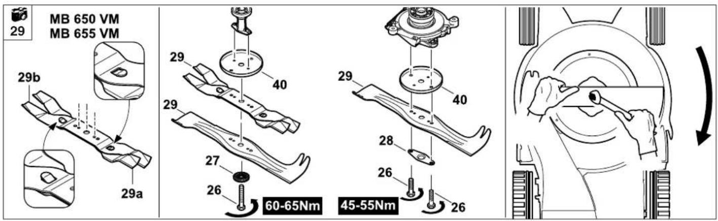
Installing the mowing blade

29

Risk of injury!
Always wear
gloves.
MB 650 VM, MB 655 VM:
Engage the upper blade (29a) in the lower blade (29b) as illustrated. For this purpose, ensure that the bores in both blades are aligned.
Install
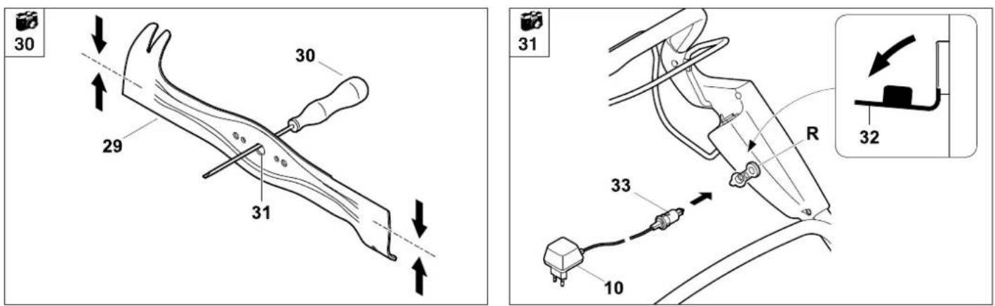
Checking balance of mowing blade

Assemble the multi-blade before checking (see section "Installing the mowing blade"). Guide
30= screwdriver through
31= central bore of
29= mowing blade and align the mowing blade horizontally.
If the mowing blade is properly balanced it will remain in this horizontal position.
40= thrust washer and
29= mowing blade with the curved edges/vanes pointing upwards.
Tighten the
26= blade fastening screw(s) with the
27= retaining washer or
38= guard plate to a torque of 60 - 65 Nm
(MB 650 VS, MB 655 VS/ GS/ RS: 45 - 55 Nm).
CAUTION

Risk of injury!
Observe the specified torque of 60 - 65 Nm (MB 650 VS, MB 655 VS/ GS/ RS: 45 - 55 Nm) when tightening the blade fastening screws, as the secure attachment of the cutting tool depends on this.
MB 650 T/ V/ VE/ VR/ VM, MB 655 V/ VR/ G/ VM:
Replace retaining washer (27) each time the blade is installed.
Additionally secure the blade fastening screw (26) with Loctite 243.
Starter battery

31
The starter battery is maintenance-free and is charged automatically during operation. If discharging occurs (engine starting problems), the starter battery must be recharged.
NOTE

Always charge the starter battery in an enclosed, well-ventilated room which is dry and weather-protected (splash water).
Charging starter battery:
Only use the original battery charger supplied (10).
Open
32= flap of the charging socket. Connect
33= charger plug to
R= charging socket.
- Then connect charger to the plug socket.
The charging time is approx. 24 hours.
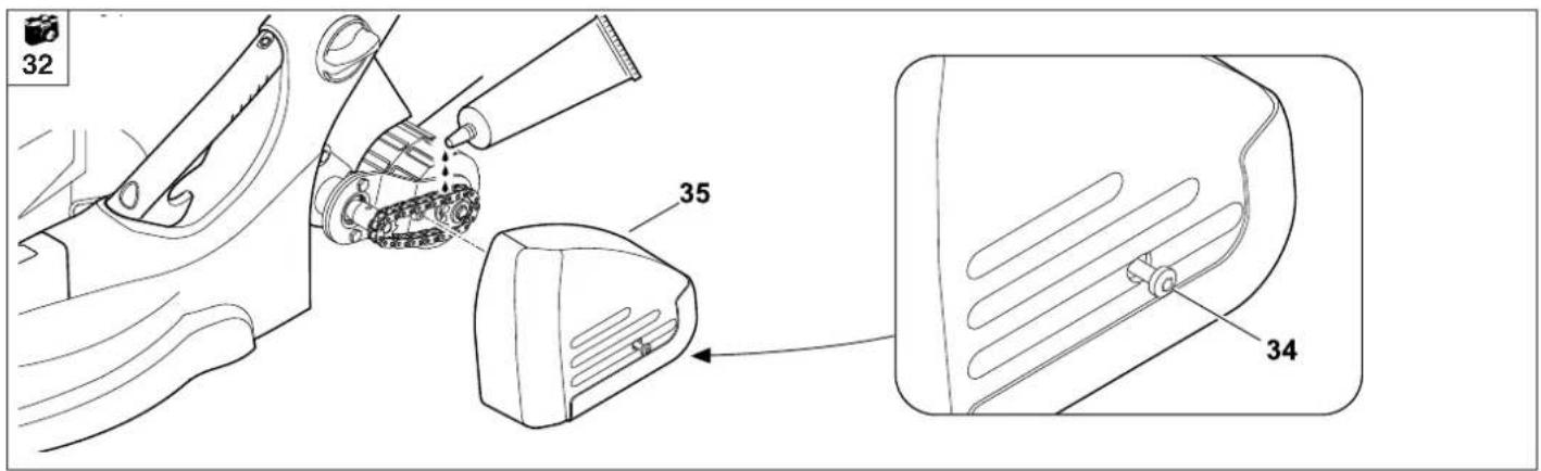
Rear roller maintenance (MB 650 VR.
MB 655 VR/RS)

32
The ball bearings of the rollers are maintenance-free.
The Vario gearbox is maintenance-free.
Lubricate the drive chain at least once a year or as necessary using commercially available grease.
For servicing purposes, remove
34= bolt (Torx 25) and remove
35= cover.
Blade brake clutch maintenance
The blade brake clutch is subject to natural wear. In order to fulfil its function, regular maintenance and servicing work must be performed on the blade brake clutch by trained personnel (VIKING recommends that you have maintenance operations and repairs performed exclusively by a VIKING specialist dealer) in the following intervals:
Professional use: every six months
(commercial use of the mower)
Private use: annually
Combustion engine
Maintenance interval: See engine instruction manual
Observe the operating and maintenance instructions contained in the attached engine instruction manual. To achieve a long service life, it is always particularly important to maintain a sufficient level of oil and to change the oil and air filter regularly.
The recommended oil change intervals as well as information on engine oil and filling quantities can also be found in the engine instruction manual.
The cooling ribs must always be kept clean to ensure that the engine is adequately cooled.
Storage
The storage room should be dry and free of dust. The mower should also be stored out of reach of children.
Any appliance faults must be remedied prior to storage in order to maintain a safe operating condition.
Empty fuel tank and carburettor (e.g. by running empty).
Stationary period (winter break)
Note the following points when storing the mower for long periods:
- Carefully clean all external parts of the engine and appliance, in particular the cooling ribs.
- Thoroughly lubricate/ grease all moving parts.
- Empty fuel tank and carburettor (e.g. by running empty).
- Unscrew spark plug and pour approx. 3 cm ^4 of engine oil into the engine via the spark plug hole. Turn the engine several times with the spark plug removed.
CAUTION
Keep the spark plug socket away from the spark plug hole due to danger of ignition.

Re-install the spark plug.
- Perform oil change (also see engine instruction manual).
- Cover the engine well and store the appliance in a dry, dust-free room in the normal position.
MB 650 VE
- Charge battery fully.
Store the appliance with battery in a dry place at a temperature not below +5 °C, as temperatures lower than this will destroy the battery.
Charge the battery at least once during the winter break (at the latest after 6 months).
Charge the battery fully for approx. 24 hours before the start of the season.
Standard spare parts
Mowing blade:
MB 650 T/ V/ VE/ VR/ VS
6360 760 9992
MB 650 VM
6105 760 9900
MB 655 V/ VR/ G/ VS/ GS/ RS
6375 760 9991
MB 655 VM
6107 760 9900
NOTE

The fastening elements of the mowing blade (e.g. blade fastening screw, lock washer) must be replaced when replacing the blade or when installing the blade. Spare parts are available from a VIKING specialist dealer.
Transport

Always wear
gloves in order
to prevent

injuries due to sharp-edged and hot components.
- Switch off the mower prior to transport, disconnect spark plug socket and allow the blade to come to a stop.
- Only transport the appliance once the engine has cooled down and the fuel tank is empty.
- The mower must always be carried by two persons.
- Use suitable loading aids (loading ramps, lifters).
- Secure the appliance on the load floor using adequately-dimensioned fastening material (belts, ropes etc.).
- When transporting the machine, always observe regional legislation, especially regarding load security and the transport of objects on load floors.
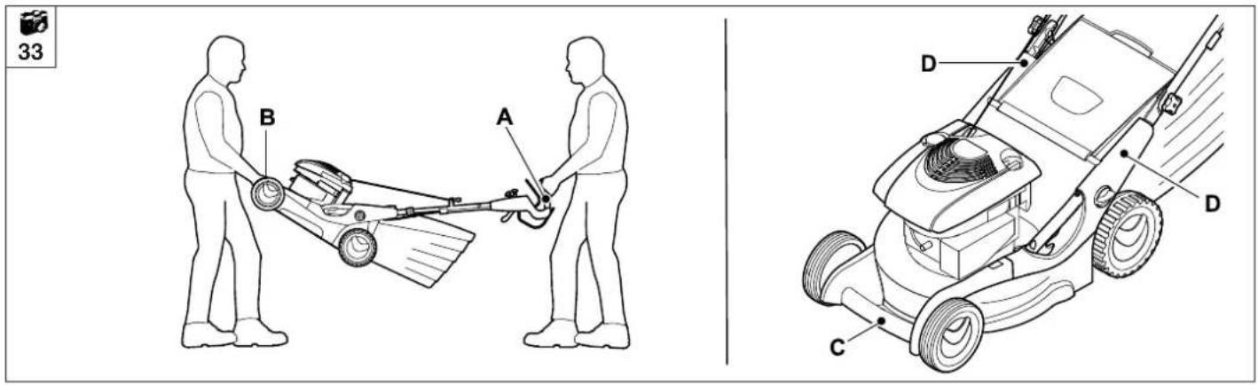
Lifting points for lifting or carrying the machine:
Handles (A)
Carrying handle (B)
Lashing points:
Carrying handle (C)
Lower handlebar (D)
Environmental protection
Lawn cuttings should be composted and not disposed of in household waste.
The appliance, its
packaging and accessories are all produced from recyclable materials and must be disposed of accordingly.
By disposing of materials separately, and in an environmentally-friendly manner, valuable resources can be re-used.
Scrapping the lawn mower:
Following the end of the useful service life of the appliance, it should be disposed of for recycling.
Render the machine unusable prior to disposal. For this purpose, remove ignition cable(s), ignition key and battery (see section „Removing and disposing of battery”), empty the fuel tank and drain the engine oil in particular.
Ensure that before scrapping an old lawn mower, the battery (MB 650 VE), engine oil and petrol are properly disposed of.
Observe regional regulations.
Risk of injury caused by the mowing blade.
Always store an old mower in a safe place prior to scrapping. Ensure that the appliance and the blades are kept out of reach for children.
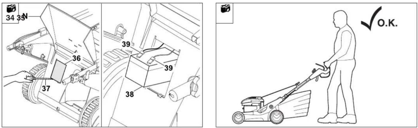
Removing and
disposing of battery
(MB 650 VE)

CAUTION
Risk of injury!

Always detach spark plug socket from engine prior to removal of the
battery, also remove the ignition key from the appliance.
Keep battery contacts away from metal parts in order to prevent spark formation.
NOTE

Do not dispose of the battery with domestic waste, but hand in to a specialist dealer
or at a hazardous waste collection point.
Open
N= ejection flap and hold it
open.
Remove
36= cover of battery compartment using a
37= screwdriver.
Pull out
38= battery and disconnect
39= cable. Remove the battery.
- Dispose of the battery properly and reinstall the battery compartment cover.
Troubleshooting
| Fault | Possible cause | Remedy Page Illustration | | |
| - Engine will not start - Motorstop lever is not pulled;- Throttle lever is in STOP position- Throttle cable disengaged or damaged (e.g. kinked)- No fuel in tank; fuel line blocked- Inferior, dirty or old fuel in tank | - Press motorstop lever to handlebar;- Set throttle lever to the MAX position (for MB 650 VS, MB 655 VS/ GS/ RS)- Attach or replace throttle cable (for MB 650 VS, MB 655 VS/ GS/ RS)- Top up fuel; clean fuel line- Always use fresh, good quality fuel, normal lead-free petrol, clean the fuel tank, fuel line and carburettor | 12; 141410; 10; 10 | 14; 17161010 | |
see engine instruction manual
If necessary, contact a specialist dealer; VIKING recommends VIKING specialist dealers.
| Fault | Possible cause | Remedy Page Illustration | | |
| - Engine will not start (continued) | - Dirty air filter- Spark plug socket disconnected from spark plug; ignition lead incorrectly fastened to socket- Spark plug dirty or damaged; incorrect electrode gap- Engine is flooded due to several starting attempts- Mower housing is blocked | - Clean/replace air filter- Connect spark plug socket; check connection between ignition lead and connector- Clean or replace spark plug; Adjust electrode gap- Unscrew spark plug and dry; Set throttle lever to the STOP position, pull the starter cable several times with the spark plug removed (for MB 650 VS, MB 655 VS/ GS/ RS)- Clean mower housing; disconnect spark plug socket before cleaning; also remove the ignition key from the appliance (MB 650 VE) | ☐; ☒ | 19 |
| ☐; ☒ |
| ☐; ☒ |
| ☐; ☒ |
| 15 |
| 16 | 24 |
| 14 | 15 |
see engine instruction manual
If necessary, contact a specialist dealer; VIKING recommends VIKING specialist dealers.
| Fault | Possible cause | Remedy Page Illustration | | |
| - Starting problems or deteriorating engine performance | - Water in fuel tank and carburettor; carburettor blocked- Dirty fuel tank- Dirty air filter- Dirty spark plug- Mowing grass which is too long or too wet | - Empty fuel tank, clean fuel tank, fuel line and carburettor- Clean fuel tank- Clean air filter- Clean spark plug- Work at appropriate cutting height and mowing speed for mowing conditions | ☐; ☒☐; ☒☐; ☒9 | 8 |
| - No response when wheel drive lever is actuated | - Wheel drive cable incorrectly adjusted- V-belt worn- Wheel drive cable damaged (e.g. kinked) | - Re-adjust wheel drive cable- Replace V-belt- Replace wheel drive cable | 17☒☒ | 25 |
| - Vario drive speed control not functioning | - Lever moved in wrong direction- Vario drive cable disengaged or damaged | - Tighten blade fastening screw(s)- Attach or replace vario drive cable | 15☒ | 20 |
| - Engine overheating - Dirty cooling | - Oil level in engine too low | - Clean cooling ribs- Top up engine oil | 20; ☐10; ☐ | 10 |
see engine instruction manual
If necessary, contact a specialist dealer; VIKING recommends VIKING specialist dealers.
| Fault | Possible cause | Remedy Page Illustration | | |
| - Poor cut, lawn turning yellow - Mowing blade is blunt or worn- The rate of feed is too high in relation to the cutting height- Engine speed too low | - Re-sharpen or replace mowing blade- Reduce the rate of feed and/or select correct cutting height (do not work at lowest cutting height = Level 1)- Set throttle lever to the MAX position(for MB 650 VS,MB 655 VS/ GS/ RS) | 17; ✘15; 914 | 20; 816 | |
| - Ejection chute blocked - Mowing blade is worn- Mowing grass which is too long or too wet- Engine speed too low | - Replace the mowing blade- Work at appropriate cutting height and mowing speed for mowing conditions (not at the lowest cutting height = level 1)- Set throttle lever to the MAX position(for MB 650 VS,MB 655 VS/ GS/ RS) | 17; ✘15; 914 | 20; 816 | |
| - Excessive vibration during operation | - Blade fastening screw(s) are loose- Engine mounting is loose- Blade imbalance due to incorrect re-sharpening or fracture- Anti-vibration elements worn | - Tighten blade fastening screw(s)- Tighten engine fastening bolts- Re-sharpen (balance) or replace blade- Replace anti-vibration elements | 17; ✘17; ✘ | |
see engine instruction manual
If necessary, contact a specialist dealer; VIKING recommends VIKING specialist dealers.
Technical specifications
| Model | Unit | MB 650.0 T | MB 650.1 V ^1 MB 650.1 VM ^2 MB 650.0 VE ^3 MB 650.0 VR ^4 | MB 650.0 VS |
| Serial number | | 6360 | 6360 | 6360 |
| Engine, design | | 4-stroke combustion engine |
| Type | | B&S | B&S | B&S |
| Series 675 | Series 750 ^1,2 Series 675 ^3,4 | Series 675 |
| Displacement | ccm | 190 | 161 ^1,2 /190 ^3,4 | 190 |
| Nominal output at nominal speed | kW - rpm | 2.5 - 2800 | 2.5 - 2800 | 2.5 - 2800 |
| Fuel tank | l | 0.9 | 1.0 ^1,2 /0.9 ^3,4 | 0.9 |
| Battery type (MB 650.0 VE) | | - | Lead / gel12V 3Ah | - |
| Starter | | Cable start | Cable start ^1,2,4 /Electric start ^8 | Cable start |
| Cutting utilities | | Cutter bar | Cutter bar | Cutter bar |
| Cutting width | cm | 48 | 48 | 48 |
| Speed Cutter bars | rpm | 2800 | 2800 | 2800 |
| Drive Cutter bars: | | permanent | permanent | BBC |
| In accordance with Guideline 2000/14/EC: |
| Guaranteed |
| Acoustic power level L _WAd | dB(A) | 96 | 96 | 96 |
| In accordance with Guideline 2006/42/EC: |
| Sound pressure level at |
| workplace L _pA | dB(A) | 83 | 83/83/83/84 | 83 |
| Uncertainty K _pA | dB(A) | 2 | 2/2/2/2 | 2 |
| Specified vibration characteristicin accordance with EN 12096: |
| measured value a _hw | m/sec ^2 | 5.50 | 3.50 ^1,2 /5.34 ^3 /6.01 ^4 | 5.75 |
| Uncertainty K _hw | m/sec ^2 | 2.20 | 1.75 ^1,2 /2.14 ^3 /2.40 ^4 | 2.30 |
| Measurement in accordance with EN 20 643 |
| Tightening torque |
| Blade fastening screw(s) | Nm | 60 - 65 | 60 - 65 | 45 - 55 |
| Wheel drive, rear wheel | | 1-speed | Vario | Vario |
| Wheel diameter (front) | mm | 200 | 200/200/200/180 | 200 |
| Wheel diameter (rear) | mm | 230 | 230/90 (Roller) | 230 |
| Cutting heights | mm | 30 - 85 | 30 - 85 | 30 - 855 |
| Cutting heights MB 650.0 VR | mm | | 20 - 75 | |
| Grass catcher bag capacity | l | 75 | 75 | 75 |
| Weight | kg | 42 | 42/42/46/43 | 47 |
| LxWxH | cm | 168x52x115 | 168x52x115 | 168x52x115 |
| Model | Unit | MB 655.1 VMB 655.1 VMMB 655.1 VR | MB 655.1 G | MB 655.1 GSMB 655.1 VSMB 655.2 RS |
| Serial number | | 6375 | 6375 | 6375 |
| Engine, design | | | 4-stroke combustion engine | |
| Type | | B&S | B&S | B&S |
| | Series 750 | Series 750 | Series 750 |
| Displacement | ccm | 161 | 161 | 161 |
| Nominal output at nominal speed | kW - rpm | 2.5 - 2800 | 2.5 - 2800 | 2.5 - 2800 |
| Fuel tank | l | 1.0 | 1.0 | 1.0 |
| Starter | | Cable start | Cable start | Cable start |
| Cutting utilities | | Cutter bar | Cutter bar | Cutter bar |
| Cutting width | cm | 53 | 53 | 53 |
| Speed Cutter bars | rpm | 2800 | 2800 | 2800 |
| Drive Cutter bars: | | permanent | permanent | BBC |
| In accordance with Guideline 2000/14/EC: |
| Guaranteed |
| Acoustic power level L_WAd | dB(A) | 98 | 98 | 98 |
| In accordance with Guideline 2006/42/EC: |
| Sound pressure level at workplace L_pA | dB(A) | 84 | 84 | 85 |
| Uncertainty K_pA | dB(A) | 2 | 2 | 2 |
| Specified vibration characteristic in accordance with EN 12096: |
| measured value a_hw | m/sec ^2 | 3.80/3.80/3.80 | 3.80 | 3.80 / 3,50 (RS) |
| Uncertainty K_hw | m/sec ^2 | 1.90/1.90/1.90 | 1.90 | 1.90 / 1,75 (RS) |
| Measurement in accordance with EN 20 643 |
| Tightening torque |
| Blade fastening screw(s) | Nm | 60 - 65 | 60 - 65 | 45 - 55 |
| Wheel drive, rear wheel | | Vario | 3-speed | 3-speed / Vario / Vario |
| Wheel diameter (front) | mm | 200/200/180 | 200 | 200/200/180 |
| Wheel diameter (rear) | mm | 230/90 (Roller) | 230 | 230/90 (Roller) |
| Cutting heights | mm | 30 - 85 | 30 - 85 | 30 - 85 |
| Cutting heights MB 655.1 VR/MB 655.2 RS | mm | 20 - 75 | | 20 - 75 |
| Grass catcher bag capacity | l | 75 | 75 | 75 |
| Weight | kg | 45/46/45 | 46 | 50/49/49 |
| LxWxH | cm | 169x57x115 | 169x57x115 | 169x57x115 |
We,
VIKING GmbH
declare, that the machine,
manually-operated lawn
mower with combustion
engine,
Manufacturer's
brand: VIKING
Serial number: 6360
Type: MB 650.0 T
MB 650.1 V
MB 650.0 VE
MB 650.1 VM
MB 650.0 VR
MB 650.0 VS
Serial number: 6375
Type: MB 655.1 V
MB 655.1 VM
MB 655.1 VR
MB 655.1 VS
MB 655.1 G
MB 655.1 GS
MB 655.2 RS
conforms to the following EC guidelines:
97/68/EC, 2000/14/EC,
2014/30/EU, 2006/42/EC,
2006/66/EC (MB 650.0 VE)
The product has been developed and manufactured in conformance with the following standards:
EN ISO 5395-1
EN ISO 5395-2
Applicable conformity assessment procedure:
Appendix VIII (2000/14/EC)
Name and address of relevant, named location:
TÜV Rheinland LGA Products GmbH
Tillystraße 2
D-90431 Nuernberg
Compilation and storage of technical documentation:
Sven Zimmermann
VIKING GmbH
Measured sound power level:
94.1 dB(A) MB 650.0 T
94.8 dB(A) MB 650.1 V
94.5 dB(A) MB 650.0 VE
94.8 dB(A) MB 650.1 VM
95.4 dB(A) MB 650.0 VR
94.1 dB(A) MB 650.0 VS
96.0 dB(A) MB 655.1 V
96.0 dB(A) MB 655.1 VM
96.3 dB(A) MB 655.1 VR
96.0 dB(A) MB 655.1 VS
96.0 dB(A) MB 655.1 G
96.3 dB(A) MB 655.1 GS
97.0 dB(A) MB 655.2 RS
Guaranteed sound power level:
96 dB(A) MB 650.0 T
MB 650.1 V
MB 650.0 VE
MB 650.1 VM
MB 650.0 VR
MB 650.0 VS
98 dB(A) MB 655.1 V
MB 655.1 VM
MB 655.1 VR
MB 655.1 G
MB 655.1 VS
MB 655.1 GS
MB 655.2 RS
The year of manufacture and serial number appear on the identification plate of the machine.
Langkampfen,
02.01.2016
VIKING GmbH

Sven Zimmermann
Head of Design
This instruction manual is protected by copyright. All rights reserved, especially the right of reproduction, translation and processing using electronic systems.
Minimising wear and preventing damage
Important information on maintenance and care of the product group
Petrol lawn mowers
Please always observe the following important information for the prevention of damage or excessive wear to your VIKING appliance:
1. Wearing parts
Some parts of the VIKING appliance are subject to normal wear even when used properly and must be replaced in due time depending on type and duration of use.
These include:
- Blade
- Grass catcher bag
- Toothed belt
- Protection bumpers
- Battery
(MB 650 VE)
- Brake band
(for MB 650 VS,
MB 655 VS/ GS/ RS)
- Drive chain
(MB 650 VR,
MB 655 VR/ RS)
The VIKING appliance must be used, maintained and stored with the care described in this instruction manual.
Please refer to the engine manufacturer's operating instructions for information on petrol and engine oil.
Any damage caused by non-observance of the safety, operating and maintenance instructions is the sole responsibility of the user.
This applies in particular to:
- improper use of the product
- product modifications not approved by VIKING
-
The use of tools or accessories which are not approved or suitable for the appliance, or are of inferior quality.
-
use of the product for sporting or competitive events
- resultant damage due to continued use of the product with defective components
3. Maintenance operations
All work listed in the section "Maintenance" must be performed regularly. If these maintenance operations cannot be carried out by the user himself, a specialist dealer must be commissioned to do it.
VIKING recommends that you have maintenance operations and repairs performed exclusively by a VIKING specialist dealer.
VIKING specialist dealers regularly attend training courses and are provided with technical information.
If these operations are neglected, faults may arise which are the responsibility of the user.
These include:
- corrosive and other resultant damage caused by incorrect storage
- Damage to the appliance through the use of inferior-quality spare parts.
- Damage due to untimely or inadequate maintenance or damage due to maintenance or repair work not performed in the workshops of specialist dealers.
Service schedule
Please give this instruction manual to your VIKING specialist dealer when you have maintenance work performed on your VIKING product.
Your VIKING specialist will confirm the correct performance of the required service operations in the "Service schedule" section.
Model: MB
Serial number:

Handed over
Date: ____ ____ ____ ____ ____

Next service
Date: ____ ____ ____ ____ ____
Date: ____ ____ ____ ____ ____

Next service
Date: ____ ____ ____ ____
Date: ____ ____ ____ ____ ____

Next service
Date: ____ ____ ____ ____ ____
Date: ____ ____ ____ ____ ____

Next service
Date: ____ ____ ____ ____
Date: ____ ____ ____ ____ ____

Next service
Date: ____ ____ ____ ____ ____
Date: ____ ____ ____ ____ ____

Next service
Date: ____ ____ ____ ____ ____
Date: ____ ____ ____ ____ ____

Next service
Date: ____ ____ ____ ____ ____
Chère cliente, cher client,
97/68/EC, 2000/14/EC,
2014/30/EU, 2006/42/EC,
2006/66/EC (MB 650.0 VE)
96,0 dB(A) MB 655.1 V
96,0 dB(A) MB 655.1 VM
96,3 dB(A) MB 655.1 VR
96,0 dB(A) MB 655.1 VS
96,0 dB(A) MB 655.1 G
96,3 dB(A) MB 655.1 GS
97,0 dB(A) MB 655.2 RS
Stilleggen (winterpauze) 20
MB 650 VS
MB 655 VS/ GS
MB 655 RS
Hendel
gasinstelling in
stand MAX,
MB 650 VE
Contactsleutel
insteken,
motor starten

Motor uitschakelen
MB 650 T/ V/
VE/ VM/ VR
MB 655 V/ VM/
VR/ G

MB 650 VS
MB 655 VS/ GS
MB 655 RS
Maaimessen
uitschakelen
Stilleggen (winterpauze)
97/68/EC, 2000/14/EC,
2014/30/EU, 2006/42/EC,
2006/66/EC (MB 650.0 VE)
Het product is in
TÜV Rheinland LGA Products
GmbH
Tillystraße 2
D-90431 Nürnberg
Samenstelling en klassement
van de Technische
Documentatie:
Sven Zimmermann
VIKING GmbH
96,0 dB(A) MB 655.1 V
96,0 dB(A) MB 655.1 VM
96,3 dB(A) MB 655.1 VR
96,0 dB(A) MB 655.1 VS
96,0 dB(A) MB 655.1 G
96,3 dB(A) MB 655.1 GS
97,0 dB(A) MB 655.2 RS
97/68/EC, 2000/14/EC,
2014/30/EU, 2006/42/EC,
2006/66/EC (MB 650.0 VE)
96,0 dB(A) MB 655.1 V
96,0 dB(A) MB 655.1 VM
96,3 dB(A) MB 655.1 VR
96,0 dB(A) MB 655.1 VS
96,0 dB(A) MB 655.1 G
96,3 dB(A) MB 655.1 GS
97,0 dB(A) MB 655.2 RS
97/68/EC, 2000/14/EC,
2014/30/EU, 2006/42/EC,
2006/66/EC (MB 650.0 VE)
El producto ha sido
TÜV Rheinland LGA Products
GmbH
Tillystraße 2
D-90431 Nürnberg
96,0 dB(A) MB 655.1 V
96,0 dB(A) MB 655.1 VM
96,3 dB(A) MB 655.1 VR
96,0 dB(A) MB 655.1 VS
96,0 dB(A) MB 655.1 G
96,3 dB(A) MB 655.1 GS
97,0 dB(A) MB 655.2 RS
97/68/EC, 2000/14/EC,
2014/30/EU, 2006/42/EC,
2006/66/EC (MB 650.0 VE)
96,0 dB(A) MB 655.1 V
96,0 dB(A) MB 655.1 VM
96,3 dB(A) MB 655.1 VR
96,0 dB(A) MB 655.1 VS
96,0 dB(A) MB 655.1 G
96,3 dB(A) MB 655.1 GS
97,0 dB(A) MB 655.2 RS
U= Hendel for knivclutch
MB 650 VS,
MB 655 VS/ GS/ RS
V= Hendel for Vario-drift
MB 650 V/ VE/ VM/ VR,
MB 650 VS,
MB 655 V/ VM/ VR/ VS,
MB 655 RS
V= Hendel for tregirs fremdrift MB 655 G/ GS
W= Hendel for
gassregulering
MB 650 VS,
MB 655 VS/ GS/ RS
Koble inn fremdriften

20
MERK

Fremdriften fungerer bare när motoren er i gang.
Hendelen til Vario-driften (V) får ikke betjenes när motoren står stille, ettersom dette kan føre til skade på drivmekanismen.
Trinn 1:
Alle modeller
S= Trekk fremdriftshendelen
mot styret og hold den
der.
Fremdriften av gress -
klipperen kobles til.
MB 650 T
Kjørehastighet:
3,5 km/t
Trinn 2:
MB 650 V/ VE/ VM/ VR/ VS, MB 655 V/ VM/ VR/ VS/ RS
97/68/EC, 2000/14/EC,
2014/30/EU, 2006/42/EC,
2006/66/EC (MB 650.0 VE)
96,0 dB(A) MB 655.1 VM
96,3 dB(A) MB 655.1 VR
96,0 dB(A) MB 655.1 VS
96,0 dB(A) MB 655.1 G
96,3 dB(A) MB 655.1 GS
97,0 dB(A) MB 655.2 RS
Garantert lydeffektnivå:
96 dB(A) MB 650.0 T
MB 650.1 V
MB 650.0 VE
MB 650.1 VM
MB 650.0 VR
MB 650.0 VS
98 dB(A) MB 655.1 V
MB 655.1 VM
MB 655.1 VR
MB 655.1 G
MB 655.1 VS
MB 655.1 GS
MB 655.2 RS
Produksjonsåret og
U= Spak knivkoppling
MB 650 VS,
MB 655 VS/ GS/ RS
V= Spak Vario-drivning
MB 650 V/ VE/ VM/ VR,
MB 650 VS,
MB 655 V/ VM/ VR/ VS,
MB 655 RS
97/68/EC, 2000/14/EC,
2014/30/EU, 2006/42/EC,
2006/66/EC (MB 650.0 VE)
TÜV Rheinland LGA Products
GmbH
Tillystraße 2
D-90431 Nürnberg
Sammanställning och
96,0 dB(A) MB 655.1 V
96,0 dB(A) MB 655.1 VM
96,3 dB(A) MB 655.1 VR
96,0 dB(A) MB 655.1 VS
96,0 dB(A) MB 655.1 G
96,3 dB(A) MB 655.1 GS
97,0 dB(A) MB 655.2 RS
MB 655 VS/ GS/ RS on
97/68/EC, 2000/14/EC,
2014/30/EU, 2006/42/EC,
2006/66/EC (MB 650.0 VE)
96,0 dB(A) MB 655.1 V
96,0 dB(A) MB 655.1 VM
96,3 dB(A) MB 655.1 VR
96,0 dB(A) MB 655.1 VS
96,0 dB(A) MB 655.1 G
96,3 dB(A) MB 655.1 GS
97,0 dB(A) MB 655.2 RS
Start motor - model I
Stop motor - model I
Start motor – model II 14
Tilkobling af kniv 14
Stop motor – model II 15
Risiko for at snuble!
Start motor - model I

14
MB 650 T/ V/ VE/ VM/ VR, MB 655 V/ VM/ VR/ G
BEMAERK
Stop motor - model I

15
MB 650 T/ V/ VE/ VM/ VR, MB 655 V/ VM/ VR/ G
Sluk motoren ved at
Start motor – model II

16
MB 650 VS, MB 655 VS/ GS/ RS
Trin et:
W= Placer grebet til gasindstilling i positionen MAX.
Trin to:
Stop motor – model II

19
MB 650 VS, MB 655 VS/ GS/ RS
BEMÆRK

97/68/EC, 2000/14/EC,
2014/30/EU, 2006/42/EC,
2006/66/EC (MB 650.0 VE)
Anvendt procedure for
overensstemmelsesvurdering:
Bilag VIII (2000/14/EC)
Navn og adresse på
TÜV Rheinland LGA Products
GmbH
Tillystraße 2
D-90431 Nürnberg
Sammensætning og
96,0 dB(A) MB 655.1 VM
96,3 dB(A) MB 655.1 VR
96,0 dB(A) MB 655.1 VS
96,0 dB(A) MB 655.1 G
96,3 dB(A) MB 655.1 GS
97,0 dB(A) MB 655.2 RS
Garanteret lydtryksniveau:
96 dB(A) MB 650.0 T
MB 650.1 V
MB 650.0 VE
MB 650.1 VM
MB 650.0 VR
MB 650.0 VS
98 dB(A) MB 655.1 V
MB 655.1 VM
MB 655.1 VR
MB 655.1 G
MB 655.1 VS
MB 655.1 GS
MB 655.2 RS
Z Akumulatora
(model MB 650 VE)
0478 111 9918 E - PL
97/68/EC, 2000/14/EC,
2014/30/EU, 2006/42/EC,
2006/66/EC (MB 650.0 VE)
96,0 dB(A) MB 655.1 V
96.0 dB(A) MB 655.1 VM
96,3 dB(A) MB 655.1 VR
96,0 dB(A) MB 655.1 VS
96,0 dB(A) MB 655.1 G
96,3 dB(A) MB 655.1 GS
97,0 dB(A) MB 655.2 RS
natural_image
Three different lawn motors shown in grayscale, including a grass lawn, a manual lawn mower, and a small robotic lawn (no text or symbols visible)
natural_image
Three different lawn power tools: a grass lawn mower, a flat-screen cutter, and a small plow (no visible text or symbols)
natural_image
Exterior view of a lawn mower (no text or symbols visible)
F
INT 1

0478 111 9918 F

