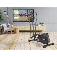
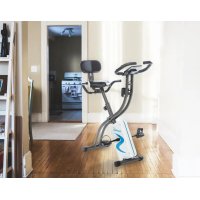
Centaurus - Exercise bike Skandika - Free user manual and instructions
Find the device manual for free Centaurus Skandika in PDF.

User questions about Centaurus Skandika
0 question about this device. Answer the ones you know or ask your own.
Ask a new question about this device
Download the instructions for your Exercise bike in PDF format for free! Find your manual Centaurus - Skandika and take your electronic device back in hand. On this page are published all the documents necessary for the use of your device. Centaurus by Skandika.
USER MANUAL Centaurus Skandika

skandika.com/service
| Recumbent ergometer | Importer / responsible in EU MAX Trader GmbH | |||||||
| Address Wilhelm-Beckmann-Str. 19, D-45307 Essen | ||||||||
| CE | Item No. SF-1052 Centaurus | |||||||
| Class HC | ||||||||
| Standard EN ISO 20957 | ||||||||
| Warning | ||||||||
| Please read the user manual carefully before use of machine | ||||||||
| Production date | ||||||||
| 2020 | 2021 | |||||||
| 2 B 4 S 6 T 8 9 | 11 | 12 | ||||||
| PO No: | ||||||||
| Max user weight 150 kg | ||||||||
21 Import safety notice
22 Parts list
23 Assembly instructions
28 Warm-up and cool-down
29 Computer operating instructions
34 Error messages
35 Built-in receiver
35 Transfer via Bluetooth
36 Exploded diagram
37 Guarantee conditions
| Recumbent ergometer | Importer / responsible in EU MAX Trader GmbH | |||||||
| Address Wilhelm-Beckmann-Str. 19, D-45307 Essen | ||||||||
| CE | Item No. SF-1052 Centaurus | |||||||
| Class HC | ||||||||
| Standard EN ISO 20957 | ||||||||
| Warning | ||||||||
| Please read the user manual carefully before use of machine | ||||||||
| Production date | ||||||||
| 2020 | 2021 | |||||||
| 2 B 4 S 6 T 8 9 | 11 | 12 | ||||||
| PO No: | ||||||||
| Max user weight 150 kg | ||||||||

skandika.com/service
Please visit the Skandika Service portal on our website for setup & help videos, FAQs and downloadable instructions. For more information about Skandika, simply visit our main page www.skandika.com

WARNING
To reduce risk of injury, read and understand this instruction manual before using the device! This machine is intended for home use only in accordance with the instructions provided in this manual. Read the instruction manual carefully before using this device and keep the instruction manual for future use.
SAFETY INSTRUCTIONS
In order to ensure the safety of the user, all the parts of the equipment should be checked regularly for damages and wear and tear.
If the equipment has to be handed over to a third party or if another person has to use it, they should be acquainted with the contents of this instruction manual.
The equipment is permitted to be used only by one person for the purpose of workout.
Before the first use and at regular intervals, it should be checked if the screws, nuts and other connections are tight.
Before the workout begins, all the objects with sharp edges around the equipment should be cleared away.
Work out with the equipment only when it functions perfectly.
Children have a natural play instinct and interest to experiment. Parents and supervisors should be aware of this so that the improper use of the equipment can be avoided. Thus, accidents can be avoided
If the children are allowed to use the equipment, their mental and physical health and history should be specifically considered. Children should be briefed to use the equipment properly and should never be allowed to work out without supervision. The equipment is not a toy.
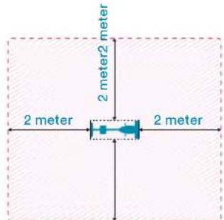
The equipment should be placed in a sufficiently large open area.
There is a possibility of damage to health due to inappropriate and excessive workout.
- Please take care that the lever and other adjusting mechanisms do not protrude in the range of motion during the workout.
The equipment should be placed on an even surface and the possible unevenness of the floor shall be compensated with appropriate measures.
- Wear suitable sportswear and sports shoes during the workout. The sportswear should not get stuck in the equipment due to its form. The shoes should have a firm grip and antiskid sole.
Before taking up a gym training program, you should consult your doctor. He can give information about the maximum recommended weight, workout duration and workout goals as well as the diet.
IMPORTANT RECOMMENDATIONS
- Setup the equipment exactly according to the assembly instructions and use only the accompanying equipmentspecific individual parts for setting up the equipment. Check the delivery for completeness with the help of the parts list of the assembly instructions.
- Place the equipment on a dry, even surface and protect it from moisture and humidity. In order to protect the floor from drag marks and stains, place a suitable antiskid mat under the equipment.
Generally it holds that the sports equipments are not a toy. Thus, they are allowed to be used in a proper manner and by appropriately informed and instructed individuals. - Abort the training immediately if you experience dizziness, nausea, chest pain or other abnormal symptoms and see your doctor immediately.
Children and handicapped people should use the equipment only in the presence of another person, who can provide appropriate guidance and assistance. - Keep yourself and others away from the moving parts of the equipment during the workout.
- Ensure correct setting of the adjustable parts and the marked maximum setting positions of the individual parts, e.g. saddle.
- Never workout directly after a meal!

| No. Name Spec. Qty | |||
| 1 Front base frame JD-9101 1 | |||
| 2 Rear foot 95.4*50.6*2.0Tx500L 1 | |||
| 3 Front foot 95.4*50.6*2.0T*450 1 | |||
| 4L Foot cap rear left (triangular) 103*68*83 1 | |||
| 4R | Foot cap rear right (tian-gular) | 103*68*83 1 | |
| 5 Supporting tube JD-9101 1 | |||
| 6 Adjustable beam 50*100*2.0T*740 L | 1 | ||
| 7 Lock washer | D15.4xD8.2x2T | 12 | |
| 8 Allen screw | M8*1.25*40 | 4 | |
| 9 Allen screw | M8*1.25*20L | 12 | |
| 10 Nylon nut | M8*1.25*8T | 9 | |
| 11 Curved flat washer | D22*D8.5*1.5T | 5 | |
| 12L Chain casing left | 1 | ||
| 12R Chain casing right | 1 | ||
| 13 Flat washer | D16xD8.5x1.2T | 28 | |
| 14 Allen screw | M8x1.25x15L | 11 | |
| 15L Pedal arm left | 6 1/2"x9/16"-20UNF 1 | ||
| 15R Pedal arm right | 6 1/2"x9/16"-20UNF 1 | ||
| 16L/R Pedal | JD-22A 9/16" | 1 | |
| 17 Allen Screw | M8*1.25*70 | 4 | |
| 18 Pedal arm shaft welding set | 1 | ||
| 19 C-Ring | S-16(1T) 2 | ||
| 20 Screw | M6x1.0x15L | 4 | |
| 21 Nylon nut | M6x1.0x6T | 4 | |
| 22 Screw | M8x1.25x25 | 2 | |
| 23 Screw cover | D23x6.5 | 2 | |
| 24 Bottom bracket | #6003ZZ | 2 | |
| 25 Belt (with running grooves) 420 PJ6 1 | |||
| 26 Magnet system | D274x122L | 1 | |
| 27 Flat washer | D22*D10*2T | 2 | |
| 28 Safety screw | 3/8"-26UNFx6.5T | 2 | |
| 29 Flat washer | D25*D8.5*2.0T | 1 | |
| 30 End cap | D25.4x31L | 2 | |
| 31 Mounting panel | 1 | ||
| 32 Spring | D3*D17*65L | 1 | |
| 33 Clamping bracket | D23.8xD38x24 | 1 | |
| 34 Nylon nut | M10x1.5x10T | 2 | |
| 35 Spacer plate | D22.5*D17.2*6.4T | 1 | |
| 36 Nylon nut | M8*1.25*8T | 1 | |
| 37L Chain casing left | 1 | ||
| 37R Chain casing right | with power hole | 1 | |
| 38 Back rest 422*404.6*57.2 | 1 | ||
| 39 Motor | 1 | ||
| 40 Linkage | D1.5x400 | 1 | |
| 41 Adjustable pipe | D12*122*162 | 1 | |
| 42 Seat | 348*270*52 | 1 | |
| 43 Foot cover cap (Transfer) | 123*70*110 | 1 | |
| 44 Foot cover cap (adjustable) | 123*70*110 | 1 | |
| 45 Cover cap rectangular | 25*25*13L | 4 | |
| 46 Upper pulse cable | 750L | 2 | |
| 47 Lower pulse cable | 1820L | 1 | |
| 48L Left handle of the welding set | 1 | ||
| 48R Right handle of thewelding set | 1 | ||
| 49 Buffer | D20*10L*M8*1.25 | 2 | |
| 50 Central pulse cable | 900L | 1 | |
| 51 Spacer | 125*75*53 2 | ||
| 52A Upper computer cable | 750L | 1 | |
| 52B Lower computer cable | 600L | 1 | |
| 53 Sensor cable | 1 | ||
| Phillips screw M5x0.8x12L | 1 | ||
| 54 Pulse cable | 800L | 1 | |
| 55 Pulley | D255x17 | 1 | |
| No. Name Spec. Qty | |||
| 56 Grip | 2 | ||
| 57 | Flat washer | D22xD17x0.3T | 2 |
| 58 Screw | M8*1.25*25L | 1 | |
| 59 Round magnet M51 1 | |||
| 60 | Computer | SM2560-31 | 1 |
| 61 | Flat washer | D24xD16x1.5T | 2 |
| 62 Casing | D23*4T*540L | 2 | |
| 63 | End piece | D25.4x28L | 2 |
| 64 | Upper protective casing | 1 | |
| 65 | Screw | ST4*1.41*15L | 8 |
| 66 | Phillips screw | M5*10L | 4 |
| 67 Phillips screw M5x0.8x10L | 3 | ||
| 68 | Backrest support | 1 | |
| 69 | Rectangular covering cap | 30x60x15 | 2 |
| 70L | Mounting plate left | 159.4*71*5T | 1 |
| 70R | Mounting plate right | 159.4*71*5T | 1 |
| 71 | Rear decorative cover | D91*220L | 1 |
| 72 | Front decorative cover | D91*220L | 1 |
| 73 | Round Phillips screw | ST4x20L | 4 |
| 74 | Round covering cap | D1**17 | 2 |
| 75 | Knob | D61*46 | 1 |
| 76 | C Ring | S-12(1T) | 3 |
| 77 Spacer plate | D19xD13.1x4T | 1 | |
| 78 | Shaft | D15.9*D13*219L | 1 |
| 79 Flat washer | D24*D13.5*2.5T | 1 | |
| 80 | Spacer | D29*D12.1*9T | 2 |
| 81 | Buffer | 40.5*28.5*6T | 1 |
| 82 Stopper tube | 53*41*38 | 1 | |
| 83 Small protective covering | 95.4*69*49.3 | 1 | |
| 84 | Round end cap | 6/8"×17 5 | |
| 85 Casing | D10*245L*3T,HDR | 1 | |
| 86 Adjustable wheel | D59*M10*40L | 2 | |
| 87 | Casing | D23*4T*150L | 2 |
| 88 Seat rod | 1 | ||
| 89 | Plastic casing | D3*30L | 2 |
| 90 | Computer mounting bracket | 1 | |
| 91 | Oval end cap | 40*80*63.5 | 1 |
| 92 Flat washer | D50*D10*1.0T | 3 | |
| 93 Shaft casing | D60*13.5L | 2 | |
| 94 | Cap | D29.1*13L | 2 |
| 95 Fixing clamp | 1 | ||
| 96 | Screw | M8*1.25*60L | 1 |
| 97 | C Ring | S-17(1T) | 1 |
| 98 | Flat washer | D23*D17.2*1.5T | 1 |
| 99 | Decorative cover for the backrest | 1 | |
| 100 | Phillips screw | M6*1.0*25L | 4 |
| 101 | Pin | D6*26.5*7.7 | 2 |
| 102 | Phillips screw ST4.2x1.4x20L | 19 | |
| 103 | Phillips screw | ST4.2*20L | 4 |
| 104 | Adapter | 1 | |
| 105 | Power cable | 900L | 1 |
| 106 | Phillips screw | ST4.2*1.4*15L 4 | |
| 107 | Water bottle holder | 120*87*3T | 1 |
| 108 | Water bottle | 1 | |
| 109 | Phillips screw | M5*0.8*15L | 2 |
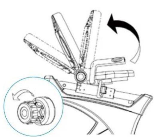
ASSEMBLY INSTRUCTIONS
1
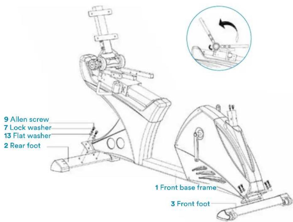
Fix the front 3 and rear foot 2 to the base frame with the help of the Phillips screw 9, lock washer 7 and the flat washer 13. Adjust the stability by rotating the small wheels in the casing cap of the rear base.
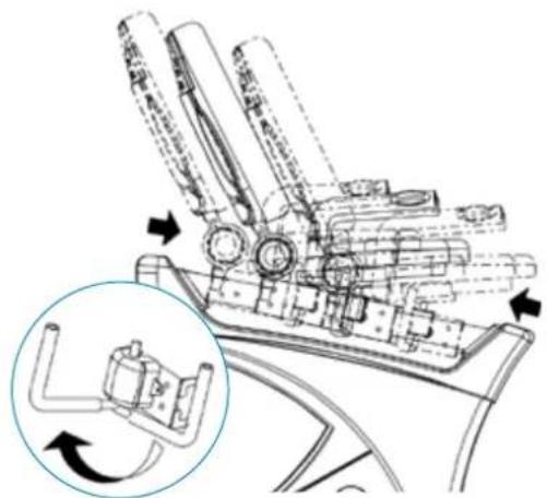
2
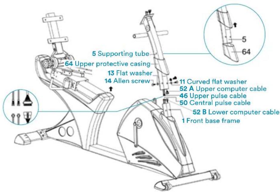
Push the upper protective covering 64 on the support tube 5. Connect with 2 sets of cable: with upper and lower computer cable 52A & 52B, and with the upper and middle pulse cable 46 & 50. Push the upper protective casing 64 upwards and connect the support tube 5 with the base frame 1 with the help of the Phillips screw 14, the flat washer 13 and the curved flat washer 11.
3
Connect the upper pulse cable 46 and the upper computer cable 52A with the computer 60. Mount the computer with the screw 66. Assemble the left and right pedal 16L &16R with the left and right pedal arms 15L & 15R.
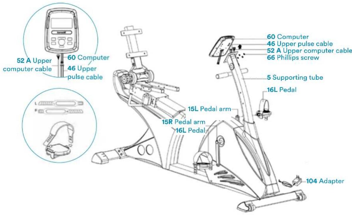
4
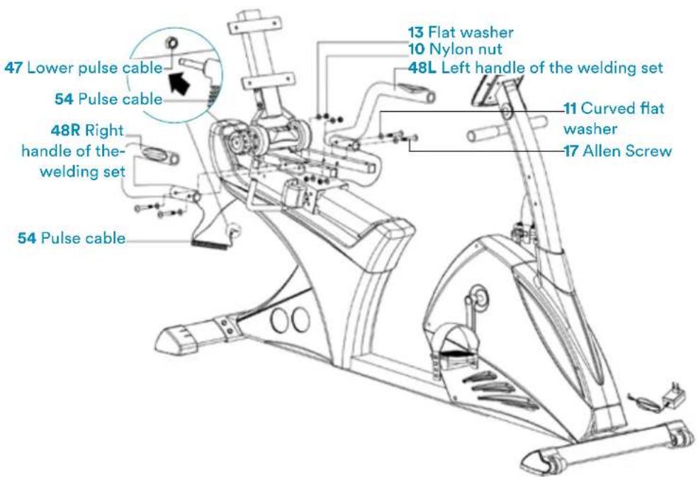
Connect the left and right grip 48L & 48R to the main frame 1 with the help of the Phillips screw 17, the curved flat washer 11, the flat washer 13 and the nylon nut 10. Connect the pulse cable 54 with the lower pulse cable 47.
5
Connect the seat 42 with the support tube with the help of the Phillips screw 8 and the flat washer 13. Connect the backrest to the backrest support 68 with the help of the Phillips screw 9 and the flat washer 13.

6
Connect the decorative cover for the backrest 99 to the backrest 38 with the help of the Phillips screw 100. Fix the round end cap 84. Fix the bottle holder 107 with the help of the screw 109 and place the water bottle 108 in the holder. Connect the adapter 104.
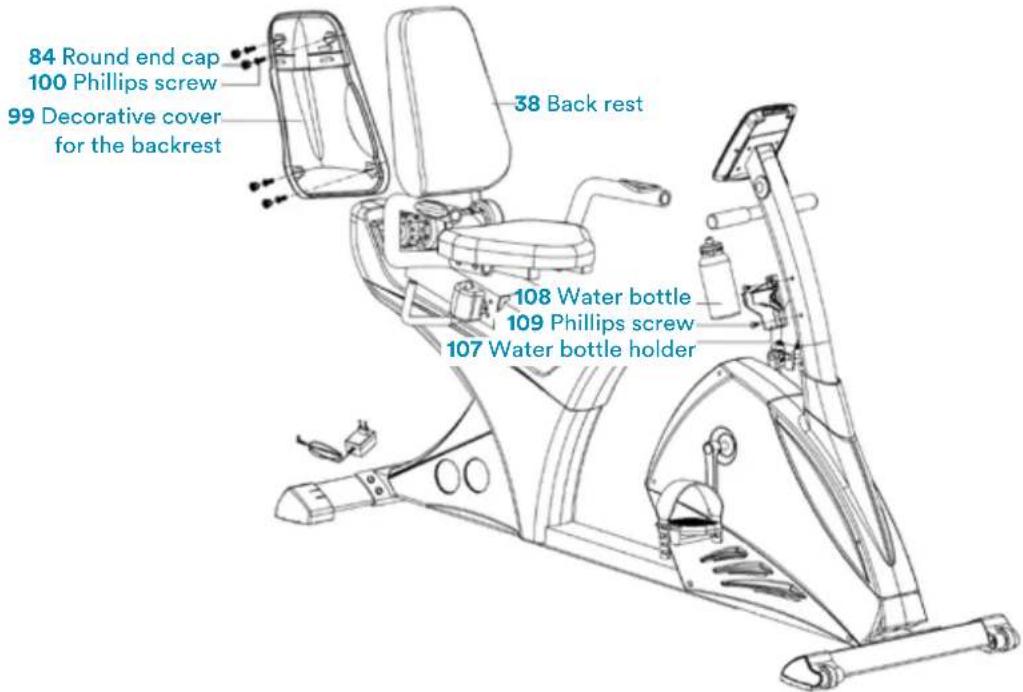
Adjust the seat forwards or backwards. Adjust the backrest with the knob 75.
7

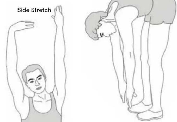
Toe Touch
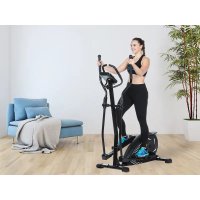
A successful exercise program consists of a warm-up, aerobic exercise and a cool-down. Exercise for at least two or preferably three times a week, resting for a day between workouts. After several months, you may increase the frequency to four or five times per week.
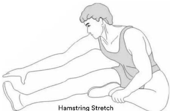
WARM-UP
This stage helps to improve the blood circulation and prepares the muscles for your workout. It additionally helps to reduce the risk of injury or cramps. It is recommended to do some stretching exercises as shown here below. Hold each stretching position for approximately 30 seconds.
Never force or jerk yourself into a stretching position - if you feel pain, STOP immediately. Warm-up exercises may also include brisk walking, jogging, jumping jacks, jump rope exercises or running in place.
STRETCHING
Muscles can be stretched more easily when these are warm. This reduces the risk of injury. Do not bounce.

Calf-Achilles Stretch
Inner Thigh Stretch
Remember always to check with your physician before starting any exercise program.
COOL-DOWN
This stage helps to soothe your muscles and your cardiovascular system after your workout. At the end of your workout, reduce the speed and exercise for approximately 5 minutes at this lower speed level. Afterwards, repeat the warm-up exercises as described above.
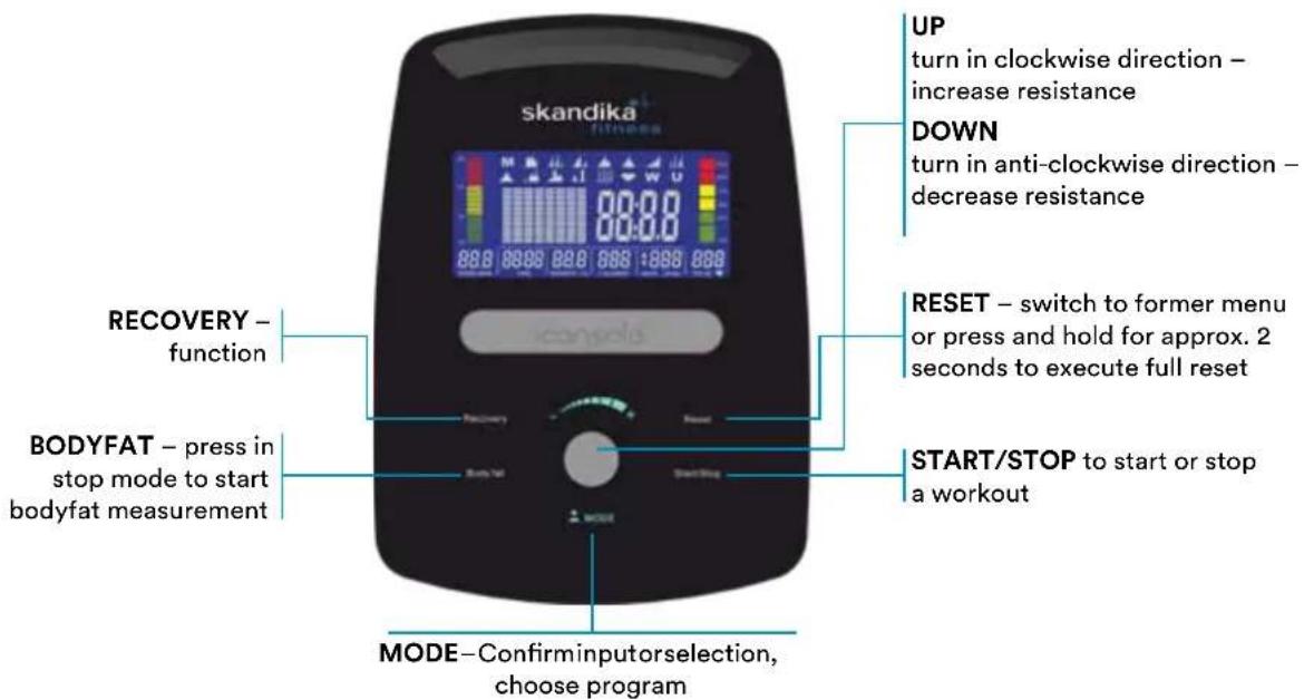
FUNKTIONEN
SPEED/RPM Speed up to max. 99.9km / h or rounds per minute up to max. 999
TIME Exercise or preset time (0:00 up to max. 99:59 min.)
DISTANCE Distance up to max. 99.9 km
CALORIES Approximate calorie consumption (0 to 999 kcal)
PROGRAM Program modes (12 programs are available)
USER User-defined program PROGRAM
H.R.C. Heartrate-controlled training mode
WATT Watt-controlled training mode PROGRAM
POWER ON
Plug in power supply. Computer will power on and full display will be shown for approx. 2 seconds (figure 1).
In the next step you can enter user data by selecting a user from U1 to U4 with UP/DOWN and confirm with MODE. Set sex, age, height and weight (figure 2). After setting all user data, computer will switch to main menu (figure 3).
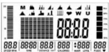
Fig.1
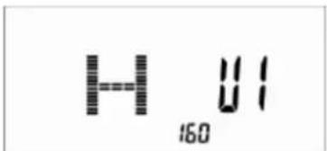
Fig. 2
Fig. 3
WORKOUT SELECTION
Select the workout mode with UP, DOWN and MODE to confirm:
M (manuel) ->
P (program 1-12) ->
H.R.C ->
W (WATTS) ->
U (user).
MANUAL MODE
In manual mode you can adjust the load manually. After selecting M (confirm with MODE-button) you can select the initial tension level (use UP, DOWN and MODE to select, figure 4). Press START/STOP. You may change the tension level at any time during exercise with UP and DOWN. You may also input target values for the following function values
a. TIME (figure 5)
b. DISTANCE (figure 6)
c.CALORIES (figure 7)
d. PULSE (figure 8)
To input a target value, do not press Start/Stop after selecting the initial tension level, but instead use UP, DOWN and MODE to input the target values. After your input, press START/STOP to start the workout. To pause your workout, press the START/STOP-button again. Press RESET to return to main menu.
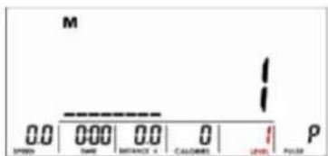
Fig. 4 Fig. 5
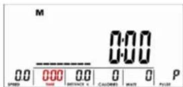
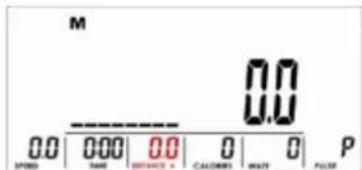
Fig. 6 Fig. 7
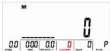
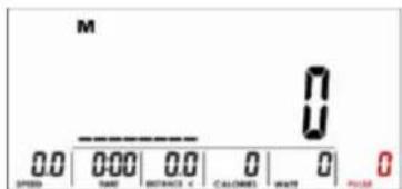
Fig. 8
Fig. 9
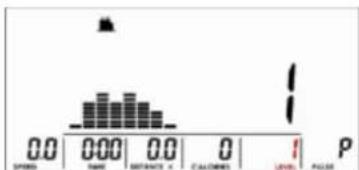
Fig. 10
PROGRAM MODE
Within this mode you can exercise with a program profile (preset). Mountain- and valley courses: After selecting program mode and MODE按钮 for confirmation, P1 appears on the display. Choose one of the 12 programs (P1 to P12). Select the initial
tension level (use UP, DOWN and MODE to select, figure 10). You may now preset a target value for TIME by using UP, DOWN and MODE. Press START/STOP to start workout. You may change the tension level at any time during exercise with UP and DOWN. To pause your workout, press the START/STOP-button again. Press RESET to return to main menu.
H.R.C MODE
After selecting this mode (press MODE to confirm) you are in the heart frequency controlled mode. You can run an automatically steered training depending on your pulse frequency. Press UP or DOWN to select one of the following alternatives:
$$ \begin{array}{l} \begin{aligned} & \text{(figure 11)} = 55\% \text{Max H.R.C.} -\text{Target H.R} = \ & (220 - \text{AGE})\times 55\% \end{aligned} \ \begin{aligned} & \text{(figure 12)} = 75\% \text{Max H.R.C.} -\text{Target H.R} = \ & (220 - \text{AGE})\times 75\% \end{aligned} \ \begin{aligned} & \text{(figure 13)} = 90\% \text{Max H.R.C.} -\text{Target H.R} = \ & (220 - \text{AGE})\times 90\% \end{aligned} \ \text {(f i g u r e 1 4)} = \text {T A G} = \text {T a r g e t H . R . C . -} \ \end{array} $$
In TAG mode, use UP/DOWN Buttons for direct input of the target pulse value (between 30 and 230 bpm). You may now preset a target value for TIME by using UP, DOWN and MODE. Press START/STOP to start workout. To pause your workout, press the START/STOP button again. Press RESET to return to main menu.
WORKOUT SELECTION
Select the workout mode with UP, DOWN and MODE to confirm:
$$ \begin{array}{l} M (\text {m a n u e l}) \rightarrow \ P (\text {p r o g r a m} 1 - 1 2) \rightarrow \ \mathbf {H}. \mathbf {R}. \mathbf {C} \rightarrow \ \mathrm {W} (\text {W A T T S}) \rightarrow \ U (\text {u s e r}). \ \end{array} $$
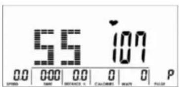
Fig.11 Fig.13
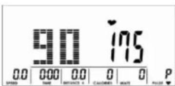
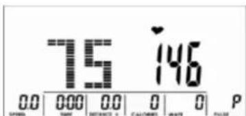
Fig. 12
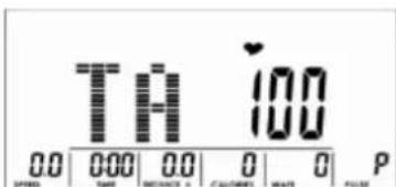
Fig. 14
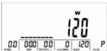
Fig. 15
WATT MODE
With this mode you can exercise according to the preset Watt value. After selecting W, press MODE to enter this mode. The default value for the WATT preset value is 120 (figure 15), which you may change with UP/
DOWN and MODE. You may now preset a target value for TIME by using UP, DOWN and MODE. Press START/STOP to start workout. The computer will automatically control the resistance. You may change the watt level at any time during exercise with UP and DOWN. To pause your workout, press the START/STOP-button again. Press RESET to return to main menu.
WORKOUT SELECTION
Select the workout mode with UP, DOWN and MODE to
confirm:
M (manuel) ->
P (program 1-12) ->
H.R.C->
W (WATTS) ->
U (user).
Fig. 16
USER PROGRAM MODE
After selecting this mode (U and MODE for confirmation), use the UP and DOWN buttons to create your own user profile (figure 16). You can preset a different resistance level for totally 8 columns. Press MODE
to continue or hold MODE button for at least 2 seconds to quit the setting process. You may now preset a target value for TIME by using UP, DOWN and MODE. Press START/STOP to start workout. You may change the tension level at any time during exercise with UP and DOWN. To pause your workout, press the START/STOP-button again. Press RESET to return to main menu.
RECOVERY
With this special function, you can check your hearts recovery rate after a training session. This is a very important indication for the physical condition of your body. Try to improve your recovery rate with regular training sessions. The aim is, to calm down to a normal pulse frequency (frequency, when you are not in motion) as quickly as possible. To check your recovery rate, you need to keep your hands onto the hand pulse-sensors (or keep wearing a chest belt) after your exercise. Now press the button RECOVERY. The computer will start to countdown 60 seconds (figure 17). During this period the computer will constantly measure your heart rate through the hand sensors. After this minute, your recovery rate will be displayed on the display. The range is F1.0 to F6.0 (figure 18), whereby F1.0 is very good and F6.0 is insufficient. Improve your value by intense and regular training! After the recovery function is finished, press RECOVERY again to return to normal operation mode.

Fig. 17 Fig. 18
BODY FAT
Press this button to start the body fat measurement.
Ux (figure 19) will be displayed. Hold both hands on the handsensors during measurement. Upon pulse is detected the display shows the symbols according to figure 20 to 22. It will last about 8 seconds until the measurement is finished. After the measurement, the BMI (figure 23), the fat % (figure 24) and fat advice symbol (figure 25) will be displayed.


Fig. 19 Fig. 20


Fig. 21 Fig. 22


Fig. 23 Fig. 24

Fig. 25
ERROR MESSAGES
“ 1
means, that the contact to the handpulse sensors was not sufficiently for a measurement. The reason for this can be that you have not grasped the two sensors correctly. Start a new measurement with correctly placed hands!
E-1
means, that no heart rate signal has been detected.
E-4
appears, if the fat % or BMI values are too low (<5) or too high (>50).
NOTES
1) This computer has an automatic on/off function so that it switches on when the pedals move or when any button is pressed, and turns into stand-by mode automatically if no signal has been received for approx. 4 minutes.
2) In case of any abnormal functions, disconnect the device from power source and reconnect after some minutes
BUILT-IN RECEIVER
The computer is equipped with a built-in receiver, which can receive the pulse signals measured by a compatible (uncoded/5 kHz, e.g. Skandika chest belt) chest belt wirelessly.
So you can decide, if you want to measure your pulse frequency by the hand sensors or by the chest belt. A chest belt would enable you to exercise without the need to grasp the hand sensors all the time. Make sure, the correct battery is inserted into the chest belt if you want to use this feature.
You may adjust the strap to a comfortable length. However, the electrodes must have contact with your skin in order to measure your heart rate correctly. It may last up to one minute before a correct display can be seen.
Always pay attention to the instruction manual of the chest belt device. In case you grip the hand sensors and wear a chest belt at the same time, the device will prefer the signal from the hand sensors.
The computer can be connected via Bluetooth (frequency: 2.4 GHz) to communicate with the apps iConsole+ or KinoMap.
ICONSOLE+
Activate Bluetooth on your mobile device, download the app „iConsole+“ an install on your iOS- or Android device. You may use the app search function of your mobile device or the following QR code to find the app:

iConsole Global

System requirements:
Android 5.0 or newer with Bluetooth 4.0 iOS 10 or newer with Bluetooth 4.0
BFor Android devices, „unknown sources“ need to be accepted in the device security settings („Settings -> Device security“).
After starting the app, the connection with the training device need to be established via Bluetooth - therefore select „Quick Start“, „Interval“, „Map“:


Once console is connected to smart device via Bluetooth , the console will power off.
In case of mechanical problems use this explosion drawing. All parts are marked with a specific part number in it. Tell us this number in order to replace the respective part (within warranty time this service may be free of charge). If necessary, you may additionally use the free user manual in pdf-format, available on www.skandika.com. You may enlarge the explosion drawing there with a factor up to 500% .
GUARANTEE CONDITIONS
For our devices we provide a warranty as defined below.
- In accordance with the following conditions (numbers 2-5) we repair defect or damage to the device free of charge, if the cause is a manufacturing defect. Therefore, these defects / damages need to be reported to us without delay after appearance and within the warranty period of 24 months after delivery to the end user. The warranty does not cover parts, which easily break (e.g. glass or plastic). The warranty does not cover slight deviations of the product, which are insignificant for usability and value of the device and damage caused by chemical or electrochemical effects and damages caused by penetration of water or generally force majeure damage.
- The warranty achievement is the replacement or repair of defective parts, depending on our decision. The cost of material and labor will be borne by us. Repairs at customer site cannot be demanded. The proof of purchase along with the date of purchase and / or delivery is required. Replaced parts become our property.
- The warranty is void if repairs or adjustments are made,
which are not authorized by us or if our devices are equipped with additional parts or accessories that are not adapted to our devices. Furthermore, the warranty is void if the device is damaged or destroyed by force majeure or due to environmental influences and in case of improper handling / maintenance (e.g. due to non-observation of the instruction manual) or mechanical damages. The customer service may authorize you to replace or repair defective parts after telephone consultation. In this case, the warranty is not void.
- Warranty services do not extend the warranty period nor do they initiate a new warranty period.
- Further demands, especially claims for damages which occurred outside the device, are excluded as long as a liability is not obligatory legal.
- Our warranty terms - which cover the requirements and scope of our warranty conditions - do not affect the contractual warranty obligations of the seller.
- Parts of wear and tear are not included in the warranty.
- The warranty is void if not used properly or if used in gyms, rehabilitation centers and hotels. Even if most of our units are suitable for a professional use, this requires a separate agreement.

ENVIRONMENTAL PROTECTION
At the end of its life cycle, this product must not be disposed of with household waste but must be taken to a collection unit for the recycling of electric and electronic equipment. The symbol on the product, the instructions for use or the packaging express mention of this. The basic materials can be recycled as specified on the labelling.
When recycling the materials and finding other utilisation for used equipment, you are making a significant contribution towards protecting our environment. Ask at your council about the respective local disposal sites.
In accordance with our policy of continual product improvement, we reserve the right to make technical and visual changes without notice.
For spare parts please contact: service@skandika.de
Service centre: MAX Trader GmbH, Wilhelm-Beckmann-Straße 19, 45307 Essen, Germany
Contenu
| Recumbent ergometer | Importer / responsible in EU MAX Trader GmbH | |||||||
| Address Wilhelm-Beckmann-Str. 19, D-45307 Essen | ||||||||
| CE | Item No. SF-1052 Centaurus | |||||||
| Class HC | ||||||||
| Standard EN ISO 20957 | ||||||||
| Warning | ||||||||
| Please read the user manual carefully before use of machine | ||||||||
| Production date | ||||||||
| 2020 | 2021 | |||||||
| 2 B 4 S 6 T 8 9 | 11 | 12 | ||||||
| PO No: | ||||||||
| Max user weight 150 kg | ||||||||

skandika.com/service
P (programme 1-12) ->
H.R.C->
W (WATT) ->
P (programme 1-12) ->
H.R.C->
W (WATT) ->
P (programme 1-12) ->
H.R.C->
W (WATT) ->