TEC 350 - DJ Equipment Skytec - Free user manual and instructions
Find the device manual for free TEC 350 Skytec in PDF.
User questions about TEC 350 Skytec
0 question about this device. Answer the ones you know or ask your own.
Ask a new question about this device
Download the instructions for your DJ Equipment in PDF format for free! Find your manual TEC 350 - Skytec and take your electronic device back in hand. On this page are published all the documents necessary for the use of your device. TEC 350 by Skytec.
USER MANUAL TEC 350 Skytec
Congratulations on the purchase of this SkyTec mixer. Please read this manual carefully prior to using the unit.
Warning:
- Read the manual prior to using the unit.
- Keep the manual for future reference.
- Keep the packaging for safer transport in its original packaging
- For indoor use only.
- Prior to the first use, have the unit checked by a qualified person.
- The unit contains voltage carrying parts. DO NOT open the mixer.
- When you unplug the unit from the mains always pull the plug, never the lead.
- Never plug or unplug the unit with wet hands.
If the plug and/or mains lead are damaged, they need to be repaired by a qualified technician. - If the unit is damaged to an extent that you can see internal parts, do not plug the unit into a mains outlet.
- Repairs and lamp replacement has to be carried out by a qualified technician.
- Only connect this unit to an earthed mains outlet of 230Vac / 50Hz and 10-16A.
- Do no place the unit near heat sources.
- Always unplug the unit during a thunderstorm or when it is not in use.
- If the unit has not been used for a longer period of time, condensation can occur inside the housing. Please let the unit reach room temperature prior to use.
- Keep out of the reach of children.
- All channel controls and the master volume control must be set to zero prior to switching the unit on.
- To prevent clipping of the amplifier do not set the volume level too high.
- Switch the amplifier on at latest and switch it off at first.
- Do not use cleaning sprays for the slider controls. The residues of these spray cause dust deposits in the controls. If a problem occurs, please consult a specialist.
General description
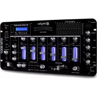
The professional stereo mixer TEC 350 features 5 separate input channels of which 2 are convenient for microphones. A slider control with a LED vu-meter on the MASTER output ensures an accurate setting of the signal level to the amplifier. The built-in stereo headphone amplifier with volume control can be set to any input channel and to the MASTER output. The unit is convenient for rack mounting or free-standing. For indoor use only. Do not attempt to repair the unit yourself. Repairs should only be carried out by a qualified technician. The only user serviceable part is the crossfader. The unit is powered from 230Vac and MUST BE EARTHED.
Connections and Controls
MIC channel
The input of the mono microphone channel is via an XLR/jack connector (6) on the top left side of the panel. See diagram below for the different possible connections. The MIC slider control (7) sets the level of the microphone signal. The TALKOVER switch (8) reduces the sound level of the channels A to D to ensure that the microphone signal is audible over the music.
Channels 1 to 3
These three stereo channels are identical. Every input accepts a CD player or a turntable via RCA phono sockets (21) on the rear panel. The channels feature a 2-band tone control (3&4) and a selector switch for turntable or CD player operation (2).
Channel 4
This channel has a stereo line input (19) (CD, cassette deck or another mixer) and a 6.3mm mono input for an extra microphone (20).
Crossfader
This slider controls allows to fade between two of the channels A to D. Example: Set the left ASSIGN knob (11) to A and the right ASSIGN knob to D. If you push the crossfader (12) completely to the left, you will only hear the sound of channel A. If you push it completely to the right, only channel D will be heard. You can set any combination of the two ASSIGN knobs. The slider controls of the two selected channels must of course be pushed upwards.
Master section
The MASTER slider control (10) sets the total output level to the amplifier. The level is indicated on the LED vu-meter (9). Set the level to a point where the red LEDs only light up very shortly in order to avoid overdrive. The RCA phono output to be connected to the amplifier is on the rear panel and marked MASTER (18). The adjacent socket marked 'REC' (17) is for connection of the output signal to a cassette recorder.
Headphone section
Connect a stereoophone via a 6.3mm jack plug (15). Select one of the 5 input channels or the MASTER output channel via the rotary knob (13). Set the volume via the LEVEL knob (14).
Power ON
After having connected the audio sources to the mixer and the mixer to the amplifier, set all slider controls to the lowest position. Only then switch on the mixer and the amplifier.
Replacement of the crossfader
Due to the intensive use of this control, it needs replacement after some time. This is very easy and requires no soldering. Remove the two screws on the panel of the crossfader via a crosshead screwdriver. Lift off the control from the mixer and disconnect it. Push the connector on the new crossfader (this can only be done one way). Insert the crossfader panel back into the mixer and fasten the two screws.
Different ways of connecting the combined microphone input
If you want to use the XLR input unbalanced, connect the centre pin to the ground
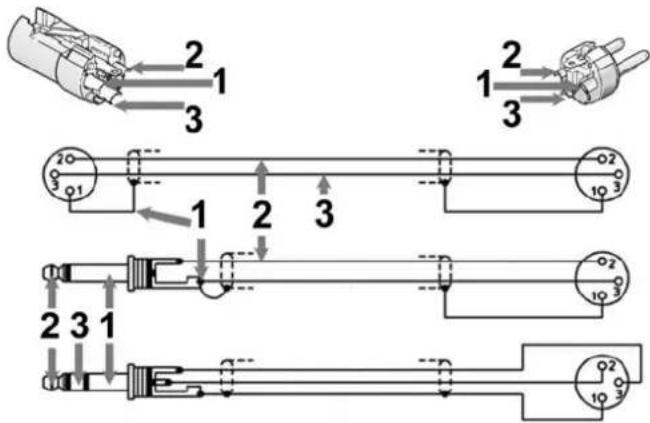
1 = Ground
$$ 2 = + (L i v e) $$
$$ 3 = - (\text {R e t u r n}) $$
FUNCTIONS
Front Panel
- POWER On/Off switch
- INPUT SELECTOR (4x) Selects the input signal for both channels
- TREBLE (4x) Treble control for both channels
- BASS (4x) Bass control for both channels
5.CHANNEL (4x) Slider controls for the volume of both channels - MICROPHONE 6.3mm/XLR combi jack for a microphone
- MIC LEVEL Setting of the microphone output level
- TALKOVER Switch that attenuates the sound of every channel when t mic is used
- VU-METER Displays the strength of the output signal
- MASTER Master control for the volume of the output signal
- ASSIGN Channel selection knob for the crossfader function
- CROSSFADER Fast fading between the channels
- CUE SELECT Selects the channel to be heard through the headphones
- PFL LEVEL Sets the volume to the microphone output
- HEADPHONE 6.3mm Jack socket for the headphones
Rear Panel
- EARTH Earth connector for the ground wire from the turntables
- REC RCA sockets for connection to a recorder
- MASTER RCA sockets to the amplifier
19/21 CHANNEL PHONO & LINE RCA sockets for connection to a PHONO or LINE (CD player, tuned, etc.) for the different - MIC 6.3mm Jack connector for the microphone
Do not attempt to make any repairs yourself. This would invalid your warranty.
Do not make any changes to the unit. This would also invalid your warranty.
The warranty is not applicable in case of accidents or damages caused by inappropriate use or disrespect of the warnings contained in this manual.
SkyTronic UK cannot be held responsible for personal injuries caused by a disrespect of the safety recommendations and warnings. This is also applicable to all damages in whatever form.